Advertisement
Quick Links
Advertisement

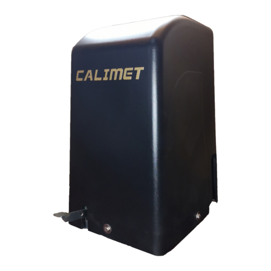
Summary of Contents for Calimet CM-5-ACFP
- Page 2 PRODUCT SPECS : Voltage Input:110V Maximum output current:15AM,Fuse: AC110V 15AM Remote control distance: Open space >150 Feet (50 meters) WARNING To reduce the risk of INJURY or DEATH: Never let children operate or play with gate control, keep remote control away from children.
-
Page 3: Installation Of Base
Installation of Base Lay out position of 6 Anchors by measuring clearance between anchors and inside edge of gate. Figure 1 Install underground conduits in area for conduits. Figure 2 Figure 1 Figure 2... - Page 4 Installation Barrier distance Figure 3 Figure 4...
- Page 5 Position of gate and operator Two options of chain connection. Figure 5 Front Mount Figure6 Rear Mount...
- Page 6 Welding Bracket of Chain Figure 7 Correct connection of chain Figure 8 Figure 8. Follow the correct way to install chain. Incorrect installation will cause malfunction of operator and potential damages.
-
Page 7: Power Connection
Power Connection Figure9 1. MUST us UL proved power wires, power wires MUST have minimum capacity for 25 Am current. 2. All operators MUST properly grounded in order to prevent electrical charge. Must use dedicated circuit for power supply. 3. When power connected, turn power switch in operator to ON position. - Page 8 EMERGENCY RELEASE Figure 10 A. Emergency Release of gate Disconnect power. Push Release pedal downward and move slightly to the right until it was locked in down Position. Hold and push gate to desired direction. Reset pedal (Only when operator has No reaction while using remote control) Push pedal downward from locked position and slightly move to the left, unlocked Pedal.
- Page 9 Entrapment protection Safety and Exit loop Figure 11...
-
Page 10: Control Board Layout
Control Board lay out Figure 12... - Page 11 Gate Travel Limit Adjustment Figure 13 Turn up or down of both wheels to adjust distance between them, making gate stop at the position desired.
- Page 12 Use Remote Control Device Figure 12 There are two modes to set Remote Control: Self-study Mode& Numeric Mode Self-study code may be set up to 60 groups. Self-study mode corresponds to receiver in control board. Press and hold STUDY key for 3 seconds until flashing light turn to solid bright, press any key on Remote Control until STUDY light turn to flashing again, setting done.
- Page 13 Use DIP Switches Figure 15 DIP switch TIMER: 1-60S Timer: Auto activated to close gate upon set time ( 1~ 60 seconds). RADIO: Remote control radio receiver, allow remote control to close gate without timer activation. OSC: Remote control priority. Allow remote control to direct gate movement whenever gate is moving in any direction.
- Page 14 Use Infrared Control Figure 16 Follow infrared control instruction to connect power. Common wire connected to Common pole, Signal wire connected to OPEN or CLOSE pole. Use of External Receiver Figure 17 Ports on external receiver are marked as 1, 2, and 3. NO: 1 is COMMON pole, NO: 2 is RELAY pole, NO: 3 is 24 VDC...
- Page 15 Slave operator activation Figure18 1. Set SLAVE switch on SLAVE CONTROL BOARD to ON position. 2. Use UL proved electric wire connect DATA- and DATA- from Master control board to Slave control Board, then connect DATA+ and DATA+ accordingly. 3. M/LINK light turn to solid bright. Use Reversing Device Figure 19 1.
- Page 16 Remote Control & Timer Delay Closing Figure 20 Remote Control delay closing Choose time delay to activate operator between 0~6 seconds by turning knob on DELAY Timer automatic delay closing On DIP switch Set key TIMER to ON position (Figure 15 ) Adjust knob on TIMER between 0~60 seconds to activate operator.


Need help?
Do you have a question about the CM-5-ACFP and is the answer not in the manual?
Questions and answers