Table of Contents
Advertisement
Quick Links
Advertisement
Table of Contents

Summary of Contents for Snom M500
- Page 1 M500 Multi-cell SIP DECT Base Station Quick Installation Guide...
-
Page 2: Important Safety Information
Important Safety Information This symbol is to alert you to important operating or servicing instructions that may appear on the product or in this user’s manual. Always follow basic safety precautions when using this product to reduce the risk of injury, fire, or electric shock. - Page 3 12. To reduce the risk of electric shock, do not disassemble this product, but take it to an authorized service facility. Opening or removing parts of the base station or handset other than specified access doors may expose you to dangerous voltages or other risks.
- Page 4 19. Use only the power cord indicated in this manual. 20. For pluggable equipment, the socket-outlet shall be installed near the equipment and shall be easily accessible. 21. In wall mounting position, make sure to mount the telephone base on the wall by aligning the eyelets with the mounting studs of the wall plate.
- Page 5 14. Débranchez cet appareil de la prise de courant et communiquez avec le département de service à la clientèle de Snom dans les cas suivants: A. Lorsque le cordon d’alimentation est endommagé ou écorché.
- Page 6 15. Évitez d’utiliser un téléphone (autre qu’un sans fil) pendant un orage. Les éclairs peuvent être à l’origine d’une électrocution. 16. N’utilisez pas le téléphone pour rapporter une fuite de gaz à proximité de celle-ci. Sous certaines circonstances, une inteincelle pourrait survenir lorsque l’adaptateur est branché...
- Page 7 Compliance FCC part 15 This device complies with Part 15 of the FCC rules. Operation is subject to the following two conditions: (1) This device may not cause harmful interference, and (2) this device must accept any interference received, including interference that may cause undesired operation.
- Page 8 Compliance Industry Canada This Class A digital apparatus complies with Canadian requirements: CAN ICES-3 (A)/NMB-3(A). Cet appareil numérique de la classe A est conforme à la norme CAN ICES-3 (A)/NMB-3(A) du Canada. This device contains licence-exempt transmitter(s)/receiver(s) that comply with Innovation, Science and Economic Development Canada’s licence-exempt RSS(s).
-
Page 9: About This Guide
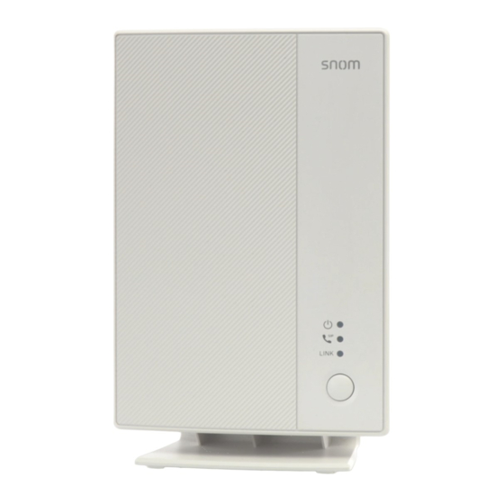
For customer service or product information, visit our website at www.snomamericas.com Parts Checklist Your package contains the following items. Save your sales receipt and original packaging in the event warranty service is necessary. Ethernet cable Quick start guide M500 Quick Installation Guide Base Station... - Page 10 Quick Reference Guide Base station external features - Front view Power LED SIP LED LINK LED LINK button...
- Page 11 Base station external features - Rear view Holes for wall mounting USB port Network and PoE port Reset button Press for 15 seconds to restore factory defaults AC adapter input If no POE available Multicell port for connecting another M500...
- Page 12 Status Indicators on the Base Station Power LED SIP LED LINK LED Color Pattern Description Power Green Steady • Base station just powered ON and proceeding to IP retrieval • Power has been On and IP is assigned to desksets/handsets •...
- Page 13 Quick • Ready to deregister deskset/handset Flash Steady • This base station is registered and connected with other base stations, but the M500 system has no record of deskset/handset Slow • This base station cannot connected with other registered Flash...
-
Page 14: Base Station Installation
Base Station Installation This section assumes that your network infrastructure is established and that your IP PBX phone service has been ordered and configured for your location. You can power the base station using Power over Ethernet (PoE) from your network or using a power adapter (sold separately). - Page 15 “5V DC” and hook up the plug to the wall outlet. The second RJ45 connector, labeled “MULTI-CELL”, is for daisy-chaining further M500 base stations without the need for a second Ethernet connection line. Up to six M500 base stations can be connected for single cell or multi-cell operation.
- Page 16 Mounting the base station on a wall Unscrew the foot stand, and remove it from the base station. 2. Install two mounting screws on the wall. Choose screws with heads larger than 5 mm (3/16 inch) in diameter (1 cm / 3/8 inch diameter maximum). The screw centers should be 60 cm (2 3/8 inches) apart vertically or horizontally.Tighten screws until only 3 mm (1/8 inch) of the screws are exposed.
-
Page 17: Maintenance
Maintenance Taking care of your product • Your base station contains sophisticated electronic parts, so you must treat it with care. • Avoid rough treatment. • Save the original packing materials to protect your product if you ever need to ship it. -
Page 18: Technical Specifications
Technical Specifications RF frequency band 1921.536–1928.448 MHz Channels Operating temperature 32–104 °F (0–40 °C) Power requirements Power over Ethernet (PoE): IEEE 802.3af supported, class 3 If PoE not available, power adapter (sold separately): NBS12E050200UV Input: 100-240V AC 50/60Hz Output: 5.0V DC @ 2A Connectors Two 10/100 Mbps Ethernet RJ-45 ports One USB 2.0 type A... - Page 19 VTECH COMMUNICATIONS, INC. Tigard, Oregon 97223, USA. Copyright © 2022 Snom Technology GmbH. All Rights Reserved. v20220406 Version 1, 04/2022...


Need help?
Do you have a question about the M500 and is the answer not in the manual?
Questions and answers