Table of Contents
Advertisement
Advertisement
Table of Contents

Subscribe to Our Youtube Channel
Related Manuals for ECS NFORCE4M-A


Summary of Contents for ECS NFORCE4M-A
- Page 3 Preface Copyright This publication, including all photographs, illustrations and software, is protected under international copyright laws, with all rights reserved. Neither this manual, nor any of the material contained herein, may be reproduced without written consent of the author. Version 1.0 Disclaimer The information in this document is subject to change without notice.
- Page 4 Declaration of Conformity This device complies with part 15 of the FCC rules. Operation is subject to the following conditions: • This device may not cause harmful interference, and • This device must accept any interference received, including interference that may cause undesired operation. Canadian Department of Communications This class B digital apparatus meets all requirements of the Canadian Interference-causing Equipment Regulations.
-
Page 5: Table Of Contents
T T T T T ABLE OF CONTENTS ABLE OF CONTENTS ABLE OF CONTENTS ABLE OF CONTENTS ABLE OF CONTENTS Preface Chapter 1 Introducing the Motherboard Introduction....................1 Features.......................2 Motherboard Components...............4 7 7 7 7 7 Chapter 2 Installing the Motherboard Safety Precautions..................7 Choosing a Computer Case...............7 Installing the Motherboard in a Case............7... - Page 6 Integrated Peripherals..............36 Power Management Setup............40 PNP/PCI Configurations.............41 PC Health Status................43 Load Fail-Safe Defaults..............45 Load Optimized Defaults.............45 Set Supervisor/User Password............45 Save & Exit Setup ................46 Exit Without Saving..............46 47 47 47 47 47 Chapter 4 Using the Motherboard Software About the Software CD-ROM..............47 Auto-installing under Windows 2000/XP..........47 Running Setup................48 Manual Installation..................50...
-
Page 7: Introducing The Motherboard
Chapter 1 Introducing the Motherboard Introduction Thank you for choosing the NFORCE4M-A motherboard. This motherboard is a high performance, enhanced function motherboard that supports Socket AM2 AMD Sempron/ Athlon 64/Athlon 64 X2 Dual-Core/Athlon 64 FX CPUs for high-end business or personal desktop markets. -
Page 8: Features
Feature Processor This motherboard uses a Socket AM2 that carries the following features: • Accommodates AMD Sempron/Athlon 64/Athlon 64 X2 Dual-Core/Athlon 64 FX processors • Supports up to 2000 MT/s HyperTransport (HT) interface Speeds HyperTransport Technology is a point-to-point link between two devices, it enables integrated circuits to exchange information at much higher speeds than currently avail- able interconnect technologies. - Page 9 Expansion Options The motherboard comes with the following expansion options: • One PCI Express x16 for Graphics Interface • Two PCI Express x1 slots • Three 32-bit PCI v2.3 compliant slots • Two IDE connectors supporting up to 4 IDE devices •...
-
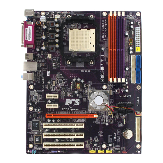
Page 10: Motherboard Components
Motherboard Components Introducing the Motherboard... - Page 11 Table of Motherboard Components LABEL COMPONENT Socket AM2 for AMD Sempron/Athlon 64/ 1 CPU Socket Athlon 64 X2 Dual-Core/Athlon 64 FX pro- cessors 2 CPU_FAN1 CPU cooling fan connector 3 DIMMA1/2~B1/2 240-pin DDR2 SDRAM slots 4 ATX1 Standard 24-pin ATX power connector 5 IDE2 Secondary IDE connector 6 IDE1...
- Page 12 Memo Introducing the Motherboard...
-
Page 13: Installing The Motherboard
Chapter 2 Installing the Motherboard Safety Precautions • Follow these safety precautions when installing the motherboard • Wear a grounding strap attached to a grounded device to avoid damage from static electricity • Discharge static electricity by touching the metal case of a safely grounded object before working on the motherboard •... -
Page 14: Checking Jumper Settings
Do not over-tighten the screws as this can stress the motherboard. Checking Jumper Settings This section explains how to set jumpers for correct configuration of the motherboard. Setting Jumpers Use the motherboard jumpers to set system configuration options. Jumpers with more than one pin are numbered. -
Page 15: Checking Jumper Settings
Checking Jumper Settings The following illustration shows the location of the motherboard jumpers. Pin 1 is labeled. Jumper Settings Jumper Type Description Setting (default) 1-2: NORMAL 2-3: CLEAR CLR_COMS 3-pin CLEAR CMOS Before clearing the CMOS, make sure to CLR_COMS turn the system off. -
Page 16: Connecting Case Components
Connecting Case Components After you have installed the motherboard into a case, you can begin con- necting the motherboard components. Refer to the following: Connect the CPU cooling fan cable to CPU_FAN1. Connect the case cooling fan connector to CAS_FAN1. Connect the system cooling fan connector to SYS_FAN1. - Page 17 CPU_FAN1: CPU Cooling FAN Power Connector Signal Name Function System Ground +12V Power +12V Sense Sensor CPU FAN control CAS_FAN1/SYS_FAN1: Cooling FAN Power Connectors Signal Name Function System Ground +12V Power +12V Sense Sensor SPK1: Internal speaker Signal Name Signal ATX1: ATX 24-pin Power Connector Signal Name Signal Name...
-
Page 18: Front Panel Header
Front Panel Header The front panel header (PANEL1) provides a standard set of switch and LED headers commonly found on ATX or Micro ATX cases. Refer to the table below for information: Pin Signal Name Function Pin Signal Name Function HD_LED_P Hard disk LED(+) 2 FP PWR/SLP *MSG LED(+) - Page 19 On most motherboards, there are small surface-mount resistors near the processor socket, which may be damaged if the cooling fan is carelessly installed. Avoid using cooling fans with sharp edges on the fan casing and the clips. Also, install the cooling fan in a well-lit work area so that you can clearly see the motherboard and processor socket.
-
Page 20: Installing Memory Modules
Installing Memory Modules This motherboard accommodates four 240-pin unbuffered DIMMs and supports DDR2 800 /667/533/400 DDR2 SDRAM. You must install at least one module in any of the four slots. Each module can be installed with 8 GB of memory; the total memory capacity is 32 GB. DDR2 SDRAM memory module table Memory module Memory Bus... - Page 21 Table A: Unbuffered DIMM Support for Socket AM2 CPU Output Driver DRAM Timing Address Timing DIMM1 DIMM2 Compensation Speed Mode Control Register Control Register DDR2-400 002F_2F2Fh X011_1222h DDR2-400 002F_2F2Fh X011_1322h DDR2-533 002F_2F2Fh X011_1222h SRx16 SRx16 SRx16 SRx8 DDR2-533 002F_2F2Fh X011_1322h SRx8 SRx16 DDR2-533...
-
Page 22: Installing A Hard Disk Drive/Cd-Rom/Sata Hard Drive
Installing a Hard Disk Drive/CD-ROM/SATA Hard Drive This section describes how to install IDE devices such as a hard disk drive and a CD-ROM drive. About IDE Devices Your motherboard has a primary and secondary IDE channel interface (IDE1 and IDE2). An IDE ribbon cable supporting two IDE devices is bundled with the motherboard. - Page 23 About SATA Connectors Your motherboard features four SATA connectors supporting a total of four drives. SATA refers to Serial ATA (Advanced Technology Attachment) is the standard interface for the IDE hard drives which are currently used in most PCs. These connectors are well designed and will only fit in one orientation.
-
Page 24: Installing A Floppy Diskette Drive
Installing a Floppy Diskette Drive The motherboard has a floppy diskette drive (FDD1) interface and ships with a diskette drive ribbon cable that supports one or two floppy diskette drives. You can install a 5.25- inch drive and a 3.5-inch drive with various capacities. The floppy diskette drive cable has one type of connector for a 5.25-inch drive and another type of connector for a 3.5-inch drive. - Page 25 PCIE2~3 Slots The two PCI Express x1 slots are fully compliant to the PCI Express Base Specification revision 1.0a as well. PCIE1 Slot The PCI Express x16 slot is used to install an external PCI Express graphics card that is fully compliant to the PCI Express Base Specifica- tion revision 1.0a.
-
Page 26: Connecting Optional Devices
Connecting Optional Devices Refer to the following for information on connecting the motherboard’s optional devices: AUDIO1: Front Panel Audio header This header allows the user to install auxiliary front-oriented microphone and line-out ports for easier access. Signal Name Signal Name Function AUD_MIC Front Panel Microphone input signal... - Page 27 SATA1~4: Serial ATA connectors These connectors are used to support the new Serial ATA devices for the highest date transfer rates (1.5 Gb/s), simpler disk drive cabling and easier PC assembly. It eliminates limitations of the current Parallel ATA interface. But maintains register compatibility and software compatibility with Parallel ATA.
- Page 28 SPDIFO1: SPDIF out header This is an optional header that provides an S/PDIF (Sony/Philips Digital Interface) output to digital multimedia device through optical fiber or coaxial connector. Signal Name Function SPDIF SPDIF digital output +5VA 5V analog Power No pin Ground Installing the Motherboard...
-
Page 29: Connecting I/O Devices
Connecting I/O Devices The backplane of the motherboard has the following I/O ports: (optional) PS2 Mouse Use the upper PS/2 port to connect a PS/2 pointing device. PS2 Keyboard Use the lower PS/2 port to connect a PS/2 keyboard. Parallel Port (LPT1) Use LPT1 to connect printers or other parallel communications devices. - Page 30 Memo Installing the Motherboard...
-
Page 31: Using Bios
Chapter 3 Using BIOS About the Setup Utility The computer uses the latest Award BIOS with support for Windows Plug and Play. The CMOS chip on the motherboard contains the ROM setup instructions for configuring the motherboard BIOS. The BIOS (Basic Input and Output System) Setup Utility displays the system’s configura- tion status and provides you with options to set system parameters. - Page 32 Press DEL to enter SETUP Pressing the delete key accesses the BIOS Setup Utility: Phoenix-Award WorkstationBIOS CMOS Setup Utility: Standard CMOS Features Load Fail-Safe Defaults Advanced BIOS Features Load Optimized Defaults Advanced Chipset Features Set Supervisor Password Integrated Peripherals Set User Password Save &...
-
Page 33: Updating The Bios
Updating the BIOS You can download and install updated BIOS for this motherboard from the manufacturer’s Web site. New BIOS provides support for new peripherals, improvements in performance, or fixes for known bugs. Install new BIOS as follows: If your motherboard has a BIOS protection jumper, change the setting to allow BIOS flashing. -
Page 34: Standard Cmos Features
Standard CMOS Features This option displays basic information about your system. Phoenix-Award WorkstationBIOS CMOS Setup Utility Standard CMOS Features Date (mm:dd:yy) Wed, Jan.1 2006 Item Help Time (hh:mm:ss) 0 : 54 : 28 IDE Channel 0 Master [None] Menu Level IDE Channel 0 Slave [None] Change the day, month,... - Page 35 IDE HDD Auto-Detection Press <Enter> while this item is highlighted to prompt the Setup Utility to automatically detect and configure an IDE device on the IDE channel. If you are setting up a new hard disk drive that supports LBA mode, more than one line will appear in the parameter box.
-
Page 36: Advanced Bios Features
Advanced BIOS Features This option defines advanced information about your system. Phoenix-Award WorkstationBIOS CMOS Setup Utility Advanced BIOS Features CPU Feature [Press Enter] Item Help Removable Device Priority [Press Enter] Hard Disk Boot Priority [Press Enter] CD-ROM Boot Priority [Press Enter] Menu Level Network Boot Priority [Press Enter]... - Page 37 NPT Fid control (Auto) This item allows users to adjust the CPU frequency; the range will be variedaccording to different CPUs. We strongly recommend you leave this item at its default value. NPT Vid control (Auto) This item allows users to adjust the CPU voltage. We strongly recommend you leave this item at its default value Removable Device Priority (Press Enter) Scroll to this item and press <Enter>...
- Page 38 CD-ROM Boot Priority (Press Enter) Scroll to this item and press <Enter> to view the following screen: Phoenix-Award WorkstationBIOS CMOS Setup Utility CD-ROM Boot Priority Item Help 1. Ch0 S. : LITE-ON DVD SOHD-16P9S Menu Level Use < > or < >...
- Page 39 First/Second/Third Boot Device (Removable/Hard Disk/CDROM) Use these three items to select the priority and order of the devices that your system searches for an operating system at start-up time. Boot Other Device (Enabled) When enabled, the system searches all other possible locations for an operating system if it fails to find one in the devices specified under the First, Second, and Third boot devices.
-
Page 40: Advanced Chipset Features
Advanced Chipset Features These items define critical timing parameters of the motherboard. You should leave the items on this page at their default values unless you are very familiar with the technical specifications of your system hardware. If you change the values incorrectly, you may introduce fatal errors or recurring instability into your system. - Page 41 DRAM Configuration (Press Enter) Scroll to this item and press <Enter> to view the following screen: Phoenix-Award WorkstationBIOS CMOS Setup Utility DRAM Configuration Item Help Timing Mode [Auto] Memory Clock value or Limi DDR 400 Menu Level Places an artificial memory clock limit on the system.
-
Page 42: Integrated Peripherals
Integrated Peripherals These options display items that define the operation of peripheral components on the system’s input/output ports. Phoenix-Award WorkstationBIOS CMOS Setup Utility Integrated Peripherals Item Help IDE Function Setup [Press Enter] RAID Config [Press Enter] Onboard Device [Press Enter] SuperIO Device [Press Enter] IDE HDD Block Mode... - Page 43 Primary/Secondary Master/Slave UltraDMA (Auto) Each IDE channel supports a master device and a slave device. This motherboard supports UltraDMA technology, which provides faster access to IDE devices. If you install a device that supports UltraDMA, change the appropriate item on this list to Auto.
- Page 44 Onboard Device (Press Enter) Scroll to this item and press <Enter> to view the following screen: Phoenix-Award WorkstationBIOS CMOS Setup Utility Onboard Device Onchip USB [V1.1 + V2.0] Item Help USB Legacy Support [Enabled] USB Mouse Support [Enabled] Menu Level AC97 Audio [Auto] Onboard Lan...
- Page 45 SuperIO Device (Press Enter) Scroll to this item and press <Enter> to view the following screen: Phoenix-Award WorkstationBIOS CMOS Setup Utility SuperIO Device Item Help Onboard FDC Controller [Enabled] Onboard Serial Port 1 [3F8/IRQ4] UART Port [Disabled] Menu Level UART Mode Select IrDA UR2 Duplex Mode Half...
-
Page 46: Power Management Setup
ECP Mode Use DMA (3) When the onboard parallel port is set to ECP mode, the parallel port can use DMA 3 or DMA 1. Press <Esc> to return to the Integrated Peripherals page. IDE HDD Block Mode (Enabled) Enables this field if your IDE hard drive supports block mode. Block mode enables BIOS to automatically detect the optimal number of block read and writes per sector that the drive can support and improves the speed of access to IDE devices. -
Page 47: Pnp/Pci Configurations
Soft-Off by PBTN (Instant-Off) Under ACPI (Advanced Configuration and Power management Interface) you can create a software power down. In a software power down, the system can be resumed by Wake Up Alarms. This item lets you install a software power down that is controlled by the power button on your system. - Page 48 Init Display First (PCI Slot) This item allows you to choose the primary display card. Reset Configuration Data (Disabled) If you enable this item and restart the system, any Plug and Play configuration data stored in the BIOS Setup is cleared from memory. Resources Controlled By (Auto(ESCD)) You should leave this item at the default Auto (ESCD).
-
Page 49: Pc Health Status
PC Health Status On motherboards that support hardware monitoring, this item lets you monitor the parameters for critical voltages, temperatures and fan speeds. Phoenix-Award WorkstationBIOS CMOS Setup Utility PC Health Status Smart Fan Function [Press Enter] Item Help Shutdown Temperature [Disabled]] Warning Temperature [Disabled]... - Page 50 • FAN1 START PWM VALUE: This item is used to set the start PWM value of the smart fan. • FAN1 START Temp C: This item is used to set the start temperature of the smart fan. • FAN1 Limit Temp This item is used to set the limit temperature of the smart fan.
-
Page 51: Load Fail-Safe Defaults
Load Fail-Safe Defaults This option opens a dialog box that lets you install fail-safe defaults for all appropriate items in the Setup Utility: Press <Y> and then <Enter> to install the defaults. Press <N> and then <Enter> to not install the defaults. The fail-safe defaults place no great demands on the system and are generally stable. -
Page 52: Save & Exit Setup
Save & Exit Setup Highlight this item and press <Enter> to save the changes that you have made in the Setup Utility and exit the Setup Utility. When the Save and Exit dialog box appears, press <Y> to save and exit, or press <N> to return to the main menu. Exit Without Saving Highlight this item and press <Enter>... -
Page 53: Using The Motherboard Software
Chapter 4 Using the Motherboard Software About the Software CD-ROM The support software CD-ROM that is included in the motherboard package contains all the drivers and utility programs needed to properly run the bundled products. Below you can find a brief description of each software program, and the location for your motherboard version. -
Page 54: Running Setup
Setup Tab Setup Click the Setup button to run the software installation program. Select from the menu which software you want to install. Browse CD The Browse CD button is the standard Windows command that allows you to open Windows Explorer and show the contents of the support Before installing the software from Windows Explorer, look for a file named README.TXT, INSTALL.TXT or something similar. - Page 55 Click Next. The following screen appears: Check the box next to the items you want to install. The default options are recommended. Click Next run the Installation Wizard. An item installation screen appears: Follow the instructions on the screen to install the items. Drivers and software are automatically installed in sequence.
-
Page 56: Manual Installation
Manual Installation Insert the CD in the CD-ROM drive and locate the PATH.DOC file in the root directory. This file contains the information needed to locate the drivers for your motherboard. Look for the chipset and motherboard model; then browse to the directory and path to begin installing the drivers. - Page 57 Caractéristiques Processeur Cette carte mère utilise un socket AM2 ayant les caractéristiques suivantes : • Peut recevoir les processeurs AMD Sempron/Athlon 64/Athlon 64 X2 double noyau/Athlon 64 FX • Prend en charge des vitesses d’interface HyperTransport (HT) allant jusqu’à 2000MT/s La Technologie HyperTransport est une liaison point à...
- Page 58 Options d’extension La carte mère est livrée avec les options d’extensions suivantes: • Un logement PCI Express x16 • Deux logements PCI Express x1 • Trois emplacements PCI v2.3 32bits • Deux embases IDE prenant en charge quatre périphériques IDE •...
- Page 59 Feature Prozessor Dieses Mainboard verwendet einen AM2-Sockel mit den folgenden Eigenschaften: • Nimmt AMD Sempron/Athlon 64/Athlon 64 X2 Dual-Core/Athlon 64 FX- Prozessoren auf • Unterstützt bis zu 2000MT/s HyperTransport (HT) Interface- Geschwindigkeiten HyperTransport Technologie ist ein Punkt-zu-Punkt Link zwischen zwei Geräten. Es ermöglicht integrierten Schaltkreisen einen Informationsaustausch mit wesentlich höherer Geschwindigkeit als bei gängigen Interconnect-Technologien.
- Page 60 Erweiterungsoptionen Das Mainboard bietet die folgenden Erweiterungsoptionen: • Ein PCI Express x16 Steckplatz • Zwei PCI Express x1 Steckplätze • Drei 32-bit PCI v2.3-Steckplätze • Zwei IDE-Header, die vier IDE-Geräte unterstützen • Ein Steckplatz für ein Diskettenlaufwerk • Vier 7-Pin SATA-Stecker Dieses Mainboard unterstützt Ultra DMA Bus-Mastering mit Transferraten von 133/100/66MB/ Integrierte I/O-Schnittstellen Das Mainboard verfügt über einen kompletten Satz von I/O-Schnittstellen und Anschlüssen:...
- Page 61 Caratteristiche Processore La scheda madre utilizza una presa AM2 pin che offre le seguenti caratteristiche: • Adatta i processori AMD Sempron/Athlon 64/Athlon 64 X2 Dual-Core/ Athlon 64 FX • Supporto di velocità di interfaccia HyperTransport (HT) fino a 2000 MT/s La tecnologia HyperTransport consente il collegamento point-to-point fra due dispositivi e quindi un trasferimento di informazioni tra circuiti integrati molto più...
- Page 62 Opzioni di espansione La scheda madre è dotata delle seguenti opzioni di espansione: • Uno slot PCI Express x16 • Due slot PCI Express x1 • Tre slot PCI v2.3 a 32 bit • Due connettori IDE per il supporto di 4 componenti IDE •...
- Page 63 Característica Procesador Esta placa principal usa Socket AM2 que ofrece las sigtes. características: • Acomoda procesadores AMD Sempron/Athlon 64/Athlon 64 X2 Dual-Core/ Athlon 64 FX • Soporta hasta las velocidades de interfaz 2000MT/s HyperTransport (HT) La Tecnología HyperTransport es un vínculo punto a punto entre dos dispositivos, habilita circuitos integrados para intercambiar la información en velocidades más rápidas que las tecnologías de interconexión disponibles actualmente.
- Page 64 Opciones de Expansión La placa principal viene con las sigtes. opciones de expansión: • Una ranura PCI Express x16 • Dos ranuras PCI Express x1 • Tres ranuras conforme con 32-bit PCI v2.3 • Dos cabezales IDE que soporta cuatro dispositivos IDE •...
- Page 65 Características Processador Esta motherboard usa Ficha AM2 que possui as seguintes características: • Acomoda processadores de núcleo duplo AMD Sempron/Athlon 64/Athlon 64 X2/Athlon 64 FX • Suporta velocidades de interface de HyperTransport (HT) até 2000MT/s Tecnologia de HyperTransport Té um link ponto-a-ponto entre dois dispositivos, permite circuitos integrados para trocar informação a velocidades muito mais elevadas que as disponíveis actualmente em tecnologias de interconexão.
- Page 66 Opções de Expansão A motherboard é fornecida com as seguintes opções de expansão: • Uma ranhura PCI Express x16 • Duas ranhuras PCI Express x1 • Três ranhuras compatíveis com PCI v2.3 de 32 bits • Dois colectores IDE que suportam quatro dispositivos IDE •...
- Page 67 機能 プロセッサ このマザーボードには、次の機能を持ったソケット AM2があります: • AMD Sempron/Athlon 64/Athlon 64 X2 Dual-Core/Athlon 64 FX プロ セッサに対応 • 転送率が最大2000MT/秒までの HyperTransport (HT)インターフェース を採用 HyperTransport 技術とは、二つのデバイスを1対1( point-to-point)で接続する技 術であり、従来のインターコネクト技術に比較して、集積回路同士の情報交換を高速化 します。 チップセット NVIDIA® nForce4-4X はシングルチップのもので、実証済みの信頼性と高性能性を提 供します。 • HyperTransport x16でAMD Sempron/Athlon 64/Athlon 64 X2 Dual- Core/Athlon 64 FX プロセッサとの1.0 GHzのアッププリンクとダウンリンク...
- Page 68 拡張オプション 本マザーボードでは、次の拡張機能が利用できます。 • PCI Express x16 スロット x1 • PCI Express x1 スロット x2 • 32ビットPCI v2.3 互換性スロット x3 • IDEヘッダー x2 (4つのIDEデバイスの接続を可能) • フロッピーディスクドライブインターフェイス x1 • 7ピンSATAコネクタ X4 このマザーボードは、133/100/66MB/秒の転送速度でのUltra DMAバスマスタリングを サポートします。 統合の入出力ポート マザーボードには、次のI/Oポートやコネクタを揃えています。 • マウスとキーボード用のPS/2ポート x2 • シリアルポート x1 •...
- Page 69 특성 프로세서 본 마더보드에 탑재된 소켓 AM2는 다음과 같은 기능을 제공한다: • AMD 샘프론/애슬론 64/애슬론 64 X2 듀얼 코어/애슬론 64 FX 프로세서 탑재 • HyperTransport (HT) 인터페이스 속도 최대 2000MT/s 지원 HyperTransport 기술은 두 장치간의 point-to-point 링크로, 집적 회로가 기존의 상호...
- Page 70 확장 옵션 본 마더보드의 확장 옵션은 다음과 같다: • PCI Express x16 슬롯 1 개 • PCI Express x1 슬롯 2 개 • 32 비트 PCI v2.3 호환 슬롯 3 개 • 4 개의 IDE 장치를 지원하는 IDE 헤더 2 개 •...
- Page 71 功能 處理器 此主機板使用具有如下特性的Socket AM2 插槽: ‧ 適用 AMD Sempron/Athlon 64/Athlon 64 X2 Dual-Core/Athlon 64 FX 處理器; ‧ 支援高達2000MT/秒的HyperTransport (HT)介面傳輸速率。 HyperTransport 技術為以點對點方式連接兩台設備的技術,藉此,積體電路間能夠以 後高於現有各種內部連接技術(interconnect technology)技術的速度來交換資訊。 晶片組 NVIDIA® nForce4-4X 採單晶片設計,具有令人贊賞的可靠性及效能。 ‧ HyperTransport x16,其提供對AMD Sempron/Athlon 64/Athlon 64 X2 Dual-Core/ Athlon 64 FX 處理器高達1.0GHz上行及下行連接; ‧ 2.3介面,其支援高達5個PCI插槽;...
- Page 72 擴充選項 本主機板包括下列擴充選項: ‧ 1個PCI Express x16插槽 ‧ 2個PCI Express x1 插槽 ‧ 3 個32位元PCIv2.3插槽; ‧ 2 個 IDE 接頭,支援 4個 IDE 裝置; ‧ 1 個軟碟機介面; ‧ 4個7針SATA插頭。 本主機板支援傳輸率133/100/66 MB/秒下的Ultra DMA 匯流排主控功能。 整合 I/O 主機板具有一組齊全的 I/O 連接埠及連接頭: • 2 個 PS/2 埠,供滑鼠與鍵盤使用; •...
- Page 73 功能 处理器 主板使用一个 Socket AM2 插座,此插座具有以下特点: • 支持 AMD Sempron/Athlon 64/Athlon 64 X2 双核/Athlon 64 FX 处理器 • 支持 2000MT/s HyperTransport (HT) 接口速度 HyperTransport 技术是一种在两台设备间进行点到点连接的技术,它可以让集成电 路使用比当前互连技术更高的速度进行信息交换。 芯片组 NVIDIA® nForce4-4X 是一种能提供高可靠性和高性能的单芯片。 • HyperTransport x16 技术,到 AMD Sempron/Athlon 64/Athlon 64 X2 双 核/Athlon 64 FX 处理器...
- Page 74 扩展选项 此主板提供如下扩展选项: • 1 个 PCI Express x16 插槽 • 2 个 PCI Express x1 插槽 • 3 个 32 位 PCI v2.3 扩展槽 • 2 个 IDE 接口,可支持 4 个 IDE 设备 • 1 个 软驱接口 • 4 个 7-pin SATA 接口 主板支持...
- Page 75 Характеристики Процессор Данная материнская плата размещает сокет AM2 и обладает следующими характеристиками: • Размещает процессоры AMD Sempron/Athlon 64/Athlon 64 X2 Dual- Core /Athlon 64 FX • Поддерживает технологию 2000MT/s HyperTransport (HT) Технология HyperTransport обеспечивает связь двух устройств по протоколу point- to-point, позволяя...
- Page 76 Возможности расширения Существуют следуюшие опции расширения данной материнской платы: • Один слот PCI Express x16 • Два слота PCI Express x1 • Три 32-битных слота PCI v2.3 • Два разъема IDE с поддержкой четырех устройств IDE • Один разъем для накопителя на гибких дисках •...
- Page 77 Cechy Procesor Ta płyta główna wyposażona jest w gniazdo AM2 i posiada następujące właściwości: • Przystosowany do procesorów AMD Sempron/Athlon 64/Athlon 64 X2 Dual-Core /Athlon 64 FX • Obsługuje złącze HyperTransport (HT) z szybkością do 2000MT/s Technologia HiperTransportu jest protokołem komunikacji między dwoma urządzeniami, który umożliwia układom zcalonym wymieniać...
- Page 78 Możliwości rozbudowy Płyta głwna wyposażona jest w następujące gniazda: • Jedno gniazdo PCI Express x16. • Dwa gniazda PCI Express x1 • Trzy 32-bitowych gniazda zgodnych z PCI w wersji 2.3 • Dwa złącza IDE obsługujące cztery urządzenia IDE. • Jedno złącze obsługujące stacje dyskietek •...
- Page 79 Vlastnosti Procesor Tato základní deska využívá patici Socket AM2 nabízející následující vlastnosti: • Podpora procesoru AMD Sempron/Athlon 64/Athlon 64 X2 Dual-Core/ Athlon 64 FX • Podpora rychlostí rozhraní HyperTransport (HT) až 2000 MT/s Technologie HyperTransport je přímým spojením mezi dvěma zařízeními, umožňující integrovaným obvodům výměnu informací...
- Page 80 Možnosti rozšíření Základní deska je dodávána s následujícími možnostmi rozšíření • Jedna patice PCI Express x16 pro grafickou kartu • Dva patice PCI Express x1 • Tři 32bitové patice PCI v2.3 • Dva 40kolíkový konektor IDE podporující až čtyři zařízení IDE •...
- Page 81 Caracteristici Procesorul Această placă de bază suportă un socket AM2 care are următoarele caracteristici: • Este compatibil cu procesoarele AMD Sempron/Athlon 64/Athlon 64 X2 Dual-Core/Athlon 64 FX • Suportă interfeţe HyperTransport (HT) cu viteze de până la 2000 MT/s Tehnologia HyperTransport este o legătură...
- Page 82 Opţiuni de extindere Placa de bază este dotată următoarele posibilităţi de extindere: • Un slot PCI Express de 16x • Două sloturi PCI Express de 1x • Trei sloturi de 32 biţi compatibile PCI, versiunea 2.3 • Două conectoare IDE care suportă patru unităţi IDE •...
- Page 83 Спецификация Процесор Тази дънна платка използва сокет AM2 със следните спецификации: • Поддръжка на процесори AMD Sempron/Athlon 64/Athlon 64 X 2 Dual- Core/Athlon 64 FX • Поддръжка на технологията HyperTransport (HT) със скорост до 2000MT/s Технологията HyperTransport е връзка точка-до-точка (point-to-point) между две...
- Page 84 Възможности за разширяване Дънната платка има следните разширителни възможности: • Един слот PCI Express x16 • Два слота PCI Express x1 • три слота 32-bit PCI v2.3 • Два колектора IDE с поддръжка на четири IDE устройства • един конектор за флопидисково устройство •...
- Page 85 Jellemző Processzor Ez az alaplap az alábbi jellemzőkkel biró AM2 socket-el van ellátva: • Összeegyeztethető azs AMD Sempron/Athlon 64/Athlon 64 X2 Dual-Core/ Athlon 64 FX processzorokkal • Maximum 2000 MT/s HyperTransport (HT) sebességű interfészt támogat A HyperTransport technológia egy ponttól pontig való kapcsolat két készülék között, és segítségével az integrált áramkörök közötti információcsere sebessége sokkal nagyobb, mint a jelenleg rendelkezésre álló...
- Page 86 Bővítési lehetőségek Az alaplap a következő bővítési lehetőségekkel rendelkezik: • Egy 16-szoros PCI Express foglalat • Két 1-szeres PCI Express foglalat • Három 32 bites, a PCI 2.3-as változatával kompatibilis foglalat • Két IDE csatlakozó négy IDE eszköz támogatására • Egy hajlékonylemez meghajtó...
Need help?
Do you have a question about the NFORCE4M-A and is the answer not in the manual?
Questions and answers