Table of Contents
Advertisement
Copyright
This publication, including all photographs, illustrations and software, is protected
under international copyright laws, with all rights reserved. Neither this manual, nor
any of the material contained herein, may be reproduced without written consent of
the author.
Version 1.0
Disclaimer
The information in this document is subject to change without notice. The manufac-
turer makes no representations or warranties with respect to the contents hereof
and specifically disclaims any implied warranties of merchantability or fitness for
any particular purpose. The manufacturer reserves the right to revise this publica-
tion and to make changes from time to time in the content hereof without obligation
of the manufacturer to notify any person of such revision or changes.
Trademark Recognition
Microsoft, MS-DOS and Windows are registered trademarks of Microsoft Corp.
MMX, Pentium, Pentium-II, Pentium-III, Celeron are registered trademarks of Intel
Corporation.
Other product names used in this manual are the properties of their respective owners
and are acknowledged.
Federal Communications Commission (FCC)
This equipment has been tested and found to comply with the limits for a Class B
digital device, pursuant to Part 15 of the FCC Rules. These limits are designed to
provide reasonable protection against harmful interference in a residential instal-
lation. This equipment generates, uses, and can radiate radio frequency energy and,
if not installed and used in accordance with the instructions, may cause harmful
interference to radio communications. However, there is no guarantee that interfer-
ence will not occur in a particular installation. If this equipment does cause harmful
interference to radio or television reception, which can be determined by turning
the equipment off and on, the user is encouraged to try to correct the interference by
one or more of the following measures:
•
Reorient or relocate the receiving antenna
•
Increase the separation between the equipment and the receiver
•
Connect the equipment onto an outlet on a circuit different from that to
which the receiver is connected
•
Consult the dealer or an experienced radio/TV technician for help
Shielded interconnect cables and a shielded AC power cable must be employed with
this equipment to ensure compliance with the pertinent RF emission limits govern-
ing this device. Changes or modifications not expressly approved by the system's
manufacturer could void the user's authority to operate the equipment.
BAT-I2 USER MANUAL
Preface
i
Advertisement
Table of Contents

Subscribe to Our Youtube Channel
Related Manuals for ECS BAT-I2


Summary of Contents for ECS BAT-I2
- Page 1 Shielded interconnect cables and a shielded AC power cable must be employed with this equipment to ensure compliance with the pertinent RF emission limits govern- ing this device. Changes or modifications not expressly approved by the system’s manufacturer could void the user’s authority to operate the equipment. BAT-I2 USER MANUAL...
-
Page 2: Declaration Of Conformity
Provides information on us- page 25 Using BIOS ing the BIOS Setup Utility. Chapter 4 Describes the motherboard page 51 software. Using the Motherboard Software Chapter 5 page 55 Provides basic trouble shoot- Trouble Shooting ing tips. BAT-I2 USER MANUAL... -
Page 3: Table Of Contents
The Standard Configuration............25 Entering the Setup Utility............25 Resetting the Default CMOS Values........26 Using BIOS..................26 BIOS Navigation Keys..............27 Main Menu................28 Advanced Menu..............28 Chipset Menu................42 M.I.B III (MB Intelligent BIOS III) Menu........44 Security Menu.................46 Boot Menu................47 Exit Menu................49 Updating the BIOS.................50 BAT-I2 USER MANUAL... - Page 4 Using the Motherboard Software Auto-installing under Windows 7/8/8.1........51 ..Running Setup..............51 Manual Installation................53 ECS Utility Software (Intelligent EZ Utility) (Optional)....53 Chapter 5 Trouble Shooting Start up problems during assembly..........55 Start up problems after prolong use..........56 Maintenance and care tips..............56 Basic Troubleshooting Flowchart...........57...
-
Page 5: Introducing The Motherboard
Chapter 1 Introducing the Motherboard Introduction Thank you for choosing the BAT-I2 motherboard. This motherboard is a high perfor- ® mance, enhanced function. This motherboard has onboard Intel Bay Trail-D J1750/ J1800/J1850/J1900/J2850/J2900 SOC for high-end business or personal desktop mar- kets. -
Page 6: Specifications
® • Onboard Intel Bay Trail-D J1750/J1800/J1850/J1900/J2850/ J2900 SOC Note: Please go to ECS website for the latest CPU support list. Memory • Signal channel DDR3 SO-DIMM memory architecture • 1 x 204-pin DDR3 SO-DIMM socket supports up to 8 GB •... - Page 7 /eDLU/eSF Software • 3rd Party Bundled Software: Cyberlink* /Norton* /Muzee* Support Note: Microsoft .NET Framework 3.5 is required. Free bundle software is including ECS DVD: Cyberlink/ Norton/Muzee Form Factor • Mini ITX Size, 170mm x 170mm BAT-I2 USER MANUAL...
-
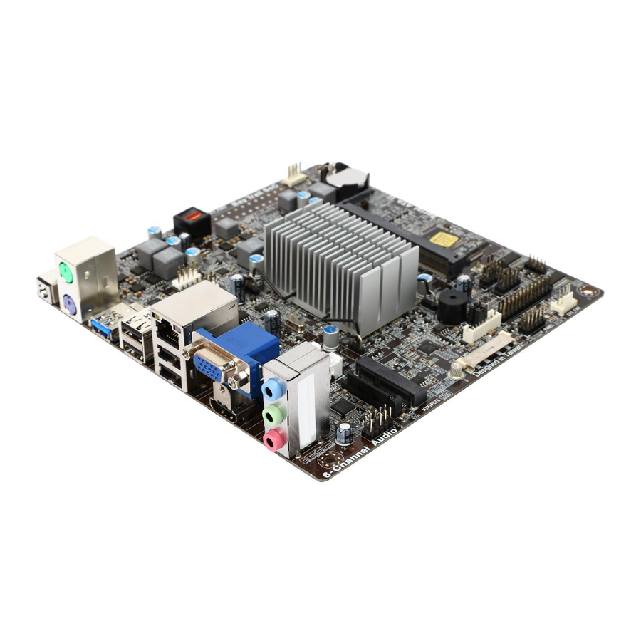
Page 8: Motherboard Components
Motherboard Components BAT-I2 USER MANUAL... - Page 9 PCIE (half card) slot 17. SATA_PWR SATA power connector (optional) 18. F_AUDIO Front panel audio header 19. SATA1~2 Serial ATA 3Gb/s connectors 20. F_USB1~2 Front panel USB 2.0 headers 21. ATX19V 4-pin +19V power connector (optional) BAT-I2 USER MANUAL...
-
Page 10: I/O Ports
It can be connected to an external CD/DVD player, Tape player or other audio devices for audio input. 10. Line-out (lime) It is used to connect to speakers or headphones. 11. Microphone (pink) It is used to connect to a microphone. BAT-I2 USER MANUAL... -
Page 11: Installing The Motherboard
Place the motherboard over the mounting brackets and secure the motherboard onto the mounting brackets with screws. Do not over-tighten the screws as this can stress the motherboard. BAT-I2 USER MANUAL... -
Page 12: Checking Jumper Settings
The following illustration shows the location of the motherboard jumpers. Pin 1 is labeled. To avoid the system instability after clearing CMOS, we recommend users to enter the main BIOS setting page to “Load Default Settings” and then “Save and Exit Setup”. BAT-I2 USER MANUAL... - Page 13 2. LCD_PWR: LVDS Select Jumper (optional) 3. BKLT_PWR: Backlight Select Jumper (optional) BAT-I2 USER MANUAL...
-
Page 14: Installing Hardware
Refer to the following to install the memory modules. Install the DIMM module into the slot and press it firmly down until it seats correctly. Check that the cutouts on the DIMM module edge connector match the notches in the DIMM slot. DIMM1 BAT-I2 USER MANUAL... -
Page 15: Installing Add-On Cards
The mini PCIE (half-card) supports extension cards with PCIE signal. Slot Before installing an add-on card, check the documentation for the card carefully. If the card is not Plug and Play, you may have to manually configure the card before installation. BAT-I2 USER MANUAL... - Page 16 Follow these instructions to install a wireless card or TV tuner card: Insert a wireless card or TV tuner card into the miniPCIE Slot. Lower the handle and tighten the screws. BAT-I2 USER MANUAL...
-
Page 17: Connecting Optional Devices
F_AUDIO SATA1~2 F_USB1~2 DISP_BRT (optional) 1. CASE: Chassis Intrusion Detect Header This detects if the chassis cover has been removed. This functiion needs a chassis equipped with intrusion detection switch and needs to be enabled in BIOS. BAT-I2 USER MANUAL... - Page 18 2. COM1~2: Onboard Serial Port Headers Connect serial port extension brackets to these headers to add serial ports to your system. 3. LDC: Debug Card Header BAT-I2 USER MANUAL...
- Page 19 4. LPT: Onboard Parallel Port Header This header can be used to connect to the printer, scanner or other devices. 5. DISP_BRT: LVDS Brightness Control Header (optional) BAT-I2 USER MANUAL...
- Page 20 2. Due to the chipset limitation, using dual displays LVDS(AIO) + VGA or LVDS(AIO) + HDMI will cause the problem that you may not enter BIOS setup or have the display problem. BAT-I2 USER MANUAL...
- Page 21 97 Front Panel, please tick off the option of “ Disabled Front Panel Detect ”. If you use HD Audio Front Panel, please don’ t tick off “Disabled Front Panel Detect ” . * For reference only BAT-I2 USER MANUAL...
- Page 22 8. SATA1~2: Serial ATA Connectors SATA 1~2 connectors support the Serial ATA 3Gb/s device, simpler disk drive cabling and easier PC assembly. It eliminates limitations of the current Parallel ATA interface. But maintains register compatibility and software compatibility with Parallel ATA. BAT-I2 USER MANUAL...
- Page 23 USB 2.0 connector to connect the front-mounted ports to the motherboard. Please make sure that the USB cable has the same pin assignment as indicated above. A different pin assignment may cause damage or system hang-up. BAT-I2 USER MANUAL...
-
Page 24: Installing A Sata Hard Drive
Attach either cable end to the connector on the motherboard. Attach the other cable end to the SATA hard drive. Attach the SATA power cable to the SATA hard drive and connect the other end to the power supply. * For reference only BAT-I2 USER MANUAL... -
Page 25: Connecting Case Components
SATA_PWR (optional) SYS_FAN ATX19V (optional) 1 & 6. ATX_POWER (ATX 24-pin Power Connector) (optional) & ATX19V (ATX19V Power Connector) (optional) Connect the standard power supply connector to ATX_POWER. Connect the auxiliary case power supply connector to ATX19V. BAT-I2 USER MANUAL... - Page 26 ~ 2.2A (26.4W max) at +12V. 4. F_PANEL: Front Panel Header The front panel header (F_PANEL) provides a standard set of switch and LED headers commonly found on ATX or Micro ATX cases. Refer to the table below for information: BAT-I2 USER MANUAL...
- Page 27 After receiving a power on/off signal, at least two seconds elapses before the power supply recognizes another on/off signal. 5. SATA_PWR: SATA power connector (optional) This concludes Chapter 2. The next chapter covers the BIOS. BAT-I2 USER MANUAL...
- Page 28 Memo BAT-I2 USER MANUAL...
-
Page 29: Using Bios
When you power on the system, BIOS enters the Power-On Self Test (POST) routines. POST is a series of built-in diagnostics performed by the BIOS. After the POST routines are completed, the following message appears: Press DEL to enter SETUP BAT-I2 USER MANUAL... -
Page 30: Resetting The Default Cmos Values
Other options lead to dialog boxes that prompt you for information. Some options (marked with a triangle ) lead to submenus that enable you to change the values for the option. Use the cursor arrow keys to scroll through the items in the submenu. BAT-I2 USER MANUAL... -
Page 31: Bios Navigation Keys
BIOS items presented in this manual. The BIOS setup screens shown in this chapter are for reference only and may differ from the actual BIOS. Please visit the manufacture’s website for updated manual. BAT-I2 USER MANUAL... -
Page 32: Main Menu
:Select Item USB Configuration Enter : Select Inetl (R) Smart Connect Technology +/- : Change Opt. Super IO Configuration F1:General Help F2:Previous Values F3:Optimized Defaults F4:Save & Exit ESC:Exit Version 2.16.1242. Copyright (C) 2013 American Megatrends, Inc. BAT-I2 USER MANUAL... -
Page 33: Lan Configuration
Onboard LAN Controller (Enabled) Use this item to enable or disable the Onboard LAN. Network Stack (Disabled) Use this item to enable or disable the UEFI Network Stack. Press <Esc> to return to the Advanced Menu page. BAT-I2 USER MANUAL... -
Page 34: Pc Health Status
F4:Save & Exit ESC:Exit Version 2.16.1242. Copyright (C) 2013 American Megatrends, Inc. CPU/System Smart FAN Control (Enabled) This item allows you to enable or disable the control of the CPU/system fan speed by changing the fan voltage. BAT-I2 USER MANUAL... - Page 35 System & CPU temperature, CPU & DIMM voltage, CPU & system fan speed,... etc. • System Temperature • CPU Fan Speed • System Fan Speed • CPU Voltage • DIMM Voltage Press <Esc> to return to the Advanced Menu page. BAT-I2 USER MANUAL...
-
Page 36: Power Management Setup
EUP Function (Enabled) This item allows user to enable or disable EUP support. Power LED Type (Dual Color LED) This item shows the type of the Power LED. Press <Esc> to return to the Advanced Menu page. BAT-I2 USER MANUAL... -
Page 37: Pci Express Configuration
ESC:Exit Version 2.16.1242. Copyright (C) 2013 American Megatrends, Inc. ACPI Sleep State (S3(Suspend to RAM)) This item allows user to enter the ACPI S3 (Suspend toRAM) Sleep State(default). Press <Esc> to return to the Advanced Menu page. BAT-I2 USER MANUAL... -
Page 38: Cpu Configuration
Version 2.16.1242. Copyright (C) 2013 American Megatrends, Inc. Intel(R) Celeron(R) CPU J1800 @ 2.41GHZ This is display-only field and displays the information of the CPU installed in your computer. CPU Signature (30673) This item shows the information of the CPU signature. BAT-I2 USER MANUAL... - Page 39 If you enable this item, the processor fetches the currently requested cache line, as well as the subsequent cache line. This reduces the cache latency by making the next cache line immediately avaiable if the processor requires it as well. BAT-I2 USER MANUAL...
- Page 40 This item enables or disables the power management features. Enhanced Halt (C1E) (Enabled) Use this item to enable the CPU energy-saving function when the system is not running. Press <Esc> to return to the Advanced Menu page. BAT-I2 USER MANUAL...
-
Page 41: Sata Configuration
SATA Port1/2 (Not Present) This motherboard supports two SATA channels, and each channel allows one SATA device to be installed. These items will display the information of devices installed. Press <Esc> to return to the Advanced Menu page. BAT-I2 USER MANUAL... -
Page 42: Usb Configuration
F2:Previous Values F3:Optimized Defaults F4:Save & Exit ESC:Exit Version 2.16.1242. Copyright (C) 2013 American Megatrends, Inc. ISCT Support (Disabled) Use this item to enable or disable ISCT Support. Press <Esc> to return to the Advanced Menu page. BAT-I2 USER MANUAL... -
Page 43: Super Io Configuration
This item allows you to enable or disable serial port. Device Settings (IO=3F8h; IRQ=4) This item shows the information of the device settings. Change Settings (Auto) Use this item to change device settings. Press <Esc> to return to the Super IO Configuration page. BAT-I2 USER MANUAL... - Page 44 This item allows you to enable or disable serial port. Device Settings (IO=2F8h; IRQ=3) This item shows the information of the device settings. Change Settings (Auto) Use this item to change device settings. Press <Esc> to return to the Super IO Configuration page. BAT-I2 USER MANUAL...
- Page 45 Use this item to change device settings. Device Mode (Standard Parallel...) This item is used for Printer port mode selection, it can be set to Standard Parallel Port Mode (SPP) or EPP Mode. Press <Esc> to return to the Super IO Configuration page. BAT-I2 USER MANUAL...
-
Page 46: Chipset Menu
This item shows the information of DVMT 5.0 total graphic memory size used by Internal Graphics Device. Restore AC Power Loss (Power Off) This item enables your computer to automatically restart or return to its operating status. Azalia HD Audio (Enabled) This item enables or disables Azalia HD audio. BAT-I2 USER MANUAL... - Page 47 This item shows the Sec Reference Code Version. TXE FW Version (01.00.02.1060) This item shows the TXE Firmware Version. TXE Mode (Enabled) This is TXE mode control item, it is used to enable or disable the TXE firmware. BAT-I2 USER MANUAL...
-
Page 48: Mb Intelligent Bios Iii) Menu
This is display-only field and displays the information of the CPU installed in your computer. CPU Speed (2.41 GHz) This item shows the CPU speed. Memory Frequency (1333 MHz) This item shows the memory frequency. Total Memory (2048 MB (LPDDR3)) This item shows the total memory. BAT-I2 USER MANUAL... - Page 49 Memory Voltage Configuration (Auto) This item provides 3 configuration modes for the voltage of memory modules. Auto: Always provide DDR3L standard voltage (1.35V). Low Voltage: Provide the lowest voltage memory module supported. Manual: User customized (provide 1.35V or 1.50V). BAT-I2 USER MANUAL...
-
Page 50: Security Menu
This item shows system of secure boot (can be setup or user). Secure Boot (Not Active) This item shows the active state of secure boot. Secure Boot (Disabled) Use this item to enable or disable secure boot state. BAT-I2 USER MANUAL... -
Page 51: Boot Menu
This item enables you to set boot priority for all boot devices. Boot Option #1/ 2/ 3/ 4/ 5/ 6 /7 These items show the boot priorities and can be used to set the boot priorities of various device categories. BAT-I2 USER MANUAL... - Page 52 Set the order of these items to set the boot priorities of device of certain device category (Hard Disk Drive, USB Flash Drive, and etc.). Boot option #1 will be the first priority, Boot option #2 will be the second, and so on. BAT-I2 USER MANUAL...
-
Page 53: Exit Menu
Use this item enables you to save the changes that you have made as user defaults. Restore User Defaults Use this item enables you to restore user defaults to all the setup options. Boot Override Use this item enables you to set the device order. BAT-I2 USER MANUAL... -
Page 54: Updating The Bios
BIOS jumper, reset the jumper to protect the newly installed BIOS from being overwritten. The computer will restart automatically. This concludes Chapter 3. Refer to the next chapter for information on the software supplied with the motherboard. BAT-I2 USER MANUAL... -
Page 55: Bat-I2 User Manual
Click Setup. The installation program begins: The following screens are examples only. The screens and driver lists will be different according to the motherboard you are installing. The motherboard identification is located in the upper left-hand corner. BAT-I2 USER MANUAL... - Page 56 Windows 8 will show the following screen after system restart, you must select “Desktop” in the bottom left to install the next driver. BAT-I2 USER MANUAL...
-
Page 57: Manual Installation
ECS Utility Software (Intelligent EZ Utility) (Optional) ECS Intelligent EZ Utility provides friendly interfaces under Windows O.S, which makes your computing more easily and conveniently. These software(s) are subject to change at anytime without prior notice. Please refer to the support disk for available software. - Page 58 Just select the one you prefer and start to download and install the drivers. eBLU ECS eBLU utility makes BIOS update faster and easier. eBLU will list the latest BIOS with a default check-mark. Click”install” button to install. Microsoft .NET Framework 3.5 is required.
-
Page 59: Trouble Shooting
Before calling for technical support or returning for warranty, this chapter may help to address some of the common questions using some basic troubleshooting tips. You may also log onto our ECS website for more information: http:// www.ecs.com.tw/ECSWebSite/Support/Support_FAQ.aspx?MenulD=49& childid=M 49&LanlD=0 a) System does not power up and the fans are not running. -
Page 60: Start Up Problems After Prolong Use
4. Check whether there is any bulked up electrolytic capacitor or abnormal component. Please logo onto our ECS website: http://www.ecs.com.tw/ECSWebSite/Support/ Technical_Support_List.aspx?MenuID=50&LanID=0 for more information. Maintenance and care tips Your computer, like any electrical appliance, requires proper care and maintenance. - Page 62 Memo BAT-I2 USER MANUAL...
Need help?
Do you have a question about the BAT-I2 and is the answer not in the manual?
Questions and answers