
Related Manuals for HAMPTON BAY GFHD42


Summary of Contents for HAMPTON BAY GFHD42
- Page 1 Instructions & User’s Manual Model No: GFHD42 FOR OUTDOOR USE ONLY. KEEP THE INSTRUCTIONS FOR FUTURE REFERENCE. For product warranty,please go to www.hamptonbay.com or call 1-855-HD-HAMPTON...
-
Page 2: Safety Information
SAFETY INFORMATION Before you assemble or operate this unit, please ca refully read this entire manual. Failure to do so may r WARNING • The installation of this unit must adhe re to local codes or either the National Fuel Gas Code, ANSI Z223. - Page 3 • Combustible material should not be within 72 inches of the top of the unit, or within 48 inches around the entire unit. • Keep the appliance area clear and free fr vapors and liquids. • ning, turn the gas valve off. Wait 5 minutes before repeating the initial •...
- Page 4 SAFETY INFORMATION Only use the regulator and hose assembly provided with this unit. Inspect the bur ner before use of this unit. If the bur ner shows any kind of damage, do not operate the appliance. NOTE: You must follow all steps to properly assemble this heating item. Make sure the gas valve is turned “OFF”...
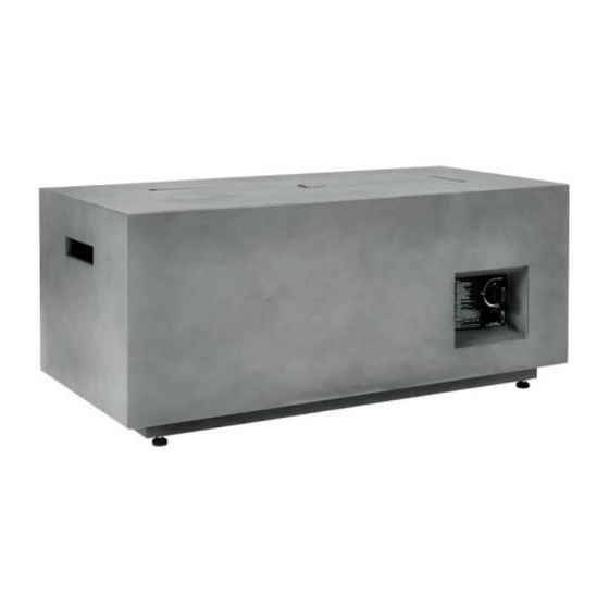
- Page 5 CONTENTS Item Description Lava Rocks 1 box Body Tank Holder Battery Control Knob (preassembled) Electronic Igniter (preassembled) Adjust Foot Protective Cover for Gas Cylinder...
- Page 6 ASSEMBLY INSTRUCTIONS 1.Turn over the body(C) and assemble 4pcs adjust feet(H) into bottom. 2. Check that the cont rol knob (F) for the gas supply system is tu rned to the “OFF” position before starting any assembly. 3. Put the 20 lb. p ropane gas tank (not included) into the tank holder (D).
- Page 7 4. Turn the cylinder valve on the tank clockwise to close the p ropane tank. PRESSURE Attach the p reassembled regulator RELIEF VALVE from the body (C) to the cylinder valve CYLINDER VALVE by turning the regulator coupling nut BLACK COUPLING NUT BLEED-OFF clockwise.
-
Page 8: Operation
OPERATION Before performing a leak test, be su re that no sparks can occur and you a re in a spacious outdoor area. Connect the propane gas tank to the regulator and turn the valve on the unit to the “o ff” position. -
Page 9: Maintenance
MAINTENANCE • Before performing any maintenance always disconnect propane gas tank. • Keep the heating item free and clear from combustible materials. • Visually inspect burner for obstructions and keep tank enclosure free and clear from debris. • Use a soft brush to get rid of the mild stains, loose dirt and soil after the burner and pumice stones/ lava rocks/LavaGlass™... -
Page 10: Troubleshooting
TROUBLESHOOTING Problem Cause Solution Igniter pin and burner are wet Dry off with a soft cloth Igniter battery is incorrectly inserted Check which direction the battery is inserted Igniter pin is broken Contact Bond Manufacturing for a Heating unit won’t light replacement part Electrode wire is loose or disconnected Reconnect wire to the igniter box located... - Page 11 CARE AND MAINTAINCE Service: Repair gas passages and associated components should be done only by a qualified service person. Caution: Always allow heater to cool before attempting service.
Need help?
Do you have a question about the GFHD42 and is the answer not in the manual?
Questions and answers