Table of Contents
Advertisement
Advertisement
Table of Contents

Related Manuals for Emerson MultiFlex ESR


Summary of Contents for Emerson MultiFlex ESR
- Page 1 026-1720 Rev 4 06-APR-2010 MultiFlex ESR Installation and Operation Manual...
- Page 3 Computer Process Controls, Inc. 1640 Airport Road Suite #104 Kennesaw, GA 31044 Phone 770-425-2724 Fax 770-425-9319 ALL RIGHTS RESERVED The information contained in this manual has been carefully checked and is believed to be accurate. However, Computer Process Controls, Inc. assumes no responsibility for any inaccuracies that may be contained herein.
-
Page 5: Table Of Contents
8.2.4. Main Select Screen.............................. 14 8.2.5. Valve Configuration Screens ..........................14 8.2.6. Network Screen ..............................14 VALVE SPECIFICATIONS TABLES ..........................15 ........................15 MERSON ONTROLS TEPPER ALVES ..........................15 PORLAN ARKER TEPPER ALVES MultiFlex ESR I&O Manual Table of Contents • v... -
Page 6: Introduction
For non-ECT Flow valves, the Multi- Flex ESR will only detect overcurrent situations Snap-Track Mounting and generate an alarm. (See Section 8.2.3., The MultiFlex ESR board fits into the standard Alarm Status Screens for details on alarm CPC 4" I/O board snap-track for mounting. descriptions.) -
Page 7: Multi Flex Esr Molex Connector Board (Discontinued )
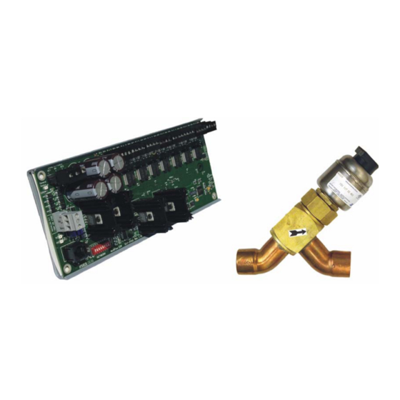
General Status LED Open LED (8) I/O Network Input TX and RX LEDs Close LED (8) Figure 1-2 - MultiFlex ESR Molex Connector Board Layout - 810-3198) Discontinued (P/N Installation The MultiFlex ESR control board is designed to be located in a central location, preferably near the valves it is driving. -
Page 8: Valve Wiring
150 feet. the eight screw terminal connectors along the top of the board (Figure 3-3) and matching the wire colors to the legend on the connectors. Use 3 • MultiFlex ESR I&O Manual 026-1720 Rev 4 06-APR-2010... -
Page 9: Setting The Terminating Resistance Jumpers
Setting the Network ing Resistance Jumpers Address and Baud Rate All MultiFlex ESR boards have a set of termi- Set the network address on the first five rockers nating resistance jumpers (one jumper for each of the dip switch (labeled S1) on the MultiFlex wire lead). -
Page 10: Software Overview
E2’s Standard Circuit applica- tion. As with previous ESR control, the valve tion. Once a valve on the MultiFlex ESR board may be configured to go to a fixed position, as has been associated with a Standard Circuit, the specified by the Temp Fail EEPR % parameter. -
Page 11: Programming E2 Version 2.21 And Above
A. Add Number of Boards By doing this, the associated Suction Group will A MultiFlex ESR board must be added to the E2 be able to float the suction setpoint to the highest in the same manner that an 8RO or a 16AI is possible value, while still maintaining the circuit added in the network setup of the controller. -
Page 12: Step 2: Add A Standard Circuit
Each standard circuit controls a single valve. In single circuit. this step, you must associate or "map" the valve on the MultiFlex ESR board to a particular cir- cuit. When a valve on the MultiFlex ESR board is associated with a circuit, the two are automati- 7 •... -
Page 13: Step 4: Set Up The Standard Circuit
To specify that the case circuit is going to be controlled by a valve on a MultiFlex ESR board, there are three important screens in the Standard Circuit application that you will need to alter. To edit a Standard Circuit application: ... - Page 14 This failsafe setting is always perature reaches setpoint. available. Table 6-1 - MultiFlex ESR Valve Parameters - E2 More Tab CommFailDefrost - If set to ENABLE (default), the scheduled defrost will occur if the board is in comm failure (offline). If set to DIS-...
-
Page 15: Step 5: Set Up The Multiflex Esr
Additional- ly, two configurable advisory parameters will appear. NOTE: Use the F1 and F2 keys to scroll Table 6-1 - MultiFlex ESR Valve Parameters - E2 More Tab between screens. 6.6. Step 5: Set Up the MultiFlex A. - Page 16 MultiFlex ESR. For each MultiFlex ESR point that has a valve attached to 11 • MultiFlex ESR I&O Manual 026-1720 Rev 4 06-APR-2010...
-
Page 17: Valve Zeroing
Step parameters for the valve, disconnect the NOTE: All alarms attempt to auto reset con- power plug from the MultiFlex ESR board, then tinuously every 10 minutes after the alarm was reconnect the power plug to reapply power to the first detected. -
Page 18: Screens
I/O Network. this valve type, this feature offers a high probability that if the valve becomes stuck, a Stuck Valve alarm • FAIL: USER CFG - The MultiFlex ESR board set- 13 • MultiFlex ESR I&O Manual 026-1720 Rev 4 06-APR-2010... -
Page 19: 8.2.4. Main Select Screen
The Option 2 screen will show the network set- changes to the settings. However, once the HHT tings for the MultiFlex ESR controller. There are is removed, the settings will go back to the val- no editable fields on this screen. This display is a ues programmed at the E2 if online. -
Page 20: Valve Specifications Tables
6386 1596 3193/6386 OverClose Total Watts Phase 75 ohms 75 ohms 72 ohms 75 ohms Resistance Hysteresis Motor Bipolar Bipolar Bipolar Bipolar ESR, CC100 ESR, CC100 CC100 ESR, CC100 products 15 • MultiFlex ESR I&O Manual 026-1720 Rev 4 06-APR-2010...
Need help?
Do you have a question about the MultiFlex ESR and is the answer not in the manual?
Questions and answers