Table of Contents
Advertisement
Quick Links
Installation
Operation
Maintenance
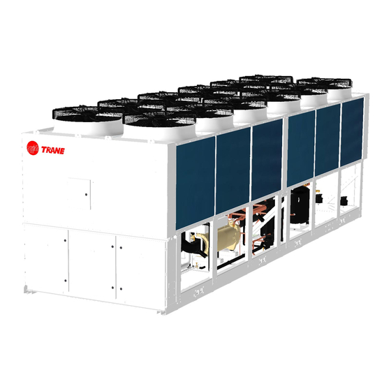
RTXC XE Air-to-Water Screw Heat Pump
SAFETY WARNING - Only qualified personnels should install and service the equipment. The installation, starting
up, and servicing of heating, ventilating, and air-conditioning equipment can be hazardous and requires specific
knowledge and training. Improperly installed, adjusted or altered equipment by an unqualified person could result
in death or serious injury. When working on the equipment, observe all precautions in the literature and on the
tags, stickers, and labels that are attached to the equipment.
April 2021
Original Instructions
1
572568050001
RTXC-SVX003B-EN
Advertisement
Table of Contents

Subscribe to Our Youtube Channel
Related Manuals for Trane RTXC XE Series


Summary of Contents for Trane RTXC XE Series
- Page 1 Installation Operation Maintenance RTXC XE Air-to-Water Screw Heat Pump 572568050001 SAFETY WARNING - Only qualified personnels should install and service the equipment. The installation, starting up, and servicing of heating, ventilating, and air-conditioning equipment can be hazardous and requires specific knowledge and training.
- Page 2 Important Responsible Refrigerant Practices! Trane believes that responsible refrigerant practices are important to the environment, our customers, and the air conditioning industry. All technicians who handle refrigerants must be certified. Know and follow the applicable laws for handling, reclaiming, recovering and recycling of certain refrigerants and the equipment used in these service procedures.
- Page 3 Installation Completion and Request for Trane Service Important: A copy of this completed form must be submitted to the Trane Service Agency that will be responsible for the start-up of the equipment. Start-up will NOT proceed unless applicable items listed in this form have been satisfactorily completed.
- Page 4 Minimum of two week advance notification is required to allow for scheduling of unit start-up. ADDITIONAL COMMENTS/INSTRUCTIONS Note: A copy of this completed form must be submitted to the Trane Service Agency that will be responsible for start-up of equipment.
-
Page 5: Table Of Contents
Contents Model Number Description ................6 General Information ..................7 General Data ....................10 Installation Requirements ................11 Electrical Controls .................... Controls ......................36 Operating Principles ..................38 Pre-Start Checkout ..................42 Unit Start-up and Shut-down Procedures ............46 Periodic Maintenance ..................49 Maintenance and Service ................ -
Page 6: Model Number Description
Model Number Description R T X C 1 1 2 3 4 5 10DXA01 CNNARN0D0N0N 6 7 8 9 10 11 12 13 14 15 16 17 18 19 20 21 22 23 24 Digit 1-4 Digit 5-7 Model: RTXC Air-cooled Screw Heat Pump Nominal Tonnage (Note: * indicate not available now) 110 = 110 tons *310 = 310 tons 160 = 160 tons... -
Page 7: General Information
General Information Warranty Warranty is based on the general terms and conditions of Trane.The warranty is void if the equipment is repaired or modified without the written approval of the manufacturer, if the operating limits are exceeded or if the control system or the electrical wiring is modified. Damage due to misuse, lack of maintenance or failure to comply with the manufacturer’s instructions or recommendations is not covered by the warranty obligation. - Page 8 At least every three months, attach a gauge and manually check the pressure in the refrigerant circuit to verify no refrigerant charge leakage. If the refrigerant leakage occurred, call a qualified service organization and the appropriate Trane sales office Note: Pressure will be approximately 200kPa gauge (29 psig) if shipped with a refrigerant “waiting charge”.
-
Page 9: General Data
General Data Cooling (1) Total cooling capacity Energy Efficiency Rating (EER) 3.33 3.47 3.33 3.33 3.28 Energy efficiency class (Eurovent) Space cooling efficiency qs,c SEER 4.46 4.68 4.67 4.55 4.55 Sound Power (2) dB(A) Sound Pressure (1m) dB(A) Water flow rate 17.8 27.9 30.6... -
Page 10: Installation Requirements
Installation Requirements Contractor Responsibilities Table 1 Contractor Responsibilities Trane Supplied Type of Trane Supplied Field Supplied Field Installed requirement Trane Installed Field Installed Foundation • Meet foundation requirements Rigging • Safety chains, Clevis connectors, Lifting beam • Neoprene Isolators Isolation... - Page 11 Table 2 for unit operating weights. Once in place, the unit must be level within 6 mm over its length and width. Trane is not responsible for equipment problems resulting from an improperly designed or constructed foundation. Figure 2 Foundation Diagram...
- Page 12 Fiqure 3- 1 Installation Clearance -RTXC110XE Fiqure 3- 2 Installation Clearance -RTXC160/180XE Fiqure 3- 3 Installation Clearance -RTXC200/220XE...
- Page 13 Note: In case of the height of enclosure around the unit higher than 1.5m, contact Trane local office. Figure 3- 4 Installation Clearance - Multi-Unit Figure 3 Acceptable Minimum Clearances NOTICE - No obstructions to outdoor fan airflow exit, including ductwork.
- Page 14 Rigging Refer to lifting instruction label on the unit, a specific lifting method is recommended as follow: The equipment should be moved by lifting. Do not use forklift truck to move or lift the unit. The cables, chains, slings and lifting beam crossbars must be provided by crane operator and attached on the lifting points.
- Page 15 Figure 4- 2 Rigging - RTXC160/180XE Figure 4- 3 Rigging - RTXC200/220XE Figure 4 RTXC XE Rigging...
- Page 16 Table 2 Unit lifting weights and center of gravity dimensions Opera Ckt1 Ckt2 Shippin g ting refrigera refrigera weight weight Model A (kg) C (kg) F (kg) G (kg) H (kg) nt charge( nt charge( (mm) (kg) (mm) (mm) (kg) (kg) (kg) (kg)
- Page 17 ISOLATOR CONTROL PANEL LOCATION Figure 5- 1 Isolator Placement - RTXC110XE CONTROL PANEL LOCATION Figure 5- 2 Isolator Placement - RTXC160/180XE Figure 5- 3 Isolator Placement - RTXC200/220XE Figure 5 Isolator Placement...
- Page 18 Table 3 Isolator Selection Neoprene Isolator Unit Model Quantity Maximum load weight per isolator (kg) Part Number RTXC110XE X10140305630 1361 RTXC160XE X10140305640 1814 RTXC180XE X10140305640 1814 RTXC200XE X10140305630 1361 RTXC220XE X10140305630 1361 RTXC310XE X10140305630 1361 RTXC330XE X10140305630 1361 X10140305640 1814 RTXC360XE X10140305630 1361...
- Page 19 Figure 7 Cover Plate Installation...
- Page 20 CAUTION - Water Strainer! To prevent evaporator damage, pipe strainers must be installed in the water supplies to protect components from water born debris. Trane is not responsible for equipment - only - damage caused by water born debris. CAUTION - Equipment Damage! Thoroughly flush all the water piping before making the final piping connections to the unit after external water piping installation and leakage test.
- Page 21 CAUTION - Equipment Damage! After water system clean and leakage test, fully drain the water from evaporator and piping system. Use pressurized air or nitrogen to blow out and ensure that no water stay in the evaporator and piping in winter. CAUTION - Equipment Damage! All inlet and outlet shutoff valves shown in Figure 8...
- Page 22 10. Flow switch contacts are closed on proof of water flow. • Wire flow switches in series with the water pump interlocks as in Trane wiring diagrams. Note: Dual flow switch for assembly unit RTXC310/330/360/400/440XE, install appropriate water flow switches at the water outlet of each unit, refer to Section of Master - slave unit.
- Page 23 Figure 10 Evaporator Water Pressure Drop Curves NOTICE - Water Flow Protection! The UC800 provides a 6-second time delay on the flow switch input before shutting down the unit on a Loss of flow diagnostic. Contact a qualified service organization if nuisance machine shutdowns persist.
- Page 24 It is recommended that the services of a qualified water treatment specialist be engaged to determine what water treatment, if any, is required. Trane assumes no responsibility for equipment failures which result from untreated or improperly treated water, or saline or brackish water.
- Page 25 electric bypass valve is required to be installed between the inlet and outlet pipes of each evaporator with the maximum bypass water flow rate through the valve at the fully open state no more than 40% of the unit rated water flow.
- Page 26 The use of untreated or improperly treated water could result in scaling, erosion, corrosion, algae or slime. It is recommended that the services of a qualified water treatment specialist be engaged to determine what water treatment, if any, is required. Trane assumes no responsibility for equipment failures which result from untreated or improperly treated water, or saline or brackish water.
- Page 27 that the BPHE can be isolated for service. A field installed safety or relief valve on the water side is required for the partial heat recovery to prevent risks resulting from a failure of the thermostat. Insulate water lines and other portions of the heat recovery water loop to prevent heat loss and potential injury due exposure to a hot surface.
-
Page 28: Electrical Controls
All wiring must comply with local codes. The installation (electrical) contractor must provide and install system Trane wiring diagrams. interlock wiring and power wiring. Specific electrical wiring diagrams are in CAUTION - Use Copper Conductors Only! Unit terminals are not designed to accept other types of conductors. - Page 29 Unit water pump control NOTICE - Equipment damage! Trane only allows the customer select either one of the offered schemes for chilled water pump control and evaporator antifreeze protection. Fail to do so may result in equipment damage and the loss of related guarantee rights without the authorization or approval from Trane.
- Page 30 Master-slave unit chilled water pump control For Master-Slave unit, the Master section and Slave section UC800 systems offer 2 relay contacts of chilled water pump control separately, total 2 control schemes are provided. Scheme 1, when the chilled water pump are corresponding with specific unit and controlled by this unit, the relay contact J2-4 and J2-6 of Master section module 1A20 controls the chilled water pump running and stop, when the unit receives the running command, this relay contact will close.
- Page 31 Events/States Description Alarm - Latching This output is true whenever there is any active diagnostic that requires a manual reset to clear, that affects the unit, or the Circuit. This classification does not include informational diagnostics. Alarm - Auto Reset This output is true whenever there is any active diagnostic that could automatically clear, that affects the unit, or the Circuit.
- Page 32 to return to normal operation. For Master Slave unit, no action is needed for the Slave section. Heating/Cooling Mode Setting The unit heating/cooling mode can be set by the “Setting” button of the display screen. UC800 also provides auxiliary control for a running mode. Connect a remote device contact to the J2-3 and J2-4 of module 1A19 can realize this function.
- Page 33 BACnet Communications Interface (BCI-C) UC800 provides an optional BACnet Communications Interface (BCI-C) between the unit and a Building Automation System (BAS). See Trane wiring diagrams for details. Master-Slave unit wiring connection (RTXC XE310/330/360/400/440 units) RTXC XE units have installed the modules of unit status. The Master-Slave unit operation is conducted by the wired connection among Unit Running/Stop Output module 1A26, External Auto/Stop module 1A14 and Heating/Cooling Mode Setting module 1A19.
-
Page 34: Controls
Controls Overview RTXC units utilize the following control/ interface components: • Tracer® UC800 Controller • Tracer® AdaptiView™ TD7 Operator Interface (Refer to RTXC Tracer® AdaptiView™ Operations Guide for details) UC800 Specifications Power Supply The UC800 receive 24 VDC (210 mA) power from the power supply located in the unit control panel. -
Page 35: Operating Principles
Operating Principles General The refrigeration cycle of RTXC XE is conceptually similar to that of other Trane air-cooled screw heat pumps, including single refrigerant circuit unit, dual refrigerant circuit unit, and assembly unit with master- slave control system. RTXC110XE has a single refrigerant circuit with one compressor with economizer and one water loop. - Page 36 (Economizer Only for RTXC110/180/220XE) Refrigerant NOTICE - Equipment damage! Use only refrigerants specified on the unit nameplate and Trane OIL00317. Failure to do so may cause compressor damage and improper unit operation. Compressor The compressor is of cast iron, semi-hermetic construction, twin screw type. Each compressor has two rotors - “male”...
- Page 37 Water side heat exchanger RTXC XE uses a falling film evaporator to exchange heat of refrigerant in the shell side with water flow in tubes. In cooling mode, liquid refrigerant evenly drop on the external surface of tube bundle and exchange heat with water flow in tube, specified liquid level in falling film maintained by expansion valve to ensure high efficiency of the heat exchange, vapored refrigerant exit through the suction line, excessive refrigerant and oil left at the bottom of falling film through oil return valve back to compressor.
- Page 38 bearing then return to suction port of rotors through internal oil channel of compressor shell. All the two oil flow mixed with refrigerant gas through rotors discharge back to oil separator. In cooling mode, the minority oil accumulated in refrigerant liquid of evaporator go back to the bottom cavity of compressor through oil return solenoid valve of oil return pipe;...
- Page 39 ______ Entering air temperature Heating mode: Water side heat exchanger (condenser) Min temperature (°C) Max temperature (°C) Entering water temperature (startup) Leaving water temperature (running) Air side heat exchanger (evaporator) Min temperature (°C) Max temperature (°C) Entering air temperature Partial Heat Recovery mode: Water side heat exchanger (evaporator) Min temperature (°C) Max temperature (°C)
-
Page 40: Pre-Start Checkout
Pre-Start Checkout Prestart procedures WARNING - Hazardous Voltage! Disconnect all electric power, including remote disconnects before servicing. Follow proper lockout/tagout procedures to ensure the power can not be inadvertently energized. Failure to disconnect power before servicing could result in death or serious injury. When installation is complete, but prior to putting the unit into service, the following prestart procedures must be reviewed and verified correct. - Page 41 It is recommended that the services of a qualified water treatment specialist be engaged to determine what water treatment, if any, is required. Trane assumes no responsibility for equipment failures which result from untreated or improperly treated water or saline or brackish water.
- Page 42 Ensure that the oil sump heaters have been operating for a minimum of 12 hours before first startup after long time shutdown. Failure to do so may result in compressor damage. 14. Check the oil level of oil separator sump if desired. Note: Never to operate the compressor during oil level check.
- Page 43 Do not interchange any load leads that are from the unit contactors or the motor terminals. The terminal connection of the compressor after maintenance must be consistent with Trane wiring diagrams. Do not interchange any load leads that are from the unit contactors or the motor terminals to prevent compressor from damage in a reverse rotation.
-
Page 44: Unit Start-Up And Shut-Down Procedures
Important: Initial unit commissioning start-up must be performed by Trane or an agent of Trane specifically authorized to perform start-up and warranty of Trane products. Contractor shall provide Trane (or an agent of Trane specifically authorized to perform start-up) with notice of the scheduled start-up at least two weeks prior to scheduled start-up. - Page 45 - Leaving water temperature NOTICE - Equipment Damage! Use only refrigerants specified on the unit nameplate and Trane OIL00317. Failure to do so may cause compressor damage and improper unit operation. CAUTION - Personal injury! Avoid breathing refrigerant vapour and any contact with liquid or gas.
- Page 46 Extended Unit Shutdown The following procedure is to be followed if the system is to be taken out of service for an extended period of time (i.e. seasonal shutdown): Perform the normal unit stop sequence using the Stop key. Open the electrical disconnect switches for the unit. Lock the switches in the “OPEN” position. Remove evaporator power before draining evaporator to avoid heater burnout.
-
Page 47: Periodic Maintenance
9. If unit measurements vary significantly from values listed in the table, problems may exist with refrigerant charge levels. Contact your local Trane Service Agency. Observe and clean the air side fin-tube heat exchanger if blocked. Record the water pressure drop across the evaporator. Clean water strainer if necessary. - Page 48 Clean and repaint any areas that show signs of corrosion. Inspect all piping components for leakage and/or damage. Clean all water strainers. Inspect the air side heat exchanger. Clean if necessary. Inspect the evaporator tubes for fouling. Clean if necessary. Clean the condenser fans.
-
Page 49: Maintenance And Service
Power Supply Unit Status (before Start-up) Voltage (V): Chiller appearance at arrival: Frequency (Hz): Pressure from TD7 (bar): ckt1: ckt2: Phase Imbalance Rate (%): R134a Charge (kg): ckt1: ckt2: Compressor Data Serial #: Serial #: Model #: Model #: Compressor Compressor Series #: Series #:... - Page 50 Close the service valve and remove the hose. NOTICE - Insufficient Subcooling! Proper subcooling can be determined by operator log, service technician experience or consulting Trane local service. NOTICE - Gas Refrigerant Adding! Add gas refrigerant only during operation to avoid compressor failure.
- Page 51 Use only Trane OIL00317. Failure to do so may cause compressor damage and improper unit operation. Trane Polyolester Oil is the approved oil for the RTXC XE units. Polyolester oil is extremely hygroscopic meaning it readily attracts moisture. The oil can not be stored in plastic containers due to the hygroscopic properties.
- Page 52 To clean the coils use a soft brush and a sprayer such as a garden pump type or a high-pressure type. A high quality detergent such as Trane Coil Cleaner (Part No. CHM-00255) is recommended. See RTAC- SVG01B-EN for maintenance and cleaning procedures.
- Page 53 of the selected lift connection device must meet or exceed the published weight of the waterbox. Insure the lift connection device has the correct connection for the waterbox. Remove waterbox bolts and lift the waterbox away from the shell. WARNING - Heavy Objects! Failure to properly lift waterbox could result in death or serious injury.
- Page 54 Table 8 Main components weights (kg) Air side heat exchanger Water box Water side heat Reversing Control panel Model Compressor Oil separator Receiver exchanger assembly valve Inlet water Return Vertical Slab side water side RTXC 110XE RTXC 160XE RTXC 180XE RTXC 200XE 1003 RTXC 220XE...
- Page 55 Other technical documentation e.g. quality assurance measures for design and production Name and address of the person (established in the Community) complied the technical files: SOCIETE TRANE 1 rue des Ameriques F 88190 GOLBEY Responsible for making this declaration is the: Manufacturer □...
- Page 56 Trane - by Trane Technologies (NYSE: TT), a global innovator - creates comfortable, energy efficient indoor environments for commercial and residential applications. For more information, please visit trane.com or tranetechnologies.com. Trane has a policy of continuous product and product data improvements and reserves the right to change design and specifications without notice.
Need help?
Do you have a question about the RTXC XE Series and is the answer not in the manual?
Questions and answers
which is th maximal weight par isolator, is there any marge? I need more than 1814 kg for an HSE 180. is it possible to have an isolator more resistent?