Table of Contents
Advertisement
INSTALLATION INSTRUCTIONS
Multi-Position Cased Coils with Leak Mitigation Kit
Cooling and Heat Pump Compatible
Factory Installed R454B Refrigerant Leakage Sensor
Please read this manual carefully and keep it for future reference.
All the pictures in this manual are for illustrations purpose only.
18-AD49D1-1A-EN
Advertisement
Table of Contents

Related Manuals for Trane 5MXCA003AC6HCA


Summary of Contents for Trane 5MXCA003AC6HCA
- Page 1 INSTALLATION INSTRUCTIONS Multi-Position Cased Coils with Leak Mitigation Kit Cooling and Heat Pump Compatible Factory Installed R454B Refrigerant Leakage Sensor Please read this manual carefully and keep it for future reference. All the pictures in this manual are for illustrations purpose only. 18-AD49D1-1A-EN...
-
Page 2: Table Of Contents
RECOGNIZE THIS SYMBOL AS AN INDICATION OF IMPORTANT SAFETY INFORMATION WARNING These instructions are intended as an aid to qualified licensed service personnel for proper installation, adjustment and operation of this unit. Read these instructions thoroughly before attempting installation or operation. Failure to follow these instruction may result in improper installation, adjustment, service or maintenance, which could possibly lead to fire, electrical shock, property damage, personal injury or even death. -
Page 3: Safety
This document is customer property and is to remain with this unit. These instructions do not cover all the different variations, nor do they provide for every possible contingency to be met in connection with installation. All phases of this installation must comply with national state and local codes. If additional information is required, please contact your local distributor. -
Page 4: Safety Precautions
1.2 Safety Precautions WARNING DANGER PROPOSITION 65: This appliance contains fiberglass insulation. Respirable particles of fiberglass are known to the State of California to Disconnect all power to unit before installing or cause cancer. servicing. More than one disconnect switch may be required to de-energize the equipment. - Page 5 WARNING WARNING WARNING Only use this unit in a well-ventilated area and When repairing the refrigerating system, comply ensure unit's airflow inlet and outlet would not be with the following precautions prior to conducting impeded by obstructions. Do not use this unit in work on the system: the following locations: –...
- Page 6 Leak detection fluids are also suitable for use Refrigerant pipe or components are installed in a with most refrigerants but the use of detergents position where they are unlikely to be exposed to containing chlorine shall be avoided as the any substances which may corrode refrigerant chlorine may react with the refrigerant and containing components, unless the components...
- Page 7 Prior to recharging the system, it shall be When transferring refrigerant into cylinders, pressure-tested with the appropriate purging ensure that only appropriate refrigerant recovery gas. The system shall be leak-tested on cylinders are employed. Ensure that the correct completion charging prior number of cylinders for holding the total system commissioning.
- Page 8 The effectiveness of signs should not be When the system is installed and operated in a diminished by too many signs being placed small room, it is required to maintain the together. concentration of the refrigerant below the limit, in case a leak occurs.
-
Page 9: About The Product
2 ABOUT THE PRODUCT The coil can be positioned for bottom return air in the upflow and horizontal right applications. It must be positioned for top return when in downflow and horizontal left applications. See figure 2-1. For furnace applications, the coil must be installed downstream (in the air outlet) of the furnace NOTE This coil comes with a factory-installed heat shield on the drain pan. -
Page 10: Codes & Regulations
WEIGHT SUPPLY MODELS UNIT HEIGHT UNIT WIDTH LIQUID LINE/ DUCT "A" (lb [kg]) "H" (in [mm]) "W" (in [mm]) VAPOR LINE (in [mm]) 5MXCA003AC6HCA 20"[508] 14-1/2"[368] 13"[330] 3/8" / 3/4" 44[20] 5MXCB004AC6HCA 20"[508] 17-1/2"[445] 16"[407] 3/8" / 3/4" 46[21] 5MXCC005AC6HCA 20"[508]... -
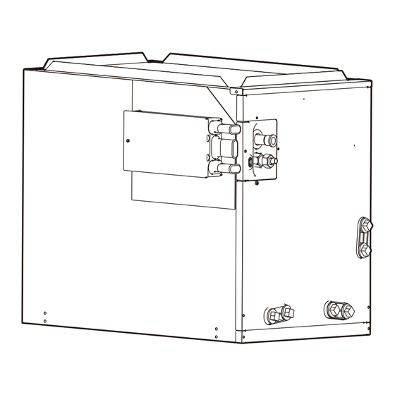
Page 11: Refrigerant Sensor
3 INSTALLATION 2.5 Refrigerant Sensor 3.1 Replacement Parts R454B refrigerant leakage sensor is pre-configured on the coil from the factory. It is located in the bottom right Contact your distributor for authorized replacement corner of the coil to meet different installation scenarios. parts. -
Page 12: Installation And Trap Connection
3.3 Installation and Trap Connection 1. See Fig. 3-1 for coil installation and drain connection. 2. Installation notes: A. Shut off or disconnect gas furnace's power and remove gas pipe if necessary. B. Disconnect and remove a sufficient portion of the supply ductwork to provide clearance for the cased coil. C. -
Page 13: Installation Of Refrigerant Sensor
Fig. 3-2 Transition for horizontal left orientation 3. If the coil is used in connection with an upflow furnace in horizontal left orientation, a sheet metal transition can be installed between the furnace supply air outlet and the evaporator coil supply air inlet to create clearance between coil lineset and furnace flue outlet for A-cabinet non-condensing furnaces and for all cabinet size condensing furnaces. -
Page 14: Refrigerant Charge And Room Area Limitations
3.5 Refrigerant Charge and Room Units mounted higher than 70-55/64 inches and spaces divided by partition walls that are no higher than Area Limitations 62-63/64 inches shall be considered a single space. Rooms on the same floor and connected by an open In UL/CSA 60335-2-40, R454B refrigerant is classified passageway between the spaces can be considered a as class A2L, which is mildly flammable. - Page 15 3.5.2. The allowed maximum refrigerant The minimum opening for natural ventilation (Anvmin) in connected rooms is related to the room area (A), the charge and required minimum room actual refrigerant charge of refrigerant in the system (Mc), area and the allowable MAXIMUM REFRIGERANT CHARGE in the system (Mmax), Anvmin can be determined according to Table 3-1.
- Page 16 CAUTION The minimum circulation airflow Qmin Qmin The allowable maximum refrigerant charge of lb-oz lb-oz the Table 3-2 or the required minimum room area of the Table 3-3 is available only if the 10-2 following conditions are met: 10-9 Minimum velocity of 3.28 ft/s, which is calculated 11-0 as the indoor unit airflow divided by the nominal face area of the outlet.
-
Page 17: Installation Of The R454B Leak Mitigation Kit
Installation scheme flow chart When working with or around hazardous chemicals, ALWAYS refer to the appropriate Check if the minimum room SDS and OSHA/GHS (Global Harmonized area meets the requirements System of Classification and Labelling of Chemicals) guidelines for information on allowable personal exposure levels, proper respiratory protection... - Page 18 Minimum Airflow Setting (5) In the side installation, if the drill is used during System refngerant charge Minimum Airflow Setting installation, the drilling depth should not exceed (lb) ♦ (CFM) 0.2 inches to prevent the glass fiber cotton from less than 4 no mimimum being hit;...
- Page 19 Fig. 3-8 Install left view Fig. 3-9 Wall installation view WARNING If the installation configuration does not allow for the kit to be mounted on the cased coil, the leak mitigation kit can be installed on a nearby wall or surface as shown in Fig.
- Page 20 3.6.1.4 Refrigerant sensor connection Connect the cable of refrigerant sensor to CN26 on the board in MCB kit. CN26 WARNING The refrigerant sensor must be in the original position and cannot be changed. R454B REFRIGERANT SENSOR WARNING After installing the sensor, add a zip tie to strain relief the incoming refrigerant sensor wire.
- Page 21 A2L detection sensor RS485 communication port THERMOSTAT RS485 FURNACE THERMOSTAT Leak Mitigation Kit Outdoor Unit connection 3.6.2.2 Alarm wiring WARNING Alarm output Tightening the rubber ring after wiring for insect CN34 wires protection. Central monitor WARNING The rated operating condition of ALARM is 24 V AC/1 A or 30 V DC/1A or 250 V AC/1 A. The type of wiring for ext output should use cables of AWG 18 (Min.
-
Page 22: Pistion/Txv Installation
Mitigation Board Accessory Shutdown and Alarm Switch Power Source CN34 Switch 24 V Coil RELAY ALARM 24 V FURNACE Rated @ 1 amp 24 V AC / 120 V AC / 240 V AC 4 PISTION/TXV INSTALLATION 4.1 Piston Installation 1. -
Page 23: Optional Txv Kit Installation
4.2 Optional TXV Kit Installation Outdoor Unit TXV kit part numbers Capacity (Tons) Reference TXV kit literature for installation instructions. 5AYTXVH3A1836A 5AYTXVH3A1836A 1.Use a wrench to loosen the nut and remove the sealing flange and sealing gasket. 5AYTXVH3A1836A 2.Take out the connecting pipe from accessory package 5AYTXVH3A1836A and braze the connecting pipe onto the refrigeration-out 5AYTXVH3A4248A... -
Page 24: Refrigerant Line
5 REFRIGERANT LINE — Mechanical joints in compliance with ISO 14903 or UL 207 (U.S. only). The suction pipe and liquid pipe of the indoor unit need to — Welded or brazed joints. be protected and cannot be grabbed when moving the —... -
Page 25: Ductwork
6 DUCTWORK WARNING If appliances connected via an air duct system to Field ductwork must comply with the National Fire one or more rooms are installed in a room with an Protection Association NFPA 90A, NFPA 90B and any area less than shown in section 3.5 Table 3-3, applicable local ordinance. -
Page 26: Airflow Performance
7 AIRFLOW PERFORMANCE Airflow performance [CFM VS Pressure drop] Pressure drop characteristics for cooling and heat pump coils Pressure drop (Inches of water) 0.15 0.25 0.35 0.4* Model 0.05 1063 5MXCA003AC6HCA 1024 1122 1217 5MXCB004AC6HCA 1102 1259 1398 1530 1651 5MXCC005AC6HCA... -
Page 27: Drain Application
8 DRAIN APPLICATION to protect plastic drain pan, complete the drain line installation (Fig. 8-1). Use (Fig. 8-2) as a template for typical drain pipe routing. 8.1 Condensate Drain Piping This figure shows how to avoid interference with vent piping. Consult local codes for special requirements. - Page 28 About Trane and American Standard Heating and Air Conditioning For more information, please visit www.trane.com or www.americanstandardair.com committed to using environmentally conscious print practices. 18-AD49D1-1A-EN 09 Sep 2024 ©2024 Supersedes (new)
Need help?
Do you have a question about the 5MXCA003AC6HCA and is the answer not in the manual?
Questions and answers