Table of Contents
Advertisement
Quick Links
®
INSTALLATION INSTRUCTIONS
Wide-Band Exhaust Gas Oxygen
Sensor Interface
ST994 / ST996
CAUTION: CAREFULLY READ INSTRUCTIONS BEFORE PROCEEDING
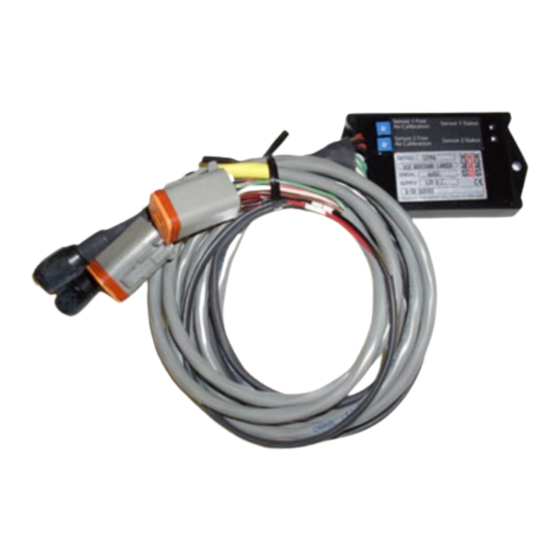
OVERVIEW
The Control Unit is a dual channel air/fuel ratio
(AFR) metering system designed to be used with an exist-
ing data acquisition system. The system has two 0-5 volt
analog AFR outputs. The compact size and wide supply
voltage range also allow operation from small rechargeable
batteries in a broad range of applications.
By utilizing miniature surface mount electronics
technology, digital signal processing techniques, and a
switching power supply for the sensor heater, the Control
Unit provides the same level of accuracy as lab systems
costing much more.
REPLACEMENT SENSORS AND
ACCESSORIES
We offer replacement sensors with Deutsch
connector installed: ST269552.
If you plan to terminate your own sensors, use the
following color chart:
Terminal
1
2
3
4
5
6
Wire Color
Red
Black
Yellow
White
Gray
Seal
INSTALLATION
1. Turn off the ignition switch and disconnect the battery
ground cable before proceeding.
2. The Bosch LSU 4.2 sensors should be located on the
header pipe about 6-8 inches from the head flange.
Ideally the sensor tip should face down to avoid accu-
mulation of condensation. When choosing a mounting
location, allow several inches clearance for the sensor
wire harness. The wire harness must exit straight out
from the sensor. Do not loop the harness back onto the
sensor body.
3. 18 x 1.5 mm weld nuts must be welded onto the ex-
haust pipe. After welding, run an 18 x 1.5 mm tap
through the threads. Failure to clean the threads may
result in sensor damage. Note that most automotive
muffler shops are familiar with oxygen sensor weld nut
installation on custom pipes. Do not install the sensors
until after the free air calibration procedure described in
Figure 1 – Control Unit
Advertisement
Table of Contents

Related Manuals for Stack ST994


Summary of Contents for Stack ST994
- Page 1 ® INSTALLATION INSTRUCTIONS Wide-Band Exhaust Gas Oxygen Sensor Interface ST994 / ST996 CAUTION: CAREFULLY READ INSTRUCTIONS BEFORE PROCEEDING OVERVIEW INSTALLATION 1. Turn off the ignition switch and disconnect the battery The Control Unit is a dual channel air/fuel ratio ground cable before proceeding.
- Page 2 Figure 2 - Controller Hookup 0-5V OUTPUT SCALED AFR = 10 + (2 x VOLT) TO SWITCHED SENSOR 1 CABLE +12V POWER IDENTIFIED BY YELLOW BAND SENSOR 1 AFR SENSOR 1 INPUT SENSOR OUTPUT INPUT DATA ACQUISITION SYSTEM SENSOR 2 AFR SENSOR 2 INPUT SENSOR...
- Page 3 SENSOR LIFE AND CALIBRATION pressure causes exaggerated AFR indications under rich and lean conditions, but has little effect at 14.7 AFR When used in a racing application with leaded (stoichiometric). Race vehicle exhaust systems are free petrol, sensor life will probably be less than 10 hours. flowing and problems with exhaust back pressure are not Free air calibration should be performed on a regular likely.
- Page 4 WARRANTY Stack Limited warrants this product (excepting associated sensors which are consumable items - there is no warranty on sensors.) to be free from defects caused by faulty materials or poor workmanship for 1 year from the date of consumer purchase. This warranty applies only to the original purchaser of product and is non-transferable.
Need help?
Do you have a question about the ST994 and is the answer not in the manual?
Questions and answers