KROHNE OPTISOUND 3020 C Handbook
Ultrasonic level transmitter
Hide thumbs
Also See for OPTISOUND 3020 C:
Table of Contents
Advertisement
Quick Links
Advertisement
Table of Contents

Related Manuals for KROHNE OPTISOUND 3020 C


Summary of Contents for KROHNE OPTISOUND 3020 C
- Page 1 OPTISOUND 3020 C Handbook Ultrasonic Level Transmitter Foundation Fieldbus...
-
Page 2: Table Of Contents
How to proceed if a repair is necessary ................40 Dismount..........................41 Dismounting steps......................41 Disposal ......................... 41 Supplement ..........................42 Technical data ........................ 42 Device communication Foundation Fieldbus ..............45 Dimensions ........................49 Trademark ........................51 OPTISOUND 3020 C • Foundation Fieldbus... - Page 3 Contents Safety instructions for Ex areas Take note of the Ex specific safety instructions for Ex applications. These instructions are attached as documents to each instrument with Ex approval and are part of the operating instructions. Editing status: 2019-03-12 OPTISOUND 3020 C • Foundation Fieldbus...
-
Page 4: About This Document
The dot set in front indicates a list with no implied sequence. Sequence of actions Numbers set in front indicate successive steps in a procedure. Battery disposal This symbol indicates special information about the disposal of bat- teries and accumulators. OPTISOUND 3020 C • Foundation Fieldbus... -
Page 5: For Your Safety
During work on and with the device, the required personal protective equipment must always be worn. Appropriate use OPTISOUND 3020 C is a sensor for continuous level measurement. You can find detailed information about the area of application in chapter " Product description". Operational reliability is ensured only if the instrument is properly used according to the specifications in the operating instructions manual as well as possible supplementary instructions. -
Page 6: Eu Conformity
English language. Installations in the US shall comply with the relevant requirements of the National Electrical Code (ANSI/NFPA 70). Installations in Canada shall comply with the relevant requirements of the Canadian Electrical Code. OPTISOUND 3020 C • Foundation Fieldbus... -
Page 7: Product Description
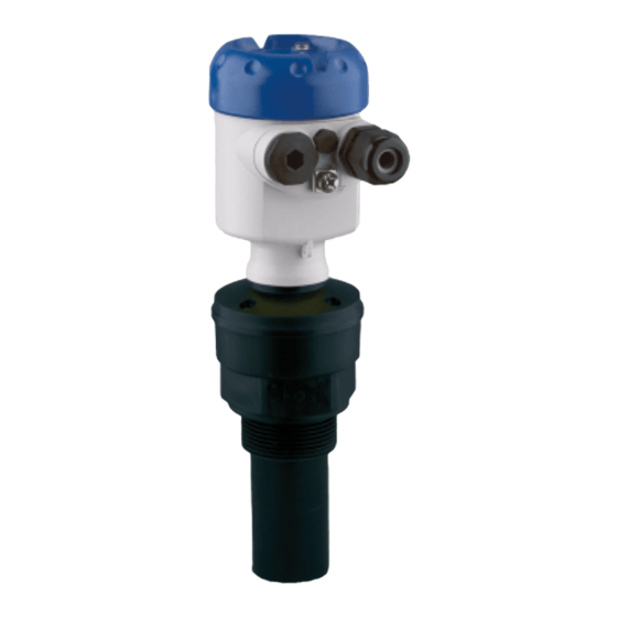
Housing with electronics • Housing lid with integrated display and adjustment module (optional) The components are available in different versions. Fig. 1: OPTISOUND 3020 C, version with plastic housing Housing lid with integrated display and adjustment module (optional) Housing with electronics 3 Process fitting with transducer Type label The type label contains the most important data for identification and use of the instrument: •... -
Page 8: Principle Of Operation
Technical data: For example approvals, process temperature, process fitting/material, signal output, voltage supply, protection Principle of operation Application area OPTISOUND 3020 C is an ultrasonic sensor for continuous level measurement. It is suitable for liquids and solids in virtually all indus- tries, particularly in the water and waste water industry. Functional principle The transducer of the ultrasonic sensor transmits short ultrasonic pulses to the measured product. These pulses are reflected by... - Page 9 • Storage and transport Storage and transport temperature see chapter " Supplement - temperature Technical data - Ambient conditions" • Relative humidity 20 … 85 % Lifting and carrying With instrument weights of more than 18 kg (39.68 lbs) suitable and approved equipment must be used for lifting and carrying. OPTISOUND 3020 C • Foundation Fieldbus...
-
Page 10: Mounting
Prior to setup you have to replace these protective caps with ap- proved cable glands or close the openings with suitable blind plugs. The reference plane for the measuring range is the lower edge of the Reference plane for measuring range transducer. Make sure that a minimum distance from the reference plane - the so-called dead zone, in which measurement is not possible - is OPTISOUND 3020 C • Foundation Fieldbus... - Page 11 100% Fig. 4: Measuring range (operating range) and max. measuring distance full empty (max. measuring distance) Measuring range Pressure/Vacuum Gauge pressure in the vessel does not influence OPTISOUND 3020 C. Low pressure or vacuum does, however, damp the ultrasonic pulses. This influences the measuring result, particularly if the level is very low. With pressures under -0.2 bar (-20 kPa) you should use a different measuring principle, e.g. radar or guided radar (TDR). OPTISOUND 3020 C • Foundation Fieldbus...
-
Page 12: Mounting Instructions
4 Mounting Mounting instructions Screwing in Screw OPTISOUND 3020 C into the mounting socket with an ap- propriate spanner applied to the hexagon of the process fitting. Max. torque see chapter "Technical data". Warning: The housing must not be used to screw the instrument in! Applying tightening force can damage internal parts of the housing. - Page 13 Fig. 7: Recommended socket mounting If the reflective properties of the medium are good, you can mount OPTISOUND 3020 C on sockets which are higher than the length of the transducer. You will find recommended values for socket heights in the following illustration. The socket end should be smooth and burr- free, if possible also rounded. Carry out a false signal suppression.
- Page 14 "clear view" to the measured product. In case of existing vessel installations, a false signal suppression should be carried out during setup. OPTISOUND 3020 C • Foundation Fieldbus...
- Page 15 Fig. 11: Cover flat, large-area profiles with deflectors Agitators If there are agitators in the vessel, a false signal suppression should be carried out with the agitators in motion. This ensures that the interfering reflections from the agitators are saved with the blades in different positions. Fig. 12: Agitators Do not mount the instruments in or above the filling stream. Make sure Inflowing medium that you detect the product surface, not the inflowing product. OPTISOUND 3020 C • Foundation Fieldbus...
- Page 16 Standpipe measurement By using a standpipe (surge or bypass tube), the influence of vessel installations, foam generation and turbulence is excluded. Standpipes must extend all the way down to the requested min. level, as measurement is only possible within the tube. OPTISOUND 3020 C • Foundation Fieldbus...
- Page 17 Fig. 14: Standpipe in the tank Vent hole: ø 5 … 10 mm (0.197 … 0.394 in) OPTISOUND 3020 C can be used from tube diameters of 50 mm (1.969 in). Avoid large gaps and thick welding joints when connecting the tubes.
- Page 18 90° Fig. 16: Flow measurement with Khafagi-Venturi flume: d = Min. distance to sen- sor; h = max. filling of the flume; B = tightest constriction in the flume max. Position sensor 2 Venturi flume In general, the following points must be observed: • Installation of the sensor at the inlet side • Installation in the centre of the flume and vertical to the liquid surface • Distance to the Venturi flume • Min. distance of the sensor to max. storage level OPTISOUND 3020 C • Foundation Fieldbus...
-
Page 19: Connecting To Power Supply
The cable screens to the power supply unit and to the next distributor must be connected to each other and also connected to ground potential via a ceramic capacitor (e.g. 1 nF, 1500 V). The low frequency potential equalisation currents are thus suppressed, OPTISOUND 3020 C • Foundation Fieldbus... -
Page 20: Connection Procedure
Fig. 17: Connection steps 6 and 7 8. Press down the opening levers of the terminals, you will hear the terminal spring closing 9. Check the hold of the wires in the terminals by lightly pulling on them OPTISOUND 3020 C • Foundation Fieldbus... -
Page 21: Wiring Plan, Single Chamber Housing
Fig. 19: Electronics and connection compartment - single chamber housing Spring-loaded terminals for Foundation Fieldbus connection Simulation switch ("on" = simulation mode) Spring contacts for display and adjustment module Interface for service Ground terminal for connection of the cable screening OPTISOUND 3020 C • Foundation Fieldbus... -
Page 22: Wiring Plan, Double Chamber Housing
The following illustrations apply to the non-Ex as well as to the Ex-ia version. Housing overview Fig. 21: Double chamber housing Housing cover - connection compartment Blind plug Housing cover - electronics compartment Filter element for air pressure compensation Cable gland OPTISOUND 3020 C • Foundation Fieldbus... - Page 23 Ground terminal for connection of the cable screening Connection compartment I 2 C Fig. 23: Connection compartment, double chamber housing Spring-loaded terminals for voltage supply Plug connector for service interface Ground terminal for connection of the cable screening OPTISOUND 3020 C • Foundation Fieldbus...
-
Page 24: Switch-On Phase
Fig. 24: Wiring plan - double chamber housing Voltage supply, signal output Switch-on phase Switch-on phase After OPTISOUND 3020 C is connected to voltage supply or after voltage recurrence, the instrument carries out a self-check for approx. 30 seconds. The following steps are carried out: •... -
Page 25: Set Up With The Display And Adjustment Module
Fig. 25: Insert display and adjustment module in the single chamber housing Note: If you intend to retrofit the instrument with a display and adjustment module for continuous measured value indication, a higher lid with an inspection glass is required. OPTISOUND 3020 C • Foundation Fieldbus... -
Page 26: Adjustment System
5 s, the display returns to the main menu. The menu language is then switched over to " English". Approx. 60 minutes after the last pressing of a key, an automatic reset to measured value indication is triggered. Any values not confirmed with [OK] will not be saved. OPTISOUND 3020 C • Foundation Fieldbus... -
Page 27: Setup Steps
[OK]. ▶ Basic adjustment Display Diagnostics Service Info 2. Select the menu item "Basic adjustment" with [->] and confirm with [OK]. Now the menu item "Min. adjustment" is displayed. Min. adjustment 0.00 % 5.000 m(d) 4.000 m(d) OPTISOUND 3020 C • Foundation Fieldbus... - Page 28 To adapt the sensor to these measuring conditions, this menu item offers different options depending on whether liquid or bulk solid is selected. With "Liquids" these are "Storage tank", "Stilling tube", "Open vessel" or "Stirred vessel", with "Solid", "Silo" or "Bunker". OPTISOUND 3020 C • Foundation Fieldbus...
- Page 29 [->] key. Menu section, display Display - Indicated value Radar, guided microwave and ultrasonic sensors deliver the following measured values: • SV1 (Secondary Value 1): Percentage value after the adjustment • SV2 (Secondary Value 2): Distance value before the adjustment • PV (Primary Value): Linearised percentage value • AI FB1 (Out) In the menu item "Display" you can define which value should be indicated on the display. OPTISOUND 3020 C • Foundation Fieldbus...
- Page 30 Measurement reliability Sensor status Diagnosis - Curve selec- With ultrasonic sensors, the "Echo curve" represents the signal tion strength of the echoes over the measuring range. The unit of signal OPTISOUND 3020 C • Foundation Fieldbus...
- Page 31 A false echo memory OPTISOUND 3020 C • Foundation Fieldbus...
- Page 32 The level would then no longer be detectable in this area. Service - Extended set- The menu item "Extended setting" offers the possibility to optimise ting OPTISOUND 3020 C for applications in which the level changes very quickly. To do this, select the function "Quick level change > 1 m/min.". Extended setting quick level change > 1 m/min.
- Page 33 Like basic adjustment, but in addition, special parameters are reset to default values. Sensor-specific basic adjustment. Depending on the sensor type, see chapter "Technical data". Depending on the sensor type, see chapter "Technical data". Special parameters are parameters which are set customer-specifically on the service level with the adjustment software PACTware. OPTISOUND 3020 C • Foundation Fieldbus...
- Page 34 Vessel form • Damping • Linearisation curve • Sensor-TAG • Displayed value • Unit of measurement • Language The following safety-relevant data are not read out or written: • Copy sensor data Copy sensor data? OPTISOUND 3020 C • Foundation Fieldbus...
- Page 35 PC Last change using PC • Device-ID • Sensor-TAG Device ID < max. 32 characters > Sensor-TAG (PD_TAG) < max. 32 characters > • Sensor details, e.g. approval, process fitting, seal, measuring cell, measuring range, electronics, housing, cable entry, plug, cable length etc. OPTISOUND 3020 C • Foundation Fieldbus...
-
Page 36: Menu Schematic
Medium Vessel shape 000.0 % 100.0 % Liquid Storage tank 10.000 m(d) 0.000 m(d) 1.245 m(d) 6.789 m(d) Damping Linearisation curve Linear Display Basic adjustment ▶ Display Diagnostics Service Info Displayed value Backlight ► AI-Out Switched off OPTISOUND 3020 C • Foundation Fieldbus... - Page 37 Date of manufacture Last change using PC < max. 32 characters > OPTISOUND 30x0 C 24. March 2015 Sensor-TAG (PD_TAG) Serial number Software version 10. April 2015 < max. 32 characters > 12345678 3.80 Sensor characteristics Display now? OPTISOUND 3020 C • Foundation Fieldbus...
-
Page 38: Saving The Parameterisation Data
The data remain permanently stored there even if the sensor supply fails. The proce- dure is described in menu item " Copy sensor data". OPTISOUND 3020 C • Foundation Fieldbus... -
Page 39: Maintenance And Fault Rectification
Incorrect termination Check termination at the beginning and end points of the bus and terminate, if necessary, according to the specification Instrument not connected Check and correct, if necessary to the segment OPTISOUND 3020 C • Foundation Fieldbus... -
Page 40: Exchanging The Electronics Module
If there is no electronics module available on site, one can be ordered from the Krohne agency serving you. How to proceed if a repair is necessary If it is necessary to repair the instrument, please contact the responsi- ble Krohne agency. OPTISOUND 3020 C • Foundation Fieldbus... -
Page 41: Dismount
Disposal The device is made of recyclable materials. For this reason, it should be disposed of by a specialist recycling company. Observe the ap- plicable national regulations. OPTISOUND 3020 C • Foundation Fieldbus... -
Page 42: Supplement
0 … 999 s, adjustable Ʋ Met NAMUR recommendation NE 43 Channel Numbers Ʋ Channel 1 Primary value Ʋ Channel 2 Secondary value 1 Ʋ Channel 3 Secondary value 2 Transmission rate 31.25 Kbit/s Current value 10 mA, ±0.5 mA Glass (with Aluminium and stainless steel precision casting housing) OPTISOUND 3020 C • Foundation Fieldbus... - Page 43 (13.123 ft) (16.404 ft) (19.685 ft) (22.966 ft) (26.247 ft) (3.28 ft) (6.562 ft) -10 mm (-0.394 in) -16 mm (-0.63 in) Fig. 28: Deviation OPTISOUND 3020 C Time to output the correct level (with max. 10 % deviation) after a sudden level change. Incl. non-linearity, hysteresis and non-repeatability. OPTISOUND 3020 C • Foundation Fieldbus...
- Page 44 Ʋ unassembled IP20 Ʋ Mounted into the sensor without cover IP40 Ambient temperature - Display and -20 … +70 °C (-4 … +158 °F) adjustment module Material Ʋ Housing Ʋ Inspection window Polyester foil Relating to the nominal measuring range. Tested according to the guidelines of German Lloyd, GL directive 2. OPTISOUND 3020 C • Foundation Fieldbus...
-
Page 45: Device Communication Foundation Fieldbus
They are included in the scope of delivery. Device communication Foundation Fieldbus In the following, the necessary device-specific details are shown. You can find further information of Foundation Fieldbus on www.fieldbus.com. Block diagram, measured value processing The following illustration shows the Transducer Block (TB) and Function block (FB) in simplified form. A suitable cable is required for maintaining the protection rating. When used with fulfilled housing protection OPTISOUND 3020 C • Foundation Fieldbus... - Page 46 C! a nnel ! ! ! Secondary Value 2 AI ! C! a nnel ! ! ! Tem! e rature Fig. 29: OPTISOUND 3020 C measured value processing Diagram, adjustment The following illustration shows the function of the adjustment: Secondary_value_1 cal_level_hi...
- Page 47 – Holds the maximum sensor value. Write access resets to current value. Unit derives from 'Sen- sor_range.unit' • min_peak_sensor_value – Holds the minimum sensor value. Write access resets to current value. Unit derives from 'Sen- sor_range.unit' • CAL_POINT_HI – Min./max.-adjustment: Upper calibrated point of the sensor. It refers to 'Cal_level_hi'. The unit is defined in 'Sensor_range.unit'hi OPTISOUND 3020 C • Foundation Fieldbus...
- Page 48 – Set up to suit the process conditions • pulse_velocity_correction – Set up to suit the process conditions • echo_quality – Signal/Noise ratio • empty_vessel_curve_corr_dist – Distance from the sensor to the product surface. Unit derives from 'Sensor_range.unit' • empty_vessel_curve_corr_op_code OPTISOUND 3020 C • Foundation Fieldbus...
-
Page 49: Dimensions
Fig. 31: Housing versions in protection rating IP 66/IP 67 and IP 66/IP 68, 0.2 bar (with integrated display and adjustment module the housing is 9 mm/0.35 in higher or wider) Plastic housing Stainless steel housing Aluminium double chamber housing Aluminium housing OPTISOUND 3020 C • Foundation Fieldbus... - Page 50 ø 50mm ") ø 74mm ") Fig. 32: OPTISOUND 3020 C Dead zone: 0.4 m (1.312 ft) Measuring range: with liquids up to 8 m (26.25 ft), with solids up to 3.5 m (11.48 ft) OPTISOUND 3020 C • Foundation Fieldbus...
-
Page 51: Trademark
9 Supplement Trademark All the brands as well as trade and company names used are property of their lawful proprietor/ originator. OPTISOUND 3020 C • Foundation Fieldbus... - Page 52 • Engineering, commissioning, calibration, maintenance and train- ing services Head Office KROHNE Messtechnick GmbH Ludwig-Krohne-Straße 5 47058 Duisburg (Germany) Tel.: +49 (0) 203 301 0 Tel.: +49 (0) 203 301 10389 info@krohne.de The current list of all KROHNE contacts and addresses can be found at: www.krohne.com...
Need help?
Do you have a question about the OPTISOUND 3020 C and is the answer not in the manual?
Questions and answers