
Related Manuals for Manitowoc S160 Series


Summary of Contents for Manitowoc S160 Series
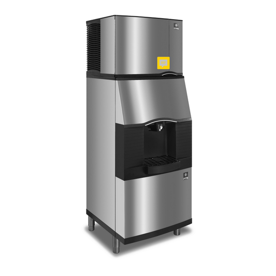
- Page 1 S Model Dispensers Installation, Operation and Maintenance Manual Caution Read this instruction before operating this equipment. Original Document Part Number 000007646 Rev 02 5/20...
-
Page 3: Safety Notices
Safety Notices Warning Follow these precautions to prevent personal injury Safety Notices during installation of this equipment: Read these precautions to prevent personal injury: • Installation must comply with all applicable equipment fire and health codes with the authority having •... - Page 4 DANGER DANGER Do not operate equipment that has been misused, abused, Follow these precautions to prevent personal injury neglected, damaged, or altered/modified from that of during use and maintenance of this equipment: original manufactured specifications. This appliance is • It is the responsibility of the equipment owner to not intended for use by persons (including children) with perform a Personal Protective Equipment Hazard reduced physical, sensory or mental capabilities, or lack of...
-
Page 5: Table Of Contents
Table of Contents Safety Notices Safety Notices ........................3 Definitions ........................3 Section 1 General Information Read This Manual ......................7 Model Numbers ........................ 7 Accessories ........................7 Adapter Kits ........................7 Included Baffle Kit ......................7 Earthquake Kits ....................... 7 Serial Plate Location ...................... - Page 6 Table of Contents (continued) Section 4 Maintenance Disassembly ........................17 Removing the Front Panel ..................... 17 Removing the Drain Pan ....................17 Disassembling the Rocking Chute/Door & Paddle Wheel Guard ........18 Disassembling the Dispenser Parts for Bin Cleaning .............19 Cleaning and Sanitizing ....................20 Monthly Sanitizing Procedure ..................
-
Page 7: General Information
These dispensers are used in conjunction with a Earthquake kits are available to secure the ice machine to the Manitowoc ice machine for automatic fill of dispenser. dispenser and the dispenser to the floor. • S160/S190 Series Dispensers are capable of storing Serial Plate Location 120 lbs. - Page 8 General Information Section 1 THIS PAGE INTENTIONALLY LEFT BLANK Part Number 000007646 Rev 02 5/20...
-
Page 9: Installation
Section 2 Installation Pre-Installation Checklist Location: Floor drain available – A floor drain for the Clearances for top and both sides of ice machine dispenser should be available. We recommend that you – Use clearances specified in the ice machine’s vent the drain at the back of the dispenser to reduce Installation, Use and Care Manual. -
Page 10: Electrical
Installation Section 2 Electrical Water Supply and Drains Warning POTABLE WATER • Water temperature must be between 40°F (4.4°C) and All wiring must conform to local, state and national codes. 90°F (32°C). • Water pressure must be between 20 psi (140 kPa) and SPECIFICATIONS 80 psi (550 kPa). -
Page 11: Installation Procedures
Section 2 Installation Installation Procedures Installation Checklist Dispenser and ice machine are level? Warning Drains are vented? Do not attempt to move a dispenser without first removing the ice machine. The combination can be unstable and Dispenser does not sit in direct sunlight? could tip, causing serious injury. - Page 12 Installation Section 2 THIS PAGE INTENTIONALLY LEFT BLANK Part Number 000007646 Rev 02 5/20...
-
Page 13: Operation
Section 3 Operation Sequence of Operation ICE PICK-UP When the customer activates the dispenser, the gearmotor The operation of the S Series ice dispenser can be divided inside the dispenser begins to turn. into three main operations. They are Dispenser Activation, The gearmotor shaft is attached to the paddle wheel inside Ice Pick-Up and Ice Delivery. -
Page 14: Room Key Card Activation
Operation Section 3 Room Key Card Activation Adjustments 1. User places ice bucket under ice chute. ADJUSTING THE COIN MECHANISM TIMER 2. User places their hotel room key card into a slot on the 1. Remove the control box cover. On the inside of the dispenser which is labeled “Insert Room Key Card”. -
Page 15: Agitation Timers
Section 3 Operation Agitation Timers TIMER WITH TEST PINS The timer is equipped with test pins. This allows you to test The agitation timer is standard equipment for the floor the timer by removing the jumper between the two pins. standing dispenser. - Page 16 Operation Section 3 THIS PAGE INTENTIONALLY LEFT BLANK Part Number 000007646 Rev 02 5/20...
-
Page 17: Maintenance
Section 4 Maintenance REMOVING THE DRAIN PAN Warning 1. The drain pan is visible when the front panel of the Dispenser is not suitable for installation in an area where dispenser is removed. a water jet could be used and must not be cleaned by a 2. -
Page 18: Disassembling The Rocking Chute/Door & Paddle Wheel Guard
Maintenance Section 4 DISASSEMBLING THE ROCKING CHUTE/DOOR & PADDLE WHEEL GUARD Warning Electric Shock Hazard Unplug unit before servicing or cleaning. 1. Remove the front panel from the dispenser. (See “Removing the Front Panel”.) 4. Lift up left end of door rod and pull rod out from right side of door. -
Page 19: Disassembling The Dispenser Parts For Bin Cleaning
Section 4 Maintenance Agitator Paddle Wheel Guard 2. Pull on the hand-removable agitator pin until it is clear of the agitator bushing. 8. Remove the paddle wheel guard from the ice dispense snout. DISASSEMBLING THE DISPENSER PARTS FOR BIN CLEANING Paddle Wheel Warning Unplug unit before servicing or cleaning. -
Page 20: Cleaning And Sanitizing
1. Remove the front panel, paddle wheel, ice chute and door assembly. 2. Mix a solution of 3 ounces (100 ml) Manitowoc cleaner per 1 gallon (4 liters) plain tap water. 3. Carefully clean all parts removed from inside the bin with this cleaner. -
Page 21: Removal Of The Gearmotor
Section 4 Maintenance Removal of the Gearmotor NOTE: The gearmotor does not have to be removed for cleaning/sanitizing. Warning Electric Shock Hazard Unplug unit before servicing or cleaning. Remove Pins 1. Remove the front panel from dispenser. (See “Removing the Front Panel”). 4. - Page 22 Maintenance Section 4 THIS PAGE INTENTIONALLY LEFT BLANK Part Number 000007646 Rev 02 5/20...
-
Page 23: Troubleshooting
Section 5 Troubleshooting Checklist If a problem arises during operation of your dispenser, Warning follow the checklists below, before calling service. Routine Unplug unit before servicing or cleaning. Ice dispenser bin adjustments and maintenance procedures are not covered contains parts that can move at any time and will cause by the warranty. -
Page 24: Ice Machine Warranty
Troubleshooting Section 5 Ice Machine Warranty Warranty For warranty information visit: www.manitowocice.com/Service/Warranty • Warranty Coverage Information • Warranty Registration • Warranty Verification Warranty coverage begins the day the ice machine is installed. WARRANTY REGISTRATION Completing the warranty registration process is a quick and easy way to protect your investment. - Page 25 Section 5 Troubleshooting THIS PAGE INTENTIONALLY LEFT BLANK Part Number 000007646 Rev 02 5/20...
- Page 26 Troubleshooting Section 5 THIS PAGE INTENTIONALLY LEFT BLANK Part Number 000007646 Rev 02 5/20...
- Page 28 Manitowoc ice 2110 south 26th street, Manitowoc, wi 54220 800-545-5720 www.Manitowocice.coM ©2022 ManitowocInc. except where explicitly stated otherwise. All rights Part Number 000007646 Rev 02 5/20 reserved.
Need help?
Do you have a question about the S160 Series and is the answer not in the manual?
Questions and answers