Table of Contents
Advertisement
Quick Links
Evaluates: MAX22005
General Description
The MAX22005PMB# (peripheral module board) provides
a Pmod™-compatible hardware solution to evaluate the
MAX22005 Twelve-Channel Configurable Industrial Analog
Input. Refer to the MAX22005 IC data sheet for more
details on the operation of the IC and its register map.
The MAX22005PMB# is most easily evaluated by con-
figuring four universal analog inputs with the
GUI
software through the
Alternatively, any SPI-compatible microcontroller, adapter
board, or FPGA can be used along with a custom driver
to evaluate the board.
The PCB dimension is just 99mm long x 23mm wide, with
the width determined by the size of the terminal block.
Note the module provides a subset of the MAX22005
features. For greater flexibility, refer to the MAX22005
Evaluation Kit.
Ordering Information
appears at end of data sheet.
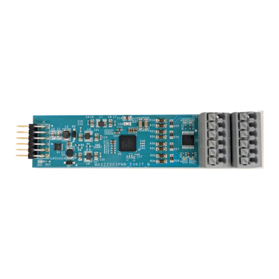
MAX22005PMB# Photo
Pmod is a registered trademark of Digilent Inc.
©
2022 Analog Devices, Inc. All rights reserved. Trademarks and registered trademarks are the property of their respective owners.
One Analog Way, Wilmington, MA 01887 U.S.A.
Click
Munich
USB2PMB2#
adapter board.
|
Tel: 781.329.4700
here
to ask an associate for production status of specific part numbers.
Features
● Easy Evaluation of the MAX22005
● Configurable as 8 Single-Ended Analog Voltage
Inputs, 4 Single-Ended Analog Current Inputs, 4
Differential Analog Voltage Inputs, 4 Multifunctional
(Universal) Analog Inputs, or Combinations Thereof
● Analog Input Voltage Range: ±12.5V
● Analog Input Current Range: ±25mA
● ±1.5kV Input Surge Protection
● Works with the USB2PMB2# Adapter and Munich
GUI Software
● Fully Assembled and Tested
● Proven PCB Layout
● RoHS Compliant
EV Kit Contents
● MAX22005PMB#
|
© 2022 Analog Devices, Inc. All rights reserved.
MAX22005PMB#
319-100889; Rev 0; 3/22
Advertisement
Table of Contents

Subscribe to Our Youtube Channel
Related Manuals for Analog Devices MAX22005


Summary of Contents for Analog Devices MAX22005
- Page 1 Pmod is a registered trademark of Digilent Inc. 319-100889; Rev 0; 3/22 © 2022 Analog Devices, Inc. All rights reserved. Trademarks and registered trademarks are the property of their respective owners. One Analog Way, Wilmington, MA 01887 U.S.A. Tel: 781.329.4700...
-
Page 2: Block Diagram
ONLY ONE TRIPLET SHOWN FOR CLARI TY MAX22005 RSTB AI4 – AI6 AI7 – AI9 AI10 – AI12 HVSS MAX22005PMB# EV Kit Files FILE DESCRIPTION Munich GUISetupV2.25.exe Munich GUI software for use with the USB2PMB2# adapter Analog Devices │ 2 www.analog.com... -
Page 3: Quick Start
Procedure This quick start procedure assumes the use of the USB2PMB2# adapter and Munich GUI software. For use with other Pmod or SPI-compatible devices, refer to the MAX22005 IC data sheet for register settings and instruc- tions. 1) Visit www.maximintegrated.com... - Page 4 PMOD000003A should appear in the list (or auto- matically get selected). Click Connect. Figure 2. USB2PMB2# and MAX22005PMB# Connection Figure 3. Choosing the MAX22005PMB# GUI in the Device Menu Figure 4. Scanning for USB2PMB Adapters and Connecting Analog Devices │ 4 www.analog.com...
- Page 5 13) In the Sample box, set the Sample Rate and Sam- side). See Figure ple Count. Example values are shown in Figure Figure 5. Example Voltage Measurement Settings and Expected Results Figure 6. Example Sample Settings Analog Devices │ 5 www.analog.com...
- Page 6 MAX22005 IC. For greater flex- the target of 0.02% Total Unadjusted Error. Refer to ibility and access to all of the MAX22005 features, refer to the MAX22005 data sheet for a description of the calibration procedure.) the MAX22005 Evaluation Kit.
- Page 7 J1 Pmod connector’s DVDD pins 6 and 12. DVDD from Pmod connections on the MAX22005PMB#. the USB2PMB2# is 3.3V. The MAX22005 IC DVDD pins are supplied directly from the J1 DVDD pins. AVDD is supplied by DVDD through a Pi filter. HVDD and HVSS are supplied by DVDD through a dual boost converter, the MAX8614A.
-
Page 8: Connector - Pin
J3 - 3 No external surge suppression is needed as all the J3 - 4 10 (CH4) AI10 MAX22005 IC analog inputs are protected against up to ±1.5kV surge pulses as per IEC61000-4-5 using series J3 - 5 AI12 4.75kΩ 0.4000W resistors. -
Page 9: Ordering Information
“grab and drag” or “zoom in on selection,” print, and Munich GUI version number. save, graph settings, zoom in, zoom out, default zoom Figure 10. MAX22005PMB# GUI Software Ordering Information PART TYPE MAX22005PMB## Peripheral Module #Denotes RoHS compliance. Analog Devices │ 9 www.analog.com... - Page 10 CONVERTER FOR CCD; TDFN14 EVKIT PART - IC; RX16; TWELVE-CHANNEL FACTORY- MAX22005 MAXIM MAX22005 CALIBRATED CONFIGURABLE INDUSTRIAL ANALOG INPUT; QFN48 IC; ASW; QUAD NO SPST; +70V ANALOG SWITCH; MAX14757EUE+ MAXIM MAX14757EUE+ TSSOP16 MAX22005PMB MAXIM PCB:MAX22005PMB TOTAL Analog Devices │ 10 www.analog.com...
- Page 11 MAX22005PMB# Evaluates: MAX22005 MAX22005PMB# Schematic Analog Devices │ 11 www.analog.com...
- Page 12 MAX22005PMB# Evaluates: MAX22005 MAX22005PMB# PCB Layout Diagrams 1” MAX22005PMB# PCB Layout—SILK_TOP 1” MAX22005PMB# PCB Layout—TOP 1” MAX22005PMB# PCB Layout—DGND_AGND1 Analog Devices │ 12 www.analog.com...
- Page 13 MAX22005PMB# Evaluates: MAX22005 MAX22005PMB# PCB Layout Diagrams (continued) 1” MAX22005PMB# PCB Layout—HVDD_HVSS 1” MAX22005PMB# PCB Layout—DVDD_AVDD 1” MAX22005PMB# PCB Layout—DGND_AGND2 Analog Devices │ 13 www.analog.com...
- Page 14 MAX22005PMB# Evaluates: MAX22005 MAX22005PMB# PCB Layout Diagrams (continued) 1” MAX22005PMB# PCB Layout—BOTTOM 1” MAX22005PMB# PCB Layout—SILK_BOT Analog Devices │ 14 www.analog.com...
-
Page 15: Revision History
Information furnished by Analog Devices is believed to be accurate and reliable. However, no responsibility is assumed by Analog Devices for its use, nor for any infringements of patents or other rights of third parties that may result from its use.Specifications subject to change without notice. No license is granted by implicationor otherwise under any patent or patent rights of Analog Devices.
Need help?
Do you have a question about the MAX22005 and is the answer not in the manual?
Questions and answers