
Related Manuals for Frico Soloclim


Summary of Contents for Frico Soloclim
- Page 1 Original instructions Soloclim ..11 ..19 ..10 ..12 ..14 ..16 ..18 ..20 ..22 ..24 ..26...
- Page 2 Soloclim The introduction pages consist mainly of pictures. For translation of the English texts used, see the respective language pages. Introduktionssidorna består huvudsakligen av bilder. För översättning av de engelska texter som används, se respektive språksidor. Introduksjonssidene består hovedsakelig av bilder. For oversettelse av de engelske tekstene, se de respektive språksidene...
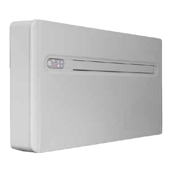
- Page 3 Soloclim Fig.1 Components 1. Touch screen control panel 13.Room temperature sensor 2. Air outlet deflector 14.Internal exchanger 3. Front panel 15.External fan 4. Intake grille 16.Condensation pump 5. Side panel 17.External exchanger 6. External air intake 18.Maximum level float (not SC1 DCI-MINI) 7.
- Page 4 Soloclim Fig.2 Included in delivery A. Outside grilles for air inlet and outlet (2 pcs) Fig.6 F. Paper drilling template Fig.4 B. Screws and plugs kit (6 pcs) G.CR2025 3V remote control battery C. Wall mounting bracket H. Plastic sheet for wall duct (2 pcs) Fig.5 D.Manual...
- Page 5 Soloclim Fig.4 Drilling template SC21DCIN, SC23DCIN(1000) A. Holes for M8 plugs D.Ø18 mm condensate drain B. Electrical connection area E. Hole for anchor bracket C. Ø162 mm holes for air ducts F. NOT USED SC17DCIN-MINI...
- Page 6 Soloclim Fig.5 Air ducts Plastic sheets for air ducts Fig.6 Wall grilles A. Chain B. Flange C. Spring D. Outside air grill...
- Page 7 Soloclim Fig.7 Mounting the unit 0 ° 1° m a x . 1. Spirit level 2. Wall bracket 3. Fixing screw 4. Expansion plug 5. Interlocking points Fig.8 Drainage 1. Drainage tube 0,6 m (Ø18 mm outside, Ø13 mm inside)
- Page 8 Soloclim Fig.8b Drainage 30 0 m m Fig.9 Opening the unit double sided tape Fig.10 Access to the terminal block Wiring diagram Grey Brown Yellow-Green Blue Presence contact Neutral Phase System main switch Earth connection...
- Page 9 Soloclim Fig.11 High wall installation SCSFH1 Adjustment of deflector (changing air flow direction) 180° 18 0 ° Accessories Art. no Type WxHxD [mm] 282045 SCKEG162 180x180x20 SCRPK 282046 230x120x170 990547 SCSFH1 940x15x155 SCKEG162 SCRPK 999945 SCKL* 1006x505x165 999946 SCKR* 1006x505x165 *) See separate manual.
-
Page 10: Technical Specifications
Soloclim Technical specifications Art. no Type Cooling Heat Voltage Refrigerant WxHxD Weight* output* output* amount [kW] [kW] [kg] [mm] [kg] 282044 SC17DCI-MINI 2,35 2,40 3,01 3,15 230V~ 0,14 (R290) 810x549x165 283421 SC21DCIN 2,64 2,64 3,29 3,31 230V~ 0,65 (R32) 1010x549x165... -
Page 11: General Instructions
• Do not use flammable cleaners on the unit. consumption. Protection class: IPX0. • Never pour or spray water over the unit. Soloclim horizontal is designed only for use with R32 gas as the designated refrigerant, with the exception • Component parts are designed for the refrigerant and of SC17DCI-MINI which is designed only for use with non-incentive and non-sparking. - Page 12 Mounting Soloclim is designed for indoor installation on an exterior wall. During all handling, the unit must be kept in upright position. The unit is delivered with a drilling template for the necessary mounting holes. Fig.4. The product must be mounted in such a way to allow future service and maintenance.
-
Page 13: Electrical Installation
9. Press the deflector key on the display for 10 seconds. Electrical installation 10. The symbol "dn" appears (low wall) flashing. Soloclim is equipped with a 1,5 metre long cord with plug 11. Press the deflector key again. for connection to an earthed power socket. The power 12. -
Page 14: Control Panel
Soloclim Control Soloclim is controlled by the touch-screen control panel on the front of the unit or by the supplied remote control. Control panel Remote control Setpoint Heating mode Comfort mode Night Increase / up Decrease / down Air deflector... - Page 15 Soloclim Dehumidification mode Setting power In this mode, the unit dehumidifies the room. The unit has five power settings - Minimum, Selecting this mode is useful during mid-seasons, Medium, Maximum, Dual Power and Automatic - i.e. on rainy days when the temperature is selected by pressing this key sequentially.
-
Page 16: Maintenance
Soloclim Remote control Packaging The remote control has a working range of approximately Packaging materials are chosen with consideration to the 8 metres. Its top must point towards the display of the environment and are therefore recyclable. unit. The reception of the command is confirmed by a beep and by the display. -
Page 17: Trou Leshooting
Check that the system main switch has not been tripped (if it The unit does not work. has, reset it). If the problem repeats immediately, contact Frico Technical support and do not try to make the unit work. The remote control does not work. - Page 18 In the event of an alarm, check that the tube is not bent or obstructed, thus preventing the water from flowing out. If the fault cannot be rectified, please contact Frico Technical support specifying the error code to simplify intervention.
- Page 19 Main o Frico AB Tel: +46 31 336 86 00 Industrivägen 41 SE-433 61 Sävedalen mailbox@frico.se Sweden www.frico.net or latest updated information and information a out your local contact www frico net...
Need help?
Do you have a question about the Soloclim and is the answer not in the manual?
Questions and answers