Table of Contents
Advertisement
Available languages
Available languages
Quick Links
Betriebsanleitung/ Sicherheitshandbuch
Instruction Manual/ Safety Manual
Instruction de service/ Manuel de sécurité
Istruzioni per l'uso/ Manuale di sicurezza
Überwachter Schallgeber/ Monitored Sounder
Sirène surveillée/ Sirene controllate
DS5-SIL / DS10-SIL (DC)
Pfannenberg GmbH
·
Werner-Witt-Straße 1
D- 21035 Hamburg
·
Tel.: +49/ (0)40/ 734 12-0
Fax: +49/ (0)40/ 734 12-101
Service@pfannenberg.com
http://www.pfannenberg.com
12/2021
Datei/ file name:085501929k de-en-fr-it.docx
Seite / page: 1 / 66
Zeichnungsnr./ Drwg-no.: 30007-008-12k
Rev-No.: ÄAN03203
Advertisement
Chapters
Table of Contents

Related Manuals for Pfannenberg 23106100601


Summary of Contents for Pfannenberg 23106100601
- Page 1 Instruction Manual/ Safety Manual Instruction de service/ Manuel de sécurité Istruzioni per l’uso/ Manuale di sicurezza Überwachter Schallgeber/ Monitored Sounder Sirène surveillée/ Sirene controllate DS5-SIL / DS10-SIL (DC) Pfannenberg GmbH · Werner-Witt-Straße 1 D- 21035 Hamburg · Tel.: +49/ (0)40/ 734 12-0 Fax: +49/ (0)40/ 734 12-101 Service@pfannenberg.com...
-
Page 2: Table Of Contents
Inhalt Kurzbeschreibung des Systems ........................... 3 Bestimmungsgemäße Verwendung ........................4 Technische Daten ..............................4 3.1. Montagezeichnung ............................4 3.2. Elektrische Daten ............................4 3.3. Mechanische Daten ............................5 3.4. Klimatische Daten ............................5 3.5. Akustische Daten: ............................5 Sicherheitshandbuch/ Safety Manual ........................7 4.1. -
Page 3: Kurzbeschreibung Des Systems
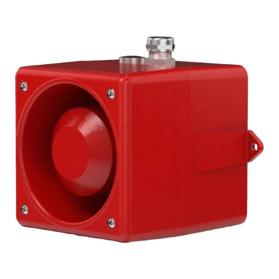
1. Kurzbeschreibung des Systems Bei den Schallgebern der Typenreihe DS..-SIL handelt es sich um akustische Warneinrichtungen zur Signalisierung von Gefahrenzuständen in sicherheitsrelevanten Anwendungen, z.B. als Bestandteil eines E/E/PE-Systems (nach EN61508). Abb. 1 Übersicht Die Schallgeber sind für robuste Anforderungen unter Industriebedingungen konstruiert und können einen Schallpegel bis maximal 114 dB(A) erzeugen. -
Page 4: Bestimmungsgemäße Verwendung
2. Bestimmungsgemäße Verwendung Durch eine Gefährdungs- und Risikoanalyse können Gefahren, die von den Einrichtungen ausgehen, ermittelt wer- den. Wenn ein Gefahrenzustand abzuwenden ist, können die Schallgeber als Bestandteil eines sicherheitstechni- schen Systems (Safety Instrument System - SIS) bis zum Sicherheitsintegrationslevel 2 (SIL 2) verwendet werden. -
Page 5: Mechanische Daten
3.3. Mechanische Daten IP 66 / 67 (EN 60529) Schutzart Schutzklasse Öffnung des Schalltrichters nicht nach oben richten Einbaulage Kabeleinführung 2x M20x1,5 8 – 12 mm Klemmbereich der Kabelverschraubung Federzugbügel/ Cage Clamp 0,08-2,5mm² (AWG28-12), Anschlussklemmen (AWG12 THHN,THWN) Gewicht 1,95 Kg Al-Druckguss GD-Al Si12 Cu Material des Gehäuses Eloxal, Polyester-Pulverbeschichtung RAL 3000, feuerrot... - Page 6 Sirene / Siren / Sirène montante et descendante ON ON ON ON Sirene / Siren / Sirène montante et descendante ON ON ON - Hoechst - Sirene / Siren / Sirène montante et descendante ON ON ON ON ON - NF C 48-265 - Auswahl der frei belegbaren Tonkombinationen in Stufe 2, 3 und 4 –...
-
Page 7: Sicherheitshandbuch/ Safety Manual
EN ISO 13849-1 (in Anlehnung) Sicherheitsbezogene Teile von Steuerungen Mit der Kennzeichnung des Gerätes mit dem CE-Zeichen bestätigt die Firma Pfannenberg GmbH die Erfüllung der gesetzlichen Anforderungen der zutreffenden EG-Richtlinien. Der Schallgeber DS..-SIL erfüllt die Anforderungen an die funktionale Sicherheit nach IEC 61508 bzw. IEC61511. -
Page 8: Qualifikation
4.3. Qualifikation Handhabungen entsprechend dieser Betriebsanleitung und des Sicherheitshandbuchs dürfen nur durch ausgebildetes und vom Anlagenbetreiber autorisiertes Elektro-Fachpersonal durchgeführt werden. Die Integration des Schallgebers in eine Anwendung ist entsprechend der Regeln der funktionalen Sicherheit entspre- chend IEC 61508 bzw. IEC 61511 durchzuführen. Wiederholungsprüfungen (Proof Test) und deren Nachweis dürfen nur durch autorisiertes Elektro-Fachpersonal durchgeführt werden. -
Page 9: Verwendung Als Akustisches Warnsystem Bei Erfassung Gefährlicher Zustände
4.4.2. Verwendung als akustisches Warnsystem bei Erfassung gefährlicher Zustände Bei der Verwendung als Warnsystem nach Erfassung gefährlicher Zustände ist die Erzeugung eines akustischen Warnsignals als Sicherheitsfunktion zu bewerten. Eine Messung erfasst einen gefährlichen Zustand und leitet den sicheren Zustand durch Ansteuerung des akustischen Warnsystems ein (Personal/ Bediener ist gewarnt). Hinweis: Die Warnung von Personen ist eine willensabhängige Maßnahme, da sie eine willentliche Handlung einer oder mehrerer Personen erfordert. -
Page 10: Verwendung Als Akustisches Warnsystem Mit Testfunktion
Kategorie Die Überwachung der Funktion des Schallgebers wird bei der Wiederholungsprüfung (Proof Test) genutzt. Der „Proof Test“ ist im Kapitel der Bedienungsanleitung / Sicherheitshandbuch beschrieben. *Die PFD für abweichende Intervalle des Proof Tests kann in diesem Fall durch einfache Multiplikation des Wertes für 1 Jahr mit den vorgesehenen Jahresabständen zwischen den Tests ermittelt werden. -
Page 11: Zeitliche Abhängigkeiten
a) Ein Einschalten der Versorgungsspannung des Schallgeberkanals hat im fehlerfreien Zustand ein Ansteuern des MOS-Relais (Der Ausgang des MOS-Relais wird niederohmig.) zur Folge. Dies erfolgt mit einer Verzöge- rung von 0,2 Sekunden. Voraussetzung ist, dass eine Tonart mit Hilfe des Kodierschalters für die Tonarten- wahl ausgewählt wurde oder bei der Option „externe Tonartenwahl“... -
Page 12: Funktionstest Anlaufwarnung
a) Einschalten der Spannungsversorgung der Überwachung bei nicht aktiviertem Schallgeberkanal, (Kann je nach Anwendung entfallen, wenn die Überwachung ständig an der Versorgung anliegt) b) Überprüfen, ob das Störmelderelais >0,5s nach dem Einschalten hochohmig ist, Einschalten des Schallgeberkanals (Ton wird erzeugt) d) Überprüfen, ob das Störmelderelais nach >... -
Page 13: Wiederholungsprüfungen (Proof Test)
4.10. Wiederholungsprüfungen (Proof Test) In regelmäßigen Abständen sind manuelle Kontrollen der Sicherheitsfunktion und des visuellen Zustandes des Schall- gebers vorzunehmen. Diese Prüfung dient der Identifizierung von nicht automatisch erkannten, gefährlichen Fehlern und des Allgemeinzustandes des Gerätes. Bei Nichtausführung des Proof Tests in den erforderlichen, festgelegten, zeitlichen Abständen führt das zum Verlust der erreichbaren SIL Einstufung. -
Page 14: Anforderungen An Die Installation Und Inbetriebnahme
4.13. Anforderungen an die Installation und Inbetriebnahme a) Der Schallgeber entspricht dem Stand der Technik und wurde unter Berücksichtigung der einschlägigen Vorschriften und Richtlinien konstruiert. b) Die Betriebsanleitung und das Sicherheitshandbuch richten sich an ausgebildetes und autorisiertes Elektro- Fachpersonal. Deren Inhalt muss dem Fachpersonal zugänglich gemacht und umgesetzt werden. Der elektrische Anschluss darf nur von hierfür autorisierten Personen durchgeführt werden. -
Page 15: Anschlussbedingungen
Die Geräte sind mit einem Verpolungsschutz ausgestattet. Keine Funktion bei Verpolung der Anschlüsse! Abb. 10 Anschlussbelegung und Bedienelemente Klemmenbelegung X1 L - Betriebsspannung Schallgeber + 24V DC Betriebsspannung Schallgeber N - Betriebsspannung Schallgeber -0V DC Betriebsspannung Schallgeber Klemmenbelegung X3 + 24V DC Betriebsspannung Überwachungskanal L - Betriebsspannung Überwachungskanal N - Betriebsspannung Überwachungskanal -0V DC Betriebsspannung Überwachungskanal... -
Page 16: Störungsbeseitigung
Fehler, die die funktionale Sicherheit betreffen sind an den Hersteller zu melden. Bitte verwenden Sie für eine rei- bungslose Abwicklung das im Anhang befindliche Formular und senden Sie dieses an eine der folgenden Verbindun- gen. Post: Pfannenberg GmbH Service Werner-Witt-Str.1 D-21035 Hamburg E-Mail: Service@Pfannenberg.com... - Page 17 Content Brief description of the system .......................... 18 Intended use ................................. 19 Technical data ..............................19 3.1. Installation drawing ............................19 3.2. Electrical data .............................. 19 3.3. Mechanical data ............................20 3.4. Climatic data ..............................20 3.5. Acoustic Data .............................. 20 Safety Manual ...............................
-
Page 18: Brief Description Of The System
1. Brief description of the system The sounders of the DS..-SIL series are audible warnings for the signalling of dangerous situations in safety relevant applications, e.g. as an intrinsic part of an E/E/PE system (according to EN61508). Operational voltage Acoustic (for signal devices signal Sounder channel... -
Page 19: Intended Use
2. Intended use With a danger and risk analysis, dangers created in the installation can be ascertained. If a dangerous situation is to be avoided, then the sounders can be used as an integral part of a technical safety system (Safety Instrument System - SIS) up to safety integration level 2 (SIL 2). -
Page 20: Mechanical Data
3.3. Mechanical data IP 66 / 67 ( EN 60529 ) Degree of protection Protection class Opening of bell mouth shall not point upwards Mounting position Cable entry 2x M20x1,5 8 – 12 mm Clamp range of cable gland Cage Clamp 0,08-2,5mm² (AWG28-12), Terminals (AWG12 THHN,THWN) Weight... - Page 21 Sirene / Siren / Sirène montante et descendante ON ON ON ON Sirene / Siren / Sirène montante et descendante ON ON ON - Hoechst - Sirene / Siren / Sirène montante et descendante - NF C 48-265 ON ON ON ON ON Auswahl der frei belegbaren Tonkombinationen in Stufe 2, 3 und 4 –...
-
Page 22: Safety Manual
EN ISO 13849-1 (following) Safety-related parts of control systems With the identification of the device with the CE sign, Pfannenberg GmbH confirms the fulfilment of the legal require- ments of the applicable EC guidelines. The DS ..-SIL sounder fulfils the requirements of the functional safety according to IEC 61508/IEC 61511. -
Page 23: Evaluation
4.4. Evaluation 4.4.1. Use as a starting alarm of machines For use as a starting alarm of machines, the function of the generation of the acoustic warning signal in the sounder channel is to be assessed as a function of the machine. The safe condition is reached when the acoustic warning sys- tem works reliably. -
Page 24: Use As Acoustic Warning System Without Test Function
The diagnosis can only be taken into account if there is regular, automated function checking, the minimum interval of which must be in accordance with approx. ten to one hundred times the requirement rate according to IEC/EN61508. This possibility is only available in low demand mode and is further described and evaluated in section 4.4.2.2. The acoustic warning system with diagnosis function is implemented as follows: a) A measurement (input (1), logic (2) records a dangerous condition and activates the acoustic warning system (output (3) -
Page 25: Use As Acoustic Warning System With Test Function
* The PFD for deviating intervals of the proof test can be ascertained in this case by simply multiplying the value for 1 year by the envisaged annual intervals between the tests. Ensure that the limit value for the entire safety chain is not exceeded. 44% of the SIL2 level is already used for a proof test interval of 4 years. -
Page 26: Operating Behaviour Of The Monitoring Equipment
4.5. Operating behaviour of the monitoring equipment For the evaluation of the monitoring a superior control system, which is in accordance with the functional safety re- quirements of IEC/EN61508, must be available. The control system must be capable of carrying out a fault analysis according to the capacity of failure in connection with the operational condition of the sounder. -
Page 27: Function Test
Tone Tone is not generated Tone cancelled Operating voltage Sounder channel Operating voltage * dependent on the tone Monitoring circuit and cause of fault Alarm output Fig. 9 Function time diagram with fault 4.7. Function test For applications in 'low demand mode' with safety requirements an automatic function test should be carried out with regular intervals. -
Page 28: Proof Test
4.10. Proof Test Manual checks of the safety function and the visual condition of the sounder are to be performed in regular intervals. This test serves to identify dangerous faults that are not automatically detected and the general condition of the de- vice. -
Page 29: Limits Of Use
4.12. Limits of use The limits that can be taken from the technical data in section are to be kept. The limits for the calculation of the safety integrity of the sounder in systems is to be taken from section 4.4. Changes to the sounder are only possible via the manufacturer. -
Page 30: Connection Assignment
4.14. Connection assignment Monitoring Überwachungs- circuit schaltung Sounder Schallgeber Sounder Schallgeber- 2 4 6 8 Channel kanal Operational Betriebs- spannung voltage Monitoring Überwachungs- circuit Option schaltung 2 4 6 8 Option TAS Operational Betriebs- spannung voltage Selector switch S1 for Kodierschalter setting tones Tonartenwahl... -
Page 31: Connection Requirements
If the sounder is defective, it should be repaired in the production plant. Only original replacement parts can be used as replacements. Faults that affect the functional safety are to be reported to the manufacturer. For a smooth process, please use the form attached and send it to the following address. Post: Pfannenberg GmbH Service Werner-Witt-Str.1 D-21035 Hamburg E-Mail: Service@Pfannenberg.com... - Page 32 Sommaire Utilisation conforme ............................34 Caractéristiques techniques ..........................34 3.1. Plan de montage ............................34 3.2. Caractéristiques électriques ........................34 3.3. Caractéristiques mécaniques ........................35 3.4. Caractéristiques climatiques ........................35 3.5. Caractéristiques acoustiques ........................35 Manuel de sécurité (Safety Manual) ........................37 4.1.
- Page 33 1. Description rapide du système Les sirènes de la série DS..-SIL sont des dispositifs d'alarme sonore destinés à signaliser des situations dangereuses dans des applications relatives à la sécurité, comme par exemple, en tant que composants d'un système E/E/PE (se- lon EN61508).
-
Page 34: Utilisation Conforme
2. Utilisation conforme Une analyse des dangers et des risques permet de déterminer les risques découlant des installations. Dans le do- maine de prévention et d'évitement des risques, les sirènes peuvent être utilisées en tant que composants d'un sys- tème instrumenté de sécurité (Safety Instrument System - SIS) jusqu'au niveau d'intégrité de sécurité 2 (SIL 2). Les sirènes étant intégrées de manières très différentes dans diverses architectures de sécurité, il convient d'observer ces dernières sous différents aspects. -
Page 35: Caractéristiques Mécaniques
3.3. Caractéristiques mécaniques IP 66 / 67 (EN 60529 ) Indice de protection Type de protection L'ouverture du diffuseur ne doit pas être dirigée vers le haut Position de montage 2x M20x1,5 Presse-étoupe 8 – 12 mm Borne de fixation de câble à vis Etrier à... - Page 36 Sirene / Siren / Sirène montante et descendante ON ON ON ON Sirene / Siren / Sirène montante et descendante ON ON ON - Hoechst - Sirene / Siren / Sirène montante et descendante - NF C 48-265 ON ON ON ON ON Sélection des combinaisons de sons libres au niveau 2, 3 et 4.
-
Page 37: Manuel De Sécurité (Safety Manual)
EN ISO 13849-1 (dans le sens) Parties des systèmes de commande relatives à la sécurité La société Pfannenberg GmbH confirme avec le marquage CE de l'appareil sa conformité aux exigences légales des directives CE correspondantes. La sirène DS..-SIL remplit les conditions de sécurité fonctionnelle de la norme CEI 61508 ou encore CEI 61511. -
Page 38: Qualification
4.3. Qualification Toutes les manipulations, correspondantes à ces instructions de service et au manuel de sécurité, doivent unique- ment être exécutées par du personnel qualifié en électricité et autorisé par l'exploitant de l'installation. L'intégration de cette lampe à éclairs dans une application doit être conforme aux règles de la sécurité fonctionnelle des normes CEI 61508 et CEI 61511. -
Page 39: Utilisation Comme Système D'avertissement Acoustique Lorsque Des Conditions Dangereuses Sont Détectées
3,9 x 10 94,9 MTTFd >100 λ Circuit de diagnostic λ Circuit de diagnostic λ Circuit de diagnostic 7459 Type d'architecture IEC/EN61508 Adéquation du système à l'application dans des boucles de sécu- rité jusqu'au niveau SIL Catégorie (DIN EN ISO13849) PL (DIN EN ISO13849 4.4.2. - Page 40 sonore (sortie - position 3) et le canal de diagnostic (module de diagnostic - position 4). Il convient d'observer que, face au système global, la somme de toutes les valeurs PFH ou encore PFD doit correspondre au niveau d'intégrité de sécurité requis. File name:085501929k de-en-fr-it.docx page: 40 / 66 Dessin no.: 30007-008-12k...
-
Page 41: Application Comme Système D'alerte Sonore Sans Fonction De Test
4.4.2.1. Application comme système d'alerte sonore sans fonction de test La fonction de sécurité, c.-à-d. l'émission d'un signal d'avertissement, est ici réalisée par un système à canal unique (1oo1 selon CEI/EN61508) sans prise en compte de la fonction diagnostique, comme c'est également décrit au cha- pitre 4.2. -
Page 42: Comportement En Service Du Dispositif De Surveillance
Type d'architecture Adéquation du système à l'application dans des boucles de sécurité jus- qu'au niveau Catégorie (DIN EN ISO13849) PL (DIN EN ISO13849) Le système, y compris la prise en compte des déclenchements de tests et du module de diagnostic, est considéré comme un système de type B d'une technique de gestion maître, en raison de son intégration complexe dans les pro- cessus de contrôle de l'exploitant. -
Page 43: Dépendances Temporelles
4.6. Dépendances temporelles Tension de service Canal de signal sonore * dépend du type de son, no- Tension de service tamment 0,2 s pour les sons Circuit de surveillance continus, et 2,5 s max. pour les intervalles longs de sons intermittents Sortie d’alarme ** uniquement valable pour l'arrêt autonome des sons... -
Page 44: Temps De Sécurité Du Process
Les deux systèmes partiels, à savoir le canal de la sirène et le circuit de surveillance, possèdent des raccords de ten- sion d’alimentation distincts. De cette manière, il est possible d’effectuer un contrôle de la fonction en procédant de la manière suivante (dépendances temporelles, voir Fig. -
Page 45: Configuration Du Matériel
g.) Type de son avec Lorsque l'option « sélection externe de types de sons » est utilisée, l'opé- option TAS ration de contrôle « f.) Type de son » doit être répétée pour tous les types de sons complémentaires utilisés dans l'application. h.) Contrôle du niveau Mesure ou appréciation du niveau sonore par un groupe représentatif de sonore... -
Page 46: Affectation Des Broches
Le fonctionnement correct de la sirène doit être vérifié à la première mise en service, à la remise en service et après chaque réparation. La fonction de sécurité doit faire l'objet d'une validation particulière. Pour cela, il faut déclencher le test de fonctionnement comme décrit au chapitre 4.7. La tension d'alimentation indiquée sur la plaque signalétique doit être vérifiée avant la mise en service. -
Page 47: Conditions De Raccordement
Option : Sélection externe des sons par tension de commande – abréviation -TAS Sirène Schallgeber Son de base Tension de Niveau Betriebs- service spannung Niveau Niveau x = fermé Option Fig. 11 Affectation des broches avec l'option TAS Affectation des bornes + 24V DC Tension de commande Son niveau 2 (Option : Sélection + 24V DC Tension de commande Son niveau 2... -
Page 48: Élimination Des Erreurs
Les erreurs qui entravent la sécurité fonctionnelle doivent être signalées au fabricant. Pour permettre un traitement rapide de votre demande, nous vous prions d'utiliser le formulaire joint en annexe et d'envoyer celui-ci aux coordon- nées suivantes. Post: Pfannenberg GmbH Service Werner-Witt-Str.1 D-21035 Hamburg E-Mail: Service@Pfannenberg.com... - Page 49 Indice Breve descrizione del sistema ..........................50 Utilizzo conforme alle disposizioni ........................50 Dati tecnici ................................51 3.1. Schema di installazione ..........................51 3.2. Dati elettrici ..............................51 3.3. Dati meccanici ............................. 52 3.4. Dati climatici ..............................52 3.5. Dati acustici ..............................52 Manuale di sicurezza/ Safety Manual .........................
-
Page 50: Breve Descrizione Del Sistema
1. Breve descrizione del sistema Le sirene della serie DS..-SIL sono dispositivi di allarme acustici per la segnalazione di situazioni di pericolo in appli- cazioni rilevanti per la sicurezza, ad es. come parte integrata di un sistema E/E/PE (secondo EN61508). Tensione d’esercizio Segnale (in caso di segnalazione) -
Page 51: Dati Tecnici
Poiché il modo in cui le sirene vengono integrate nelle varie architetture di sicurezza differisce di caso in caso, vanno considerate sotto aspetti differenti. Le seguenti applicazioni sono descritte nel manuale di sicurezza: • Utilizzo come segnalazione di avviamento macchina o simile applicazione (vedere capitolo 4.4.1) •... -
Page 52: Dati Meccanici
3.3. Dati meccanici IP 66 / 67 (EN 60529) Grado di protezione Classe di protezione L’apertura della tromba non deve essere Posizione di montaggio rivolta verso l’alto 2x M20 x 1,5 Entrata cavo 8 – 12 mm Campo di serraggio del pressacavo Morsetto a molla/ Cage Clamp 0,08-2,5 mm²... - Page 53 Sirena ON ON ON ON Sirena - Hoechst - ON ON ON Sirena - NF C 48-265 - ON ON ON ON ON Selezione delle combinazioni libere di suoni per i livelli 2, 3 e 4 – Per la programmazione vedi sotto Sirena ON ON ON...
-
Page 54: Manuale Di Sicurezza/ Safety Manual
EN ISO 13849-1 (in conformità) Parti di sicurezza di dispositivi di controllo L’apparecchio è contrassegnato dal marchio CE. Con esso Pfannenberg GmbH attesta che l’apparecchio è conforme ai requisiti previsti dalle corrispondenti Direttive CE. La sirena DS..-SIL soddisfa i requisiti in materia di sicurezza funzionale delle norme IEC61508 e IEC61511. -
Page 55: Qualifica
4.3. Qualifica Tutti gli interventi conformi alle presenti istruzioni operative e al manuale di sicurezza devono essere effettuate esclu- sivamente da elettricisti specializzati, autorizzati dal gestore dell’impianto. L’integrazione della sirena in un’applicazione deve essere eseguita secondo le regole della sicurezza funzionale. (IEC 61508 e IEC61511) I test periodici (proof test) e la rispettiva prova devono essere effettuati esclusivamente da elettrici specializzati auto- rizzati. -
Page 56: Utilizzo Come Sistema Acustico Di Allarme Nel Rilevamento Degli Stati Di Pericolo
3,9 x 10 94,9 MTTFd >100 anni λ Circuito di diagnosi λ Circuito di diagnosi λ Circuito di diagnosi 7459 Tipo di architettura IEC/EN61508 Idoneità del sistema all’uso in loop di sicurezza fino al livello SIL Categoria (DIN EN ISO13849) PL (DIN EN ISO13849 4.4.2. -
Page 57: Utilizzo Come Sistema Acustico Di Allarme Senza Funzione Di Test
4.4.2.1. Utilizzo come sistema acustico di allarme senza funzione di test Alla funzione di sicurezza, ovvero all’emissione di un segnale di allarme, provvede un sistema monocanale (1oo1 se- condo IEC/EN61508) senza tener conto della funzione di diagnostica, di cui al capitolo 4.2. -
Page 58: Utilizzo Come Sistema Acustico Di Allarme Con Funzione Di Test
4.4.2.2. Utilizzo come sistema acustico di allarme con funzione di test Questa valutazione vale solo per sistemi con richiesta bassa. Viene presa in considerazione la funzione di test, di cui al capitolo 4.7. Essa deve essere eseguita in modo automatico e con una frequenza minima di 10 ... 100 volte del tasso di richiesta anticipato. -
Page 59: Caratteristica Operativa Del Dispositivo Di Sorveglianza
4.5. Caratteristica operativa del dispositivo di sorveglianza Per la valutazione del dispositivo di sorveglianza è necessario un sistema di gestione elettronica principale che è con- forme ai requisiti di sicurezza della norma IEC/EN61508. Il sistema di gestione elettronica deve essere in grado di eseguire l’analisi dei guasti in base all’uscita segnalazioni guasti in relazione allo stato operativo della sirena. -
Page 60: Test Funzionale
4.7. Test funzionale Le applicazioni in “low demand mode“ con richiesta di sicurezza richiedono l’esecuzione periodica e automatica di test funzionali. Gli intervalli di testo sono riportati nel capitolo 4.4.2.2. I due sistemi parziali - il canale della sirena e il circuito di sorveglianza - hanno collegamenti di tensione di alimenta- zione separati. -
Page 61: Configurazione Hardware
Verifica Operazione Istruzioni Controllo a.) Alloggiamento Danni meccanici e da corrosione, fissaggio in posizione visivo b.) Cono di emissione Non coperto, né ostruito del suono c.) Passacavo Serraggio corretto, buona tenuta con il cavo Funzione d.) Test funzionale - Esecuzione manuale, graduale, dei singoli passaggi del test, di cui al capi- manuale acustica tolo... -
Page 62: Requisiti In Ambito Di Installazione E Messa In Funzione
4.13. Requisiti in ambito di installazione e messa in funzione La sirena è stata costruita secondo tecnologie all’avanguardia e in conformità ai regolamenti e alle direttiva perti- nenti. Le istruzioni per l’uso e il manuale di sicurezza sono destinati agli elettricisti specializzati, qualificati e autorizzati. Questi elettricisti specializzati devono avere sempre a portata di mano le istruzioni per l’uso e il manuale di sicu- rezza e attenersi a quanto previsto dal corrispettivo contenuto. -
Page 63: Assegnazione Delle Connessioni
4.14. Assegnazione delle connessioni Circuito di sor- Überwachungs- veglianza schaltung Sirena Schallgeber Schallgeber- 2 4 6 8 Canale sirena kanal Tensione Betriebs- d’esercizio spannung Option Circuito di Überwachungs- sorveglianza schaltung 2 4 6 8 Opzione TAS Option TAS DIP switch S1 esterna del tipo di Kodierschalter Tensione... -
Page 64: Condizioni Per La Connessione
Opzione Selezione esterna del tipo di suono mediante tensione di controllo – Breve descrizione -TAS Sirena Schallgeber Condiz. amb. Tensione Betriebs- d’esercizio spannung Suono di base Suono Suono Option Suono chiuso Fig. 11 Assegnazione delle connessioni, opzione TAS Assegnazione morsetto X3 + 24 V CC tensione di controllo suono livello 2 (Opzione Selezione + 24 V CC tensione di controllo suono livello 2... -
Page 65: Eliminazione Dei Guasti
Eventuali guasti che compromettono la sicurezza funzionale devono essere segnalati al produttore. Per permettere il trattamento rapido di eventuali richieste, compilare il modulo in allegato e inviarcelo al seguente indirizzo. Indirizzo Pfannenberg GmbH postale: Service Werner-Witt-Str.1 D-21035 Hamburg E-mail: Service@Pfannenberg.com... -
Page 66: Anhang Formular „ Service Fehlererfassung
Da allegare alla restituzione dell’apparecchio o da utilizzare per segnalare un guasto 1. Reparatur-Anforderung/ Repair request/ Ja/ Yes Nein/ No Demande de réparation/ Richiesta di riparazione 2. Pfannenberg Ref. Nr./ Pfannenberg Ref. No.: Datum/ Date/ Date/ (wenn bekannt/ If known/ Si connue/ Se conosciuto) Data : 3.
Need help?
Do you have a question about the 23106100601 and is the answer not in the manual?
Questions and answers