Pfannenberg DS10-SIL Instruction Manual/Safety Manual
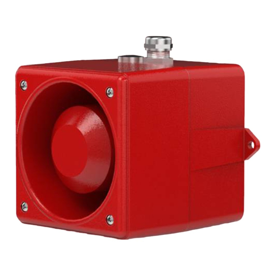
Monitored sounder
Hide thumbs
Also See for DS10-SIL:
- Instruction manual (68 pages) ,
- Instruction manual/safety manual (68 pages) ,
- Instruction manual/safety manual (66 pages)
Table of Contents
Advertisement
Available languages
Available languages
Quick Links
Betriebsanleitung/ Sicherheitshandbuch
Instruction Manual/ Safety Manual
Instruction de service/ Manuel de sécurité
Istruzioni per l'uso/ Manuale di sicurezza
Überwachter Schallgeber/ Monitored Sounder
Sirène surveillée/ Sirene controllate
DS5-SIL / DS10-SIL (AC)
Pfannenberg GmbH
Werner-Witt-Straße 1 · D- 21035 Hamburg
Tel.: +49/ (0)40/ 734 12-0 · Fax: +49/ (0)40/ 734 12-101
Service@pfannenberg.com
http://www.pfannenberg.com
12/2021
Datei/ file name:085501958j_de-en-fr-it.docx
Seite / page: 1 / 66
Zeichnungsnr./ Drwg-no.: 30007-008-13j
Rev-No.: ÄAN03203
Advertisement
Chapters
Table of Contents

Related Manuals for Pfannenberg DS10-SIL


Summary of Contents for Pfannenberg DS10-SIL
- Page 1 Instruction de service/ Manuel de sécurité Istruzioni per l’uso/ Manuale di sicurezza Überwachter Schallgeber/ Monitored Sounder Sirène surveillée/ Sirene controllate DS5-SIL / DS10-SIL (AC) Pfannenberg GmbH Werner-Witt-Straße 1 · D- 21035 Hamburg Tel.: +49/ (0)40/ 734 12-0 · Fax: +49/ (0)40/ 734 12-101 Service@pfannenberg.com...
-
Page 2: Table Of Contents
Inhalt Kurzbeschreibung des Systems ........................3 Bestimmungsgemäße Verwendung ......................4 Technische Daten ............................4 3.1. Montagezeichnung ..........................4 3.2. Elektrische Daten ........................... 4 3.3. Mechanische Daten ..........................5 3.4. Klimatische Daten ..........................5 3.5. Akustische Daten: ..........................5 Sicherheitshandbuch/ Safety Manual......................7 4.1. -
Page 3: Kurzbeschreibung Des Systems
1. Kurzbeschreibung des Systems Bei den Schallgebern der Typenreihe DS..-SIL handelt es sich um akustische Warneinrichtungen zur Signalisie- rung von Gefahrenzuständen in sicherheitsrelevanten Anwendungen, z.B. als Bestandteil eines E/E/PE-Sys- tems (nach EN61508). Tonsignal Betriebsspannung (bei Signalgebung) Schallgeberkanal Überwachungskanal Überwachung Betriebsspannung Alarmausgang (Versorgung Analyse... -
Page 4: Bestimmungsgemäße Verwendung
2. Bestimmungsgemäße Verwendung Durch eine Gefährdungs- und Risikoanalyse können Gefahren, die von den Einrichtungen ausgehen, ermittelt werden. Wenn ein Gefahrenzustand abzuwenden ist, können die Schallgeber als Bestandteil eines sicherheits- technischen Systems (Safety Instrument System - SIS) bis zum Sicherheitsintegrationslevel 2 (SIL 2) verwendet werden. -
Page 5: Mechanische Daten
- 25 °C ..+ 55 °C Lagertemperatur - 40 °C ..+ 70°C relative Feuchte Eignung für Außeneinsatz für Außeneinsatz geeignet 3.5. Akustische Daten: DS10-SIL DS5-SIL 114 dB(A) / 1m 108 dB(A) / 1m Max. Schallpegel Tonarten Richtdiagramm DS 10 Schallpegel Horizontaldiagramm DS 10 Schallpegel Vertikaldiagramm Tonart-Nr. - Page 6 Sirene / Siren / Sirène montante et descendante ON ON ON ON Sirene / Siren / Sirène montante et descendante ON ON ON - Hoechst - Sirene / Siren / Sirène montante et descendante ON ON ON ON ON - NF C 48-265 - Auswahl der frei belegbaren Tonkombinationen in Stufe 2, 3 und 4 –...
-
Page 7: Sicherheitshandbuch/ Safety Manual
EN ISO 13849-1 (in Anlehnung) Sicherheitsbezogene Teile von Steuerungen Mit der Kennzeichnung des Gerätes mit dem CE-Zeichen bestätigt die Firma Pfannenberg GmbH die Erfüllung der gesetzlichen Anforderungen der zutreffenden EG-Richtlinien. Der Schallgeber DS..-SIL erfüllt die Anforderungen an die funktionale Sicherheit nach IEC 61508, IEC61511 bzw. -
Page 8: Qualifikation
4.3. Qualifikation Handhabungen entsprechend dieser Betriebsanleitung und des Sicherheitshandbuchs dürfen nur durch ausge- bildetes und vom Anlagenbetreiber autorisiertes Elektro-Fachpersonal durchgeführt werden. Die Integration des Schallgebers in eine Anwendung ist entsprechend der Regeln der funktionalen Sicherheit entsprechend IEC 61508 bzw. IEC 61511 durchzuführen. Wiederholungsprüfungen (Proof Test) und deren Nachweis dürfen nur durch autorisiertes Elektro-Fachpersonal durchgeführt werden. -
Page 9: Verwendung Als Akustisches Warnsystem Bei Erfassung Gefährlicher Zustände
4.4.2. Verwendung als akustisches Warnsystem bei Erfassung gefährlicher Zustände Bei der Verwendung als Warnsystem nach Erfassung gefährlicher Zustände ist die Erzeugung eines akustischen Warnsignals als Sicherheitsfunktion zu bewerten. Eine Messung erfasst einen gefährlichen Zustand und leitet den sicheren Zustand durch Ansteuerung des akustischen Warnsystems ein (Personal/Bediener ist gewarnt). Hinweis: Die Warnung von Personen ist eine willensabhängige Maßnahme, da sie eine willentliche Handlung einer oder mehrerer Personen erfordert. -
Page 10: Verwendung Als Akustisches Warnsystem Mit Testfunktion
T-Proof Test PFDmean 1,66E-03 2,50E-02 1/Anforderung 3,80E-07 95,3 MTTR λ ,Schallgeber DUeff. λ ,Schallgeber λ ,Diagnose λ ,Diagnose 7460 β (CCF) λ ,Gesamt λ ,Gesamt 7710 MTTFd >100 Kategorie Die Überwachung der Funktion des Schallgebers wird bei der Wiederholungsprüfung (Proof-Test) genutzt. Der „Proof Test“... -
Page 11: Betriebsverhalten Der Überwachungseinrichtung
4.5. Betriebsverhalten der Überwachungseinrichtung Zur Auswertung der Überwachung muss ein übergeordnetes Leitsystem, das den Anforderungen der funktionalen Sicherheit gemäß IEC/EN61508 entspricht, vorhanden sein. Das Leitsystem muss in der Lage sein, eine Fehlerana- lyse anhand des Störmeldeausgangs in Verbindung mit dem Betriebszustand des Schallgebers durchzuführen. Fol- gende Abhängigkeiten zwischen Betriebszustand und Störmeldeausgang sind dabei möglich. -
Page 12: Funktionstest (Low Demand Mode)
4.7. Funktionstest (Low Demand Mode) Für Anwendungen im „Low Demand Mode“ mit Sicherheitsanforderung ist in regelmäßigen Abständen ein automati- scher Funktionstest durchzuführen. Die Testintervalle sind im Kapitel 4.4.2.2 ersichtlich. Beide Teilsysteme, der Schallgeberkanal und die Überwachungsschaltung, haben getrennte Versorgungsspannungs- anschlüsse. Damit ist eine Überprüfung der Funktion möglich und kann wie folgt ausgeführt werden (zeitliche Abhän- Abb. -
Page 13: Hardwarekonfiguration
Prüfung Prüfschritt Prüfanweisungen Visuelle Kontrolle a.) Gehäuse mechanische Beschädigung, Korrosionsschäden, Befestigung am Einbauort b.) Schallaustrittstrichter nicht verdeckt oder verschlossen c.) Kabelverschraubung fester Sitz, Dichtung zum Kabel gewährleistet d.) manueller Funktions- - manuelle, schrittweise Auslösung der einzelnen Prüfschritte wie elektrische test in Kapitel beschrieben unter Verwendung einer der folgenden Funktion... -
Page 14: Anforderungen An Die Installation Und Inbetriebnahme
4.13. Anforderungen an die Installation und Inbetriebnahme a) Der Schallgeber entspricht dem Stand der Technik und wurde unter Berücksichtigung der einschlägigen Vorschriften und Richtlinien konstruiert. b) Die Betriebsanleitung und das Sicherheitshandbuch richten sich an ausgebildetes und autorisiertes Elektro-Fachpersonal. Deren Inhalt muss dem Fachpersonal zugänglich gemacht und umgesetzt wer- den. -
Page 15: Anschlussbelegung
4.14. Anschlussbelegung Schallgeber Schallgeber- Überwachungs- Schallgeber- Option TAS Überwachungs- Option TAS Schallgeber kanal schaltung kanal schaltung Kodierschalter S1 Kodierschalter S1 Betriebs- Betriebs- Tonartenwahl Tonartenwahl spannung N spannung Überwachungs- Überwachungs- schaltung schaltung 2 4 6 8 Betriebs- Betriebs- spannung spannung Alarm Alarm po- potentialfrei tentialfrei... -
Page 16: Anschlussbedingungen
Option Externe Tonartenwahl durch Steuerspannung – Kurzbezeichnung -TAS Schallgeber Grundton Betriebs- spannung x = geschlossen Option Abb. 11 Anschlussbelegung Option TAS Klemmenbelegung X3 (Option externe L - Steuerspannung Ton Stufe 2 Tonartenwahl L - Steuerspannung Ton Stufe 2 –TAS) L - Steuerspannung Ton Stufe 3 L - Steuerspannung Ton Stufe 3 4.15. -
Page 17: Störungsbeseitigung
Fehler, die die funktionale Sicherheit betreffen sind an den Hersteller zu melden. Bitte verwenden Sie für eine reibungslose Abwicklung das im Anhang befindliche Formular und senden Sie dieses an eine der folgenden Verbindungen. Post: Pfannenberg GmbH Service Werner-Witt-Str.1 D-21035 Hamburg E-Mail: Service@Pfannenberg.com... - Page 18 Content Brief description of the system ........................19 Intended use ..............................20 Technical data ............................... 20 3.1. Installation drawing ..........................20 3.2. Electrical data ............................20 3.3. Mechanical data ........................... 20 3.4. Climatic data ............................21 3.5. Acoustic data ............................21 Safety Manual ...............................
-
Page 19: Brief Description Of The System
1. Brief description of the system The sounders of the DS..-SIL series are audible warnings for the signalling of dangerous situations in safety rel- evant applications, e.g. as an intrinsic part of an E/E/PE system (according to EN61508). Operational voltage Acoustic (for signal devices) signal... -
Page 20: Intended Use
2. Intended use With a danger and risk analysis, dangers created in the installation can be ascertained. If a dangerous situation is to be avoided, then the sounders can be used as an integral part of a technical safety system (Safety Instru- ment System - SIS) up to safety integration level 2 (SIL 2). -
Page 21: Climatic Data
- 25 °C ..+ 55 °C Storage temperature - 40 °C ..+ 70°C Relative humidity Applicability for outdoor use suitable for outdoor use 3.5. Acoustic data DS10-SIL DS5-SIL 114 dB(A) / 1m 108 dB(A) / 1m Max. sound level Sound patterns Sound level... - Page 22 Dauerton / Continuous tone / Son continu ON ON ON 1500 Hz Dauerton / Continuous tone / Son continu ON ON 1200 Hz Dauerton / Continuous tone / Son continu 950 Hz Dauerton / Continuous tone / Son continu ON ON 825 Hz Dauerton / Continuous tone / Son continu - Bayer -...
-
Page 23: Safety Manual
EN ISO 13849-1 (following) Safety-related parts of control systems With the identification of the device with the CE sign, Pfannenberg GmbH confirms the fulfilment of the legal re- quirements of the applicable EC guidelines. The DS ..-SIL sounder fulfils the requirements of the functional safety according to IEC 61508, IEC 61511 and EN ISO13849-1 4.2. -
Page 24: Evaluation
The integration of this sounder in an application is to be carried out according to the rules of the functional safety. Proof tests and their proof can only be carried out by authorised electrical technical personnel. 4.4. Evaluation 4.4.1. Use as a starting alarm of machines For use as a starting alarm of machines, the function of the generation of the acoustic warning signal channel is to be assessed as a function of the machine. -
Page 25: Use As Acoustic Warning System When Hazardous Statuses Are Detected
4.4.2. Use as acoustic warning system when hazardous statuses are detected When used as a warning system following the detection of hazardous statuses, the generation of an acoustic warning signal must be assessed as a safety function. A measurement records a dangerous condition and intro- duces the safe condition by controlling the acoustic warning system (personnel/operator is warned). -
Page 26: Use As Acoustic Warning System With Test Function
Proof Test 1,66E-03 2,50E-02 1/requirement mean 3,80E-07 95,3 MTTR λ ,Sounder DUeff. λ ,Sounder λ ,Diagnosis λ ,Diagnosis 7460 β (CCF) λ ,complete λ ,complete 7710 MTTFd >100 Category Type The monitoring of the function of the sounder is used during the proof test. The 'proof test' is described in sec- tion 4.10 of the operating instructions/safety manual. -
Page 27: Operating Behaviour Of The Monitoring Equipment
4.5. Operating behaviour of the monitoring equipment For the evaluation of the monitoring a superior control system, which is in accordance with the functional safety requirements of IEC/EN61508, must be available. The control system must be capable of carrying out a fault analysis according to the capacity of failure in connection with the operational condition of the sounder. -
Page 28: Function Test (Low Demand Mode)
4.7. Function test (Low Demand Mode) For applications in 'low demand mode' with safety requirements an automatic function test should be carried out with regular intervals. The test intervals can be seen in section 4.4.2.2 Both part systems, the sounder channel and the monitoring circuit, have separate power supply connections. This means that a check of the function is possible and can be carried out as follows (time dependencies see Fig. -
Page 29: Proof Test
4.10. Proof Test Manual checks of the safety function and the visual condition of the sounder are to be performed in regular in- tervals. This test serves to identify dangerous faults that are not automatically detected and the general condi- tion of the device. -
Page 30: Requirements For The Installation And Putting Into Service
4.13. Requirements for the installation and putting into service a) The sounder corresponds to state-of-the-art technology and was constructed taking into account the specific regulations and guidelines. b) The operating manual and the safety manual are aimed at educated and authorised electrical technical personnel. -
Page 31: Connection Requirements
Selector switch S1 Codierschalter/Selector switch/ commutateur de condage 6 7 8 nicht belegt Not assigned not assigned non occupé Programmier-Modus Programming Mode Programming Mode Mode de programmation Activation of sound combination 32 Aktivierung der Tonkombination 32 (wird nicht im Programmier-Modus benötigt) (not required in programming mode) Activation of sound combination 32 (not required in programming mode) -
Page 32: Safety Warning
Faults that affect the functional safety are to be reported to the manufacturer. For a smooth process, please use the form attached and send it to the following address. Post: Pfannenberg GmbH Service Werner-Witt-Str.1 D-21035 Hamburg E-Mail: Service@Pfannenberg.com... - Page 33 Sommaire Description rapide du système ........................34 Utilisation conforme ............................. 35 Caractéristique techniques ......................... 35 3.1. Plan de montage ..........................35 3.2. Caractéristiques électriques ......................... 35 3.3. Caractéristiques mécaniques ....................... 36 3.4. Caractéristiques climatiques ........................ 36 3.5. Caractéristiques acoustiques ....................... 36 Manuel de sécurité...
-
Page 34: Description Rapide Du Système
1. Description rapide du système Les sirènes de la série DS..-SIL sont des dispositifs d'alarme sonore destinés à signaliser des situations dange- reuses dans des applications relatives à la sécurité, comme par exemple, en tant que composants d'un système E/E/PE (selon EN61508). Tension de service Signal sonore (en cas d'émission de signal) -
Page 35: Utilisation Conforme
2. Utilisation conforme Une analyse des dangers et des risques permet de déterminer les risques découlant des installations. Dans le domaine de prévention et d'évitement des risques, les sirènes peuvent être utilisées en tant que composants d'un système instrumenté de sécurité (Safety Instrument System - SIS) jusqu'au niveau d'intégrité de sécurité 2 (SIL 2). -
Page 36: Caractéristiques Mécaniques
Température de stockage - 40 °C ..+ 70°C Humidité relative Adéquation pour l'application extérieure Appropriée pour une utilisation à l'extérieur. 3.5. Caractéristiques acoustiques DS10-SIL DS5-SIL 114 dB(A) / 1m 108 dB(A) / 1m Intensité acoustique maximale Sons Diagrammes de rayonnement DS 10: Puissance sonore –... - Page 37 Sirene / Siren / Sirène montante et descendante ON ON ON ON Sirene / Siren / Sirène montante et descendante ON ON ON - Hoechst - Sirene / Siren / Sirène montante et descendante ON ON ON ON ON - NF C 48-265 - Sélection des combinaisons de sons libres au niveau 2, 3 et 4.
-
Page 38: Manuel De Sécurité (Safety Manual)
EN ISO 13849-1 (dans le sens) Parties des systèmes de commande relatives à la sécurité La société Pfannenberg GmbH confirme avec le marquage CE de l'appareil sa conformité aux exigences lé- gales des directives CE correspondantes. La sirène DS..-SIL remplit les conditions de sécurité fonctionnelle de la norme CEI 61508, CEI 61511 et NE ISO13849-1. -
Page 39: Qualification
4.3. Qualification Toutes les manipulations, correspondantes à ces instructions de service et au manuel de sécurité, doivent uni- quement être exécutées par du personnel qualifié en électricité et autorisé par l'exploitant de l'installation. L'intégration de cette lampe à éclairs dans une application doit être conforme aux règles de la sécurité fonctionnelle. Les tests périodiques (Proof Test) et leur justification doivent uniquement être exécutés par du personnel auto- risé... -
Page 40: Utilisation Comme Système D'avertissement Acoustique Lorsque Des Conditions Dangereuses Sont Détectées
4.4.2. Utilisation comme système d’avertissement acoustique lorsque des conditions dangereuses sont détectées En cas d’utilisation comme système d’avertissement après la détection de conditions dangereuses, la généra- tion d’un signal d’avertissement acoustique doit être évaluée comme une fonction de sécurité. Un état dange- reux est détecté... -
Page 41: Application Comme Système D'alerte Sonore Avec Fonction De Test
Proof Test PFDmean 1,66E-03 2,50E-02 1/ Sollicitation 3,80E-07 95,3 MTTR λ ,Sirène DUeff. λ , Sirène λ ,Diagnose λ ,Diagnose 7460 β (CCF) λ ,total λ , total 7710 MTTFd >100 Categorie Type La surveillance de la fonction de la sirène est utilisée au « Proof Test » (test périodique). Le « Proof Test » est décrit au chapitre 4.10 des instructions de service / manuel de sécurité. -
Page 42: Comportement En Service Du Dispositif De Surveillance
Le système, y compris la prise en compte des déclenchements de tests et du module de diagnostic, est considéré comme un système de type B d'une technique de gestion maître, en raison de son intégration complexe dans les processus de contrôle de l'exploitant. 4.5. -
Page 43: Test De Fonctionnement (Low Demand Mode)
Absence de son Le son n'est pas émis Tension de service Canal de signal sonore Tension de service Circuit de surveillance * dépend du type de son et de la recherche des erreurs Sortie d'alarme Fig. 9 Diagramme des temps fonctionnels en présence d'erreurs 4.7. -
Page 44: Tests Périodiques (Proof Test)
Fig. Lorsque la tension de service est activée, la sirène génère un signal d'avertissement acoustique au plus tard après 0,3 s et le signale par le biais du relais d'alarme (sortie en état de faible impédance). La fonction de sécurité « Géné- ration d'un signal d'avertissement »... -
Page 45: Limites D'utilisation
sons au chapitre La position et l'affectation des branchements du commutateur de codage sont représentées au chapitre 4.14. La combinaison des types de sons peut être adaptée en ce qui concerne les versions avec sélection externe de types de sons. La programmation pour le type de son 32 est décrite au chapitre 3.5. 4.12. -
Page 46: Affectation Des Broches
4.14. Affectation des broches Sirène Canal de Circuit de Option TAS signal sonore surveillance Commutateur Tension de de condage S1 Service Circuit de surveillance 2 4 6 8 Tension de Service Alarme sans potentiel Commutateur de condage S1 6 7 8 non occupé... -
Page 47: Conditions De Raccordement
Option: Sélection externe des sons par tension de commande – abréviation -TAS Son de base Niveau Niveau Niveau x = fermé Fig. 11 Affectation des broches avec l'option TAS Affectation des bornes X3 (Option : Sélection L - Tension de commande Son niveau 2 externe des sons L - Tension de commande Son niveau 2 –TAS) -
Page 48: Élimination Des Erreurs
Les erreurs qui entravent la sécurité fonctionnelle doivent être signalées au fabricant. Pour permettre un traite- ment rapide de votre demande, nous vous prions d'utiliser le formulaire joint en annexe et d'envoyer celui-ci aux coordonnées suivantes. Post: Pfannenberg GmbH Service Werner-Witt-Str.1 D-21035 Hamburg E-Mail: Service@Pfannenberg.com... - Page 49 Indice Breve descrizione del sistema ........................50 Utilizzo conforme alle disposizioni ......................51 Dati tecnici ..............................51 3.1. Schema di installazione........................51 3.2. Dati elettrici ............................51 3.3. Dati meccanici ............................52 3.4. Dati climatici ............................52 3.5. Dati acustici ............................52 Manuale di sicurezza/ Safety Manual ......................
-
Page 50: Breve Descrizione Del Sistema
Breve descrizione del sistema Le sirene della serie DS..-SIL sono dispositivi di allarme acustici per la segnalazione di situazioni di pericolo in applicazioni rilevanti per la sicurezza, ad es. come parte integrata di un sistema E/E/PE (secondo EN61508). Tensione d’esercizio Segnale a- (in caso di segnalazione) custico... -
Page 51: Utilizzo Conforme Alle Disposizioni
2. Utilizzo conforme alle disposizioni Un’analisi dei rischi e dei pericoli permette di accertare i pericoli derivati dell’installazione. Ai fini di prevenire ed evitare i pericoli, le sirene possono essere utilizzate come parte integrale di un sistema di sicurezza tecnica (Sa- fety Instrument System - SIS) fino al livello integrato di sicurezza 2 (SIL 2). -
Page 52: Dati Meccanici
- 25 °C ..+ 55 °C Temperatura stoccaggio - 40 °C ..+ 70°C Umidità relativa Ideale per impiego all’aperto Ideale per impiego all’aperto 3.5. Dati acustici DS10-SIL DS5-SIL 114 dB(A) / 1m 108 dB(A) / 1m Intensità sonora massima Tipi di suono Diagramma polare DS 10 Intensità... - Page 53 Sirena ON ON ON ON Sirena - Hoechst - ON ON ON Sirena ON ON ON ON ON - NF C 48-265 - Selezione delle combinazioni libere di suoni per i livelli 2, 3 e 4 – Per la programmazione vedi sotto Sirena ON ON ON...
-
Page 54: Manuale Di Sicurezza/ Safety Manual
EN ISO 13849-1 (in conformità) Parti di sicurezza di dispositivi di controllo L’apparecchio è contrassegnato dal marchio CE. Con esso Pfannenberg GmbH attesta che l’apparecchio è conforme ai requisiti previsti dalle corrispondenti Direttive CE. La sirena DS..-SIL soddisfa i requisiti in materia di sicurezza funzionale delle norme IEC 61508, IEC61511 e EN ISO13849-1. -
Page 55: Qualifica
4.3. Qualifica Tutti gli interventi conformi alle presenti istruzioni operative e al manuale di sicurezza devono essere effettuate esclusivamente da elettricisti specializzati, autorizzati dal gestore dell’impianto. L’integrazione della sirena in un’applicazione deve essere eseguita secondo le regole della sicurezza funzionale. I test periodici (proof test) e la rispettiva prova devono essere effettuati esclusivamente da elettrici specializzati autorizzati. -
Page 56: Utilizzo Come Sistema Acustico Di Allarme Nel Rilevamento Degli Stati Di Pericolo
3,9 x 10 94,9 MTTFd >100 anni λDiagDU λDiagDD λDiagS 7460 Tipo di architettura IEC/EN61508 Idoneità del sistema all’uso in loop di sicurezza fino al livello Categoria (DIN EN ISO13849) PL (DIN EN ISO13849 4.4.2. Utilizzo come sistema acustico di allarme nel rilevamento degli stati di pericolo L’utilizzo come sistema di segnalazione acustica in seguito al rilevamento di stati di pericolo prevede l’emissione di un segnale acustico con funzione di sicurezza. -
Page 57: Utilizzo Come Sistema Acustico Di Allarme Senza Funzione Di Test
4.4.2.1. Utilizzo come sistema acustico di allarme senza funzione di test Alla funzione di sicurezza, ovvero all’emissione di un segnale di allarme, provvede un sistema monocanale (1oo1 secondo IEC/EN61508) senza tener conto della funzione di diagnostica, di cui al capitolo 4.2. Il sistema consente l’uso con richiesta alta e bassa (Low e High Demand Mode) senza la funzione di test auto- matico. -
Page 58: Utilizzo Come Sistema Acustico Di Allarme Con Funzione Di Test
4.4.2.2. Utilizzo come sistema acustico di allarme con funzione di test Questa valutazione vale solo per sistemi con richiesta bassa (Low demand mode). Viene presa in considera- zione la funzione di test, di cui al capitolo 4.7. Essa deve essere eseguita in modo automatico e con una fre- quenza minima di 10 ... -
Page 59: Dipendenze Temporali
d) Se l’emissione del segnale di allarme non ha luogo durante il funzionamento del canale della sirena senza che la tensione sia stata interrotta, l’uscita di allarme passa allo stato di alta pendenza e segnale un guasto dopo un tempo di ritardo di 4 secondi. La durata minima di un segnale di allarme è... -
Page 60: Test Funzionale (Low Demand Mode)
4.7. Test funzionale (Low demand mode) Le applicazioni in “low demand mode“ con richiesta di sicurezza richiedono l’esecuzione periodica e automatica di test funzionali. Gli intervalli di testo sono riportati nel capitolo 4.4.2.2. I due sistemi parziali - il canale della sirena e il circuito di sorveglianza - hanno collegamenti di tensione di ali- mentazione separati. -
Page 61: Test Periodico (Proof Test)
4.10. Test periodico (proof test) A intervalli regolari è necessario eseguire controlli manuali della funzione di sicurezza e dello stato visivo della sirena. Questi controlli servono per identificare guasti non rilevati automaticamente, nonché lo stato generale della macchina La mancata esecuzione del proof test secondo la periodicità richiesta comporta la perdita della classificazione SIL ottenibile. -
Page 62: Requisiti In Ambito Di Installazione E Messa In Funzione
4.13. Requisiti in ambito di installazione e messa in funzione a) La sirena è stata costruita secondo tecnologie all’avanguardia e in conformità ai regolamenti e alle direttiva perti- nenti. b) Le istruzioni per l’uso e il manuale di sicurezza sono destinati agli elettricisti specializzati, qualificati e autorizzati. Questi elettricisti specializzati devono avere sempre a portata di mano le istruzioni per l’uso e il manuale di sicu- rezza e attenersi a quanto previsto dal corrispettivo contenuto. -
Page 63: Assegnazione Delle Connessioni
4.14. Assegnazione delle connessioni Schallgeber- Circuito di sor- Sirena Überwachungs- Option TAS Schallgeber Canale sirena Opzione TAS kanal veglianza schaltung Tensione Betriebs- DIP switch S1 Kodierschalter S1 d’esercizio spannung N esterna del tipo di Tonartenwahl suono Circuito di Überwachungs- sorveglianza schaltung 2 4 6 8 Tensione... -
Page 64: Condizioni Per La Connessione
Opzione Selezione esterna del tipo di suono mediante tensione di controllo – Breve descrizione -TAS Sirena Condiz. amb. Suono di base Suono Suono Tensione d’esercizio Suono x = chiuso Fig. 11 Assegnazione delle connessioni, opzione TAS Assegnazione morsetto X3 (Opzione Selezione L - tensione di controllo suono livello 2 esterna del tipo di suono L - tensione di controllo suono livello 2... -
Page 65: Eliminazione Dei Guasti
Eventuali guasti che compromettono la sicurezza funzionale devono essere segnalati al produttore. Per permettere il trattamento rapido di eventuali richieste, compilare il modulo in allegato e inviarcelo al seguente indirizzo. Indirizzo postale: Pfannenberg GmbH Service Werner-Witt-Str.1 D-21035 Hamburg E-mail: Service@Pfannenberg.com... -
Page 66: Anhang Formular „ Service Fehlererfassung
Da allegare alla restituzione dell’apparecchio o da utilizzare per segnalare un guasto 1. Reparatur-Anforderung/ Repair request/ Ja/ Yes Nein/ No Demande de réparation/ Richiesta di riparazione 2. Pfannenberg Ref. Nr./ Pfannenberg Ref. No.: Datum/ Date/ (wenn bekannt/ If known/ Si connue/ Se conosciuto)
Need help?
Do you have a question about the DS10-SIL and is the answer not in the manual?
Questions and answers