Table of Contents
Advertisement
Quick Links
Para español ,
visita:http://www.generac.com/service-support/product-support-lookup
Pour le français, visiter :
SAVE THIS MANUAL FOR FUTURE REFERENCE
Owner's Manual
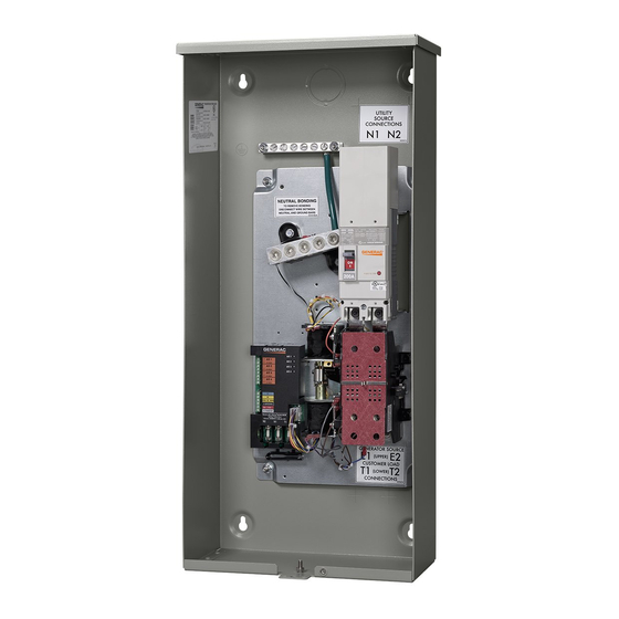
Automatic Transfer Switch
150 - 200 Amp, Ringless Meter Socket, Service Entrance Rated
Integrated Meter Transfer Switch
RXUW200A3 – 200A
RXUW200A3LV – 200A with Lever Bypass
RXUW150A3 – 150A
RXUW150A3LV – 150A with Lever Bypass
Upgradeable Integrated Meter Transfer Switch
RBU200A3 – 200A
RBU200A3LV – 200A with Lever Bypass
RBU150A3 – 150A
RBU150A3LV – 150A with Lever Bypass
G0074000 – RBU Transfer Switch Upgrade Kit
SERIAL NUMBER: _________________________
DATE PURCHASED:________________________
WWW.GENERAC.COM
http://www.generac.com/service-support/product-support-lookup
For
Model Number
888-436-3722
®
Advertisement
Table of Contents

Related Manuals for Generac Power Systems RXUW200A3


Summary of Contents for Generac Power Systems RXUW200A3
- Page 1 Automatic Transfer Switch 150 - 200 Amp, Ringless Meter Socket, Service Entrance Rated Model Number Integrated Meter Transfer Switch RXUW200A3 – 200A RXUW200A3LV – 200A with Lever Bypass RXUW150A3 – 150A RXUW150A3LV – 150A with Lever Bypass Upgradeable Integrated Meter Transfer Switch RBU200A3 –...
- Page 2 WARNING CANCER AND REPRODUCTIVE HARM www.P65Warnings.ca.gov. (000393a) Automatic Transfer Switch Owner’s Manual...
-
Page 3: Table Of Contents
Table of Contents Section 1: Safety Section 4: Operation (RXUW Models Only) Introduction ............1 Functional Tests and Adjustments ....17 Read This Manual Thoroughly ........1 Manual Operation ..........17 Safety Rules ............1 Close to Utility Source Side ........17 Close to Generator Source Side .......18 Electrical Hazards ..........2 Return to Utility Source Side ........18 General Hazards ..........3... - Page 4 This page intentionally left blank. Automatic Transfer Switch Owner’s Manual...
-
Page 5: Section 1: Safety
Safety Section 1: Safety Introduction WARNING Thank you for purchasing a Generac Power Systems Inc. product. This unit has been designed to provide high Indicates a hazardous situation which, if not avoided, performance, efficient operation, and years of use when could result in death or serious injury. -
Page 6: Electrical Hazards
Safety Electrical Hazards DANGER DANGER Electrocution. High voltage is present at Equipment malfunction. Installing a dirty or damaged transfer switch and terminals. Contact with live transfer switch will cause equipment malfunction and terminals will result in death or serious injury. will result in death or serious injury. -
Page 7: General Hazards
Safety General Hazards DANGER DANGER Electrocution. In the event of electrical accident, Electrical backfeed. Use only approved switchgear to immediately shut power OFF. Use non-conductive isolate generator from the normal power source. implements to free victim from live conductor. Apply Failure to do so will result in death, serious injury, first aid and get medical help. - Page 8 Safety This page intentionally left blank. Automatic Transfer Switch Owner’s Manual...
-
Page 9: Section 2: General Information
General Information Section 2: General Information Unpacking The conductor size range of the 4 Jaw Meter Socket is as follows: Carefully unpack the transfer switch. Inspect closely for any damage that might have occurred during shipment. Switch Conductor Wire Range The purchaser must file with the carrier any claims for Rating Tightening Torque... -
Page 10: Utility Service Circuit Breaker
General Information Safe Use of Transfer Switch Utility Service Circuit Breaker The utility service circuit breakers for 150/200 amp WARNING models are: Consult Manual. Read and understand manual • Type 225AF, 2-pole completely before using product. Failure to • 22,000 A/C completely understand manual and product •... -
Page 11: Application Considerations
General Information Application Considerations Figure 2-2. The SACM has a test button (C) used to simulate an overload condition. This button operates Generator overload condition is determined by generator even when the transfer signal is inactive. The Generator frequency. Loads are shed when frequency is less than Control Wiring is connected to terminals (D). -
Page 12: Accessories
General Information Accessories Accessory Description G0074000 Includes all pieces to perform conversion of a RBU Meter Main into a RXUW Transfer Switch. RBU Transfer Switch Upgrade Kit G0074010 Replacement outer top cover and sealing ring for ring style meter retainment. Ring Style Meter Cover Verify you have the proper type to meet local code requirements. -
Page 13: Section 3: Installation
Installation Section 3: Installation Introduction to Installation Open Enclosure This equipment has been wired and tested at the factory. Figure 3-1. First, remove outer top cover (A): Installing the switch includes the following procedures: 1. Rotate latch (B) clockwise until clear of latch hole. •... -
Page 14: Connecting Power Source (Rbu And Rxuw)
Installation 010088 Figure 3-3. Remove Bottom Cover and Panel Connecting Power Source (RBU and terminals are bonded to each other with a jumper wire (A). RXUW) 4. If applicable, connect Solar directly to Utility at S1 DANGER and S2 with Lugs provided on bus under circuit breaker cover as local codes permit. -
Page 15: Connecting Alternate Power Source (Rxuw Only)
Installation Connecting Alternate Power Source (RXUW Only) 1. See Figure 3-4. Connect generator to the generator terminals (E1 and E2) on the transfer mechanism. 2. Connect the generator neutral wire to the lower neutral lug. IMPORTANT NOTE: A jumper wire (B) bonds the upper and lower Neutral lugs. - Page 16 Installation Thermostat 1 Air Conditioner 1 Thermostat 2 Air Conditioner 2 Thermostat 3 Air Conditioner 3 Thermostat 4 Air Conditioner 4 0 DC GROUND T1 (fused) 194 +12 VDC Battery Charge 23 TRANSFER N1 (fused) ® ® Utility Sense N2 (fused) Utility Sense 0 DC Ground...
-
Page 17: Connecting Start Circuit Wires
Installation Connecting Start Circuit Wires Connecting SACM Control system interconnections consist of N1, N2, and Figure 3-5. The SACM can control an air conditioner T1, and leads 23, 0, and 194 (see Figure 3-5). (24 VAC) directly. NOTE: Generac Type TC-ER-JP power and control tray cable can be installed as permitted by the 2017 NEC. -
Page 18: Auxiliary Contact
Installation Auxiliary Contact Fault Current Label Figure 3-6. If desired, there is one normally-closed Figure 3-7. A Fault Current Identification Label is Auxiliary Contact (A) on the transfer switch to operate provided in the bag containing the unit Owner’s Manual and customer accessories, remote advisory lights, or remote transfer switch manual operating handle. -
Page 19: Install Transfer Switch And Sacm Kit (Rbu Only)
Installation Install Transfer Switch and SACM Kit (RBU Only) 1. See Figure 3-8. Remove screws (A) from bus bar assembly and set aside. 2. Remove screws (B) from bus bar assembly and remove assembly from sub panel. 010496 Figure 3-9. Install Kit G0074000 010495 Figure 3-8. - Page 20 Installation This page intentionally left blank. Automatic Transfer Switch Owner’s Manual...
-
Page 21: Section 4: Operation (Rxuw Models Only)
Operation (RXUW Models Only) Section 4: Operation (RXUW Models Only) Functional Tests and Adjustments CAUTION Following transfer switch installation and interconnection, inspect the entire installation carefully. A competent, Equipment damage. Do not use excessive force while qualified electrician should inspect it. The installation manually operating the transfer switch. -
Page 22: Close To Generator Source Side
Operation (RXUW Models Only) Close to Generator Source Side Generator Voltage Checks Before proceeding, verify the position of the switch by 1. On the generator panel, select MANUAL. The observing the position of the manual operation handle in generator should crank and start. Figure 4-1. -
Page 23: Checking Automatic Operation
Operation (RXUW Models Only) 5. Set the generator main circuit breaker to ON or its entire automatic sequence of operation. CLOSED. The generator now powers all LOAD NOTE: Timer durations may differ between generators circuits. Check generator operation under load as and settings. -
Page 24: Preparing For Maintenance
Operation (RXUW Models Only) 2. Verify generator MLCB (generator disconnect) is 8. After another 15 seconds, verify A/C 4 is energized OFF (OPEN). and Status LED A/C 4 is ON. 3. Set generator to AUTO mode at the controller. SACM Fuse Service 4. -
Page 25: Section 5: Drawings And Diagrams
Drawings and Diagrams Section 5: Drawings and Diagrams Installation Drawings No. A0000258227-A: 150-200A SER METER MAIN Automatic Transfer Switch Owner’s Manual... -
Page 26: Interconnection Drawings
Drawings and Diagrams Interconnection Drawings No. A0000258228-A (Part 1 of 2)—Liquid-Cooled Generator Automatic Transfer Switch Owner’s Manual... -
Page 27: No. A0000258228-A (Part 2 Of 2)-Air-Cooled Generator
Drawings and Diagrams No. A0000258228-A (Part 2 of 2)—Air-Cooled Generator Automatic Transfer Switch Owner’s Manual... - Page 28 Drawings and Diagrams This page intentionally left blank. Automatic Transfer Switch Owner’s Manual...
- Page 29 Drawings and Diagrams This page intentionally left blank. Automatic Transfer Switch Owner’s Manual...
- Page 30 Drawings and Diagrams This page intentionally left blank. Automatic Transfer Switch Owner’s Manual...
- Page 32 ® Part No. A0000243082 Rev. B 04/17/2020 ©2020 Generac Power Systems, Inc. Generac Power Systems, Inc. All rights reserved. S45 W29290 Hwy. 59 Specifications are subject to change without notice. Waukesha, WI 53189 No reproduction allowed in any form without prior written consent 1-888-GENERAC (1-888-436-3722) from Generac Power Systems, Inc.
Need help?
Do you have a question about the RXUW200A3 and is the answer not in the manual?
Questions and answers