Table of Contents
Advertisement
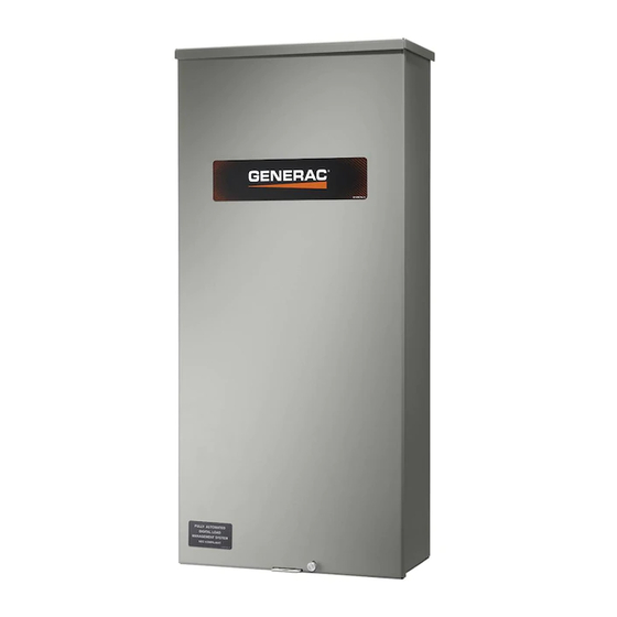
200 Amp, Single Phase, 240 VAC, Service Rated, 20–40 Circuit Load Center With Pass-Through Lugs
http://www.generac.com/service-support/product-support-lookup
Para español , visita:
Pour le français, visiter :
SAVE THIS MANUAL FOR FUTURE REFERENCE
Owner's Manual
Automatic Transfer Switch
SERIAL NUMBER: _________________________
DATE PURCHASED:________________________
WWW.GENERAC.COM
http://www.generac.com/service-support/product-support-lookup
For
Model Number
RXGW20SHA3
888-436-3722
003722
Advertisement
Table of Contents

Related Manuals for Generac Power Systems RXGW20SHA3


Summary of Contents for Generac Power Systems RXGW20SHA3
- Page 1 Owner’s Manual Automatic Transfer Switch 200 Amp, Single Phase, 240 VAC, Service Rated, 20–40 Circuit Load Center With Pass-Through Lugs Model Number RXGW20SHA3 003722 SERIAL NUMBER: _________________________ DATE PURCHASED:________________________ WWW.GENERAC.COM 888-436-3722 http://www.generac.com/service-support/product-support-lookup Para español , visita: http://www.generac.com/service-support/product-support-lookup Pour le français, visiter :...
- Page 2 WARNING CANCER AND REPRODUCTIVE HARM www.P65Warnings.ca.gov. (000393a) Automatic Transfer Switch Owner’s Manual...
-
Page 3: Table Of Contents
Table of Contents Section 1: Safety Rules & General Section 4: Drawings and Diagrams Information Installation Drawing .......... 15 Introduction ............1 No. 10000047450 ............15 Read This Manual Thoroughly ........1 Interconnection Drawing ........16 Safety Rules ............1 No. 10000047283—Page 1 of 4 (Liquid-Cooled Engine Generator) ......16 General Hazards ..........1 No. - Page 4 This page intentionally left blank. Automatic Transfer Switch Owner’s Manual...
-
Page 5: Section 1: Safety Rules & General Information
Section 1: Safety Rules & General Information Introduction DANGER Thank you for purchasing a Generac Power Systems Inc. product. This unit has been designed to provide high Indicates a hazardous situation which, if not avoided, performance, efficient operation, and years of use when will result in death or serious injury. -
Page 6: Electrical Hazards
Safety Rules & General Information Electrical Hazards DANGER DANGER Automatic start-up. Disconnect utility power and render unit inoperable before working on unit. Electrocution. High voltage is present at Failure to do so will result in death or serious injury. transfer switch and terminals. Contact with (000191) live terminals will result in death or serious injury. - Page 7 Safety Rules & General Information DANGER Equipment malfunction. Installing a dirty or damaged transfer switch will cause equipment malfunction and will result in death or serious injury. (000119) WARNING Electric shock. Only a trained and licensed electrician should perform wiring and connections to unit. Failure to follow proper installation requirements could result in death, serious injury, and equipment or property damage.
- Page 8 Safety Rules & General Information This page intentionally left blank. Automatic Transfer Switch Owner’s Manual...
-
Page 9: Section 2: Installation
Installation Section 2: Installation Introduction to Installation Install transfer switch as close as possible to electrical loads that will be connected to it. Mount transfer switch This equipment has been wired and tested at the factory. vertically to a rigid supporting structure. Level all mount- Installing the transfer switch includes the following proce- ing points to prevent transfer switch distortion. -
Page 10: Installing Breakers
Installation Installing Breakers Connecting Power Source and Generator Power Supply Figure 2-2. Insert tab on each breaker (A) into the hook on the bus (B). Push breaker into bus until it snaps into place. DANGER Electrocution. Turn utility and emergency power supplies to OFF before connecting power source and load lines. -
Page 11: Connecting Start Circuit Wires
Installation All power cables can enter enclosure through provided knockouts. Additional knockouts into transfer switch can be made in the field as needed. Conduit entry shall main- tain correct wire bending spaces required by Tables 312.6 (A) and (B) in the NEC. Conduits should be arranged to provide separation between utility and gener- ator supply conductors inside the enclosure. -
Page 12: Connecting Sacm
Installation Connecting SACM Figure 2-4. The SACM can control an air conditioner (24 VAC) directly. Control of Air Conditioner Load 1. Route thermostat cable (from furnace/thermostat to 3. If required, connect additional air conditioners to outdoor air conditioner unit) to transfer switch. the terminal strip terminals (A/C 2-4). -
Page 13: Auxiliary Contact
Installation Auxiliary Contact Fault Current Identification Label Figure 2-6. A Fault Current Identification Label is CAUTION provided in the bag containing the unit owner’s manual and transfer switch manual operating handle. The 2017 Equipment damage. Exceeding rated voltage and NEC requires the short-circuit current rating of the trans- current will damage the auxiliary contacts. - Page 14 Installation This page intentionally left blank. Automatic Transfer Switch Owner’s Manual...
-
Page 15: Section 3: Operation
Operation Section 3: Operation Functional Tests and Adjustments • Manual operation handle in UP position— LOAD terminals (T1, T2) are connected to util- ity terminals (N1, N2). CAUTION • Manual operation handle in DOWN position– LOAD terminals (T1, T2) are connected to Equipment damage. -
Page 16: Close To Generator Source Side
Operation Close to Generator Source Side Generator Voltage Checks Before proceeding, verify position of transfer switch by DANGER observing the position of the manual operation handle in Figure 3-1. If manual operation handle is DOWN, con- Electrocution. High voltage is present at tacts are closed in generator (standby) position. -
Page 17: Checking Automatic Operation
Operation 5. Set generator MLCB to ON (CLOSED). Generator With generator running and loads powered by generator now powers all LOAD circuits. Verify generator AC output, set transfer switch utility service disconnect operation under load as follows: circuit breaker to ON (CLOSED). The following will occur: •... -
Page 18: Shutting Generator Down To Perform Maintenance
Operation Shutting Generator Down To Perform Fuse Removal and Installation Maintenance Figure 3-2. A fuse removal and installation tool (A) is included in the control housing. Proceed as follows to shut down generator for mainte- nance: 1. Press OFF button on controller. 10000004183 Rev. -
Page 19: Section 4: Drawings And Diagrams
Drawings and Diagrams Section 4: Drawings and Diagrams Installation Drawing No. 10000047450 Automatic Transfer Switch Owner’s Manual... -
Page 20: Interconnection Drawing
Drawings and Diagrams Interconnection Drawing No. 10000047283—Page 1 of 4 (Liquid-Cooled Engine Generator) Automatic Transfer Switch Owner’s Manual... -
Page 21: No. 10000047283-Page 2 Of 4 (Liquid-Cooled Engine Generator)
Drawings and Diagrams No. 10000047283—Page 2 of 4 (Liquid-Cooled Engine Generator) Automatic Transfer Switch Owner’s Manual... -
Page 22: No. 10000047283-Page 3 Of 4 (Air-Cooled Engine Generator)
Drawings and Diagrams No. 10000047283—Page 3 of 4 (Air-Cooled Engine Generator) Automatic Transfer Switch Owner’s Manual... -
Page 23: No. 10000047283-Page 4 Of 4 (Air-Cooled Engine Generator)
Drawings and Diagrams No. 10000047283—Page 4 of 4 (Air-Cooled Engine Generator) Automatic Transfer Switch Owner’s Manual... - Page 24 Drawings and Diagrams This page intentionally left blank. Automatic Transfer Switch Owner’s Manual...
- Page 25 Drawings and Diagrams This page intentionally left blank. Automatic Transfer Switch Owner’s Manual...
- Page 26 Drawings and Diagrams This page intentionally left blank. Automatic Transfer Switch Owner’s Manual...
- Page 28 ©2019 Generac Power Systems, Inc. Generac Power Systems, Inc. All rights reserved. S45 W29290 Hwy. 59 Specifications are subject to change without notice. Waukesha, WI 53189 No reproduction allowed in any form without prior written 1-888-GENERAC (1-888-436-3722) consent from Generac Power Systems, Inc. www.generac.com...
Need help?
Do you have a question about the RXGW20SHA3 and is the answer not in the manual?
Questions and answers