
Subscribe to Our Youtube Channel
Related Manuals for RKI Instruments 72-RA-C


Summary of Contents for RKI Instruments 72-RA-C
- Page 1 GX-3R Operator’s Manual Part Number: 71-0477 Revision: P16 Released: 12/27/21 www.rkiinstruments.com...
- Page 2 WARNING Read and understand this instruction manual before operating instrument. Improper use of the gas monitor could result in bodily harm or death. Maintenance of the gas monitor is essential for proper operation and correct readings. Bump test the instrument before each day’s use with a known concentration of each target gas.
-
Page 3: Table Of Contents
Table of Contents Chapter 1: Introduction ..........7 Overview . - Page 4 -Compensated CO Detection ........27 Interference Information .
- Page 5 Replacing the Buzzer Cover ..........85 Replacing the Sensor Filters .
- Page 6 Appendix C: Interference Information ......118 ESR-A13i-H2S, H S Detection ......... . . 118 ESR-A13P-CO, CO Detection .
-
Page 7: Chapter 1: Introduction
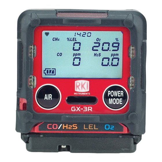
Chapter 1: Introduction Overview This chapter briefly describes the GX-3R gas monitor. This chapter also describes the GX-3R Operator’s Manual (this document). Table at the end of this chapter lists the specifications for the GX-3R. About the GX-3R Using an advanced detection system consisting of up to three gas sensors, the GX-3R personal four-gas monitor detects the presence of combustible gas, oxygen (O ), carbon monoxide (CO), and hydrogen sulfide (H... -
Page 8: Specifications
± 20% of reading * The GX-3R is also available set up for general hydrocarbons and calibrated to a combustible gas other than methane, such as isobutane. Con- sult RKI Instruments, Inc. for further information. Table 2: GX-3R Specifications Sampling... - Page 9 Table 2: GX-3R Specifications Safety/ • ATEX: Certificate Number: DEKRA 17ATEX0103 X Regulatory II1G Ex da ia IIC T4 Ga/IM1 Ex da ia I Ma (with NCR-6309) II1G Ex ia IIC T4 Ga/IM1 Ex ia I Ma (without NCR-6309) • IECEx: Certificate Number: IECEx DEK 17.0050X Ex da ia IIC T4 Ga/Ex da ia I Ma (with NCR-6309) Ex ia IIC T4 Ga/Ex ia I Ma (without NCR-6309) •...
-
Page 10: About This Manual
About this Manual The GX-3R Operator’s Manual uses the following conventions for notes, cautions, and warnings. NOTE: Describes additional or critical information. CAUTION: Describes potential damage to equipment. WARNING: Describes potential danger that can result in injury or death. 10 • Chapter 1: Introduction GX-3R Operator’s Manual... -
Page 11: Chapter 2: Description
Chapter 2: Description Overview This chapter describes the GX-3R instrument and its accessories. Instrument Description LEDs Charging Socket Threaded Inserts POW ER MODE GX-3R CO/H Buzzer Sensor Bottom Opening Retainer Cover Front Back Figure 1: Component Location Case The GX-3R’s sturdy, high-impact plastic case is radio frequency (RF) resistant and is suitable for use in many environmental conditions, indoors and out. -
Page 12: Control Buttons
Control Buttons Two control buttons, AIR and POWER MODE, are located below the LCD. Table 3: GX-3R Control Button Functions Button Function(s) • turns on LCD backlight • resets alarm condition if LATCHING is set to ON in Maintenance Mode •... -
Page 13: Sensors
Sensors The GX-3R uses three sensors to monitor combustible gas, oxygen (O ), carbon monoxide (CO), and hydrogen sulfide (H S) simultaneously. The sensors are located inside the GX-3R and are held in their sockets by the sensor retainer and bottom cover. The sensors use different detection principles, as described below. -
Page 14: Infrared Communications Port
CO/H S Sensor Dual Filter (Black and White) A dual filter is placed into a recess in the filter gasket over the dual CO/H S sensor. The black half is a charcoal filter for the CO sensor. The white half is a humidity filter for the H sensor. -
Page 15: Included Accessories
NOTE: Use of batteries or battery chargers not specified by RKI Instruments, Inc. will compromise the CSA classification and may void the warranty. See “Recharging the Batteries” on page 83. WARNING: To prevent ignition of a hazardous atmosphere, batteries must only be changed or charged in an area known to be nonhazardous. -
Page 16: Single-Unit Ac Charger
Single-Unit AC Charger The charging cable is a 4 foot cable with an AC adapter on one end and a charging plug that connects to the GX-3R on the other end. Charging Plug AC Adapter Figure 3: Charging Cable Calibration Cup Use the calibration cup to apply gas during a bump test, calibration, or gas test. -
Page 17: Belt Clip
Belt Clip A belt clip makes it easy to hook the GX-3R to a utility belt. Belt Clip Figure 5: Belt Clip SDM-3R The SDM-3R is a calibration station for the GX-3R and GX-3R Pro. The station’s buttons can be used for operations (Standalone Mode) or a computer can be used to control the docking station (PC Controlled Mode). -
Page 18: Chapter 3: Operation
Chapter 3: Operation Overview This chapter explains how to use the GX-3R to perform confined space entry monitoring or general area monitoring in Measuring Mode. Start Up This section explains how to start up the GX-3R, get it ready for operation, and turn it off. WARNING: A thin protective film covers the display to prevent scratches during shipping. - Page 19 If CAL RMDR is set to ON (factory setting) and a calibration is due, the screen that appears next depends on how CAL EXPD is set in User Mode (see “CAL EXPD” on page 67). The three possible screens are described below. If a calibration is not due, the instrument shows how many days are left until a calibration is due.
- Page 20 If BUMP.RMDR is set to ON (factory setting is OFF) and a bump test is due, the screen that appears next depends on how BUMP.EXPD is set in User Mode (see “BUMP.EXPD” on page 71). The three possible screens are described below. If a bump test is not due, the instrument shows how many days are left until a bump test is due.
- Page 21 The Battery Voltage Screen appears for a few seconds. An “AL-L” at the bottom of the screen indicates that the alarms are set to latching. An “AL-A” at the bottom of the screen indicates that the alarms are set to auto reset. See pg.103 for a description of how to change this parameter.
- Page 22 If ID DISP is set to ON (factory setting is OFF, see pg.104), the User ID Screen appears for a few seconds, followed by the Station ID Screen. 7:49 7:49 USEr Id Stn Id U_ID_001 S_ID_001 If the GX-3R experiences a sensor failure during start up, the display shows which sensor failed and the buzzer sounds a double pulsing tone once per second.
- Page 23 If Password Protection is turned On (factory setting is Off) using the SDM-3R PC program, a user-set password is required to perform an auto zero. When the password screen appears, adjust each digit with the AIR button and press and release the POWER MODE button to move on to the next digit.
-
Page 24: Performing A Demand Zero
Performing a Demand Zero Perform a demand zero before using the GX-3R. This sets the combustible gas, H S, and CO channels to zero and the OXY channel to 20.9%. Find a fresh-air environment. This is an environment free of toxic or combustible gases and of normal oxygen content (20.9%). -
Page 25: Measuring Mode Operation
Measuring Mode Operation When the GX-3R completes its startup sequence, it is in Measuring Mode. In Measuring Mode the GX-3R continuously monitors the sampled atmosphere and displays the target gas concentrations. The GX-3R is considered to be in Normal Operation if there are no alarm indications. -
Page 26: Combustible Gas Detection
If you suspect that the GX-3R is not operating correctly: a. Take the GX-3R to a fresh air environment and perform a demand zero as described on pg.24. b. Perform a bump test as described on pg.49. Combustible Gas Detection There are three issues to keep in mind when monitoring for combustible gas. -
Page 27: Oxygen-Enriched Atmospheres
Overscale Protection The GX-3R protects the combustible gas sensor by temporarily turning off the sensor power if levels exceeding 100% LEL are detected. Nevertheless, combustible gas concentrations above 100% LEL can still affect the zero level or calibration of the combustible gas sensor. CAUTION: Do not expose the combustible gas sensor to high concentrations of combustible gas such as that from a butane lighter. -
Page 28: Interference Information
Interference Information Some gases interfere with CO and H S sensors. For a complete list of these gases, see pg.118. Aspirator Adapter Sampling The aspirator adapter accessory is used when it is necessary to draw sample from an area that cannot be entered or that must be checked for safety before entry, such as a tank or confined space. -
Page 29: Alarms
Monitor the readings and note if any alarms occur. The readings will peak shortly after the last squeeze and may decrease before all the channels can be checked. Use the Peak screen in Display Mode to see the maximum readings for each channel (see pg.37). NOTE: The peak readings for each channel are saved until a higher peak is recorded, the peak readings are reset, or the instrument is turned off. - Page 30 Table 5: Alarm Types and Indications Alarm Type Visual Indications Other Indications Alarm H • Affected channel’s gas reading, gas • High-low tone sounding name, and units flash twice per second Concentration of gas rises above • ALARM H appears at the bottom of •...
-
Page 31: Responding To Alarms
Table 5: Alarm Types and Indications Alarm Type Visual Indications Other Indications Sensor Failure • SENSOR appears at the bottom of Double pulsing tone once per the screen and the failed sensor(s) are second indicated with FAIL under the gas name. - Page 32 Responding to an H2 RICH Alarm (H -Compensated CO Sensor Only) The H2 RICH alarm automatically clears once the hydrogen level decreases below 2000 ppm (parts per million). Responding to Over Range Alarms WARNING: An over range condition may indicate an extreme combustible gas, toxic gas, or oxygen concentration.
- Page 33 Responding to Battery Alarms WARNING: The GX-3R is not operational as a gas monitoring device during a dead battery alarm. Take the Model GX-3R to a non-hazardous area and replace or recharge the batteries as described in “Recharging the Batteries” on page 83.
- Page 34 Attempt to set the date using the DATE menu item in User Mode. See pg.79. If the date cannot be set correctly, contact RKI Instruments, Inc. as soon as possible. Responding to System Failure Alarms...
-
Page 35: Data Logging
GX-3R. The GX-3R Data Logger Management Program is available at www.rkiinstruments.com/gx3r. The USB/IrDA adapter cable is available from RKI Instruments, Inc. The data logging capacity depends on how often the GX-3R stores data, how many channels are active, and how often the GX-3R is turned on and off. -
Page 36: Chapter 4: Display Mode
Chapter 4: Display Mode This section describes Display Mode which is accessible from Measuring Mode. See Table 8 below for a list of Display Mode’s menu items, a short description of each item, and the page number for further description. Table 8: Display Mode Menu Items Display Mode Menu Description... -
Page 37: Tips For Using Display Mode
Tips for Using Display Mode • To enter Display Mode and scroll from one menu item to the next or skip an item when a question is asked, press and release POWER MODE. • To enter an item, press and release AIR. •... -
Page 38: Stel Screen (Stel)
STEL Screen (STEL) The STEL Screen displays the short term exposure limit (STEL) readings for H S and CO only. The STEL reading is the average reading over the last 15 minutes. 7:49 STEL TWA Screen (TWA) The TWA Screen displays the time weighted average (TWA) readings for H S and CO only. - Page 39 Available Converted Target Gases Available Converted Based on Calibrated Target Gas Target Gases During (Selected in Gas Select Mode) HC GAS LIST i-C4H10 LIMITED Status CH4 (methane) (isobutane) CH4 (methane) i-C4H10 (isobutane) H2 (hydrogen) CH3OH (methanol) C2H2 (acetylene) C2H4 (ethylene) C2H6 (ethane) C2H5OH (ethanol) C3H6 (propylene)
-
Page 40: Changing The User Id (User Id)
Press and release AIR to enter the screen. The current gas flashes at the bottom of the screen. 7:49 HC GAS SELECT Use AIR to scroll through the list of gases. When the desired gas is displayed, press and release POWER MODE. The changes are saved and the instrument returns to the LIST screen. -
Page 41: Changing The Station Id (Stn Id)
Changing the Station ID (STN ID) This screen only appears if DISP.SET in User Mode is set to ON (factory setting) and if ID DISP in Maintenance Mode is set to ON (factory setting is OFF). Use this screen to select a station ID from the 128 station IDs that are stored in the GX-3R’s memory. -
Page 42: Last Successful Calibration Date (Cal Data)
Last Successful Calibration Date (CAL DATA) The CAL DATA screen shows the date of each installed sensor’s last successful calibration. This screen only appears if CAL.RMDR is set to ON in User Mode. After entering Display Mode, press and release POWER MODE until CAL DATA appears. -
Page 43: Last Successful Bump Test Date (Bump Data)
Last Successful Bump Test Date (BUMP DATA) The BUMP DATA screen shows the date of each installed sensor’s last successful bump test. This screen only appears if BUMP.RMDR is set to ON. After entering Display Mode, press and release POWER MODE until BUMP DATA appears. -
Page 44: Viewing Alarm Settings Screen (Alarm--Pt)
Alarm Points Screen (ALARM--PT) The Alarm Points Screen shows the gas alarm settings for all active channels. After entering Display Mode, press and release POWER MODE until ALARM--PT appears. 7:49 dISP ALARM--PT Press and release AIR. The Full Scale Settings screen appears and shows full scale settings for each channel. -
Page 45: Chapter 5: User Mode And Calibration
Chapter 5: User Mode and Calibration Overview This section describes the GX-3R in User Mode. See Table 9 below for a list of the items found in User Mode, the page that the menu item’s instructions can be found on, and a short description of the menu item. - Page 46 Table 9: User Mode Menu Items User Mode Description Menu Item CAL SET (cont’d) CAL EXPD Defines what action must be taken if a calibration is due upon startup. (pg.67) CONFIRM (factory setting): Press and release AIR to acknowledge that calibration is due and continue to Measuring Mode.
- Page 47 Table 9: User Mode Menu Items User Mode Description Menu Item BEEP (pg.75) Set confirmation beep parameters. BEEP SEL LED: LEDs flash and instrument vibrates based on interval defined in (pg.75) BEEP INT to confirm instrument is still operating. BUZZER: Buzzer sounds and instrument vibrates based on interval defined in BEEP INT to confirm instrument is still operating.
-
Page 48: Entering User Mode
Table 9: User Mode Menu Items User Mode Description Menu Item ROM/SUM View the firmware information for the GX-3R’s sensor board and main board. (pg.80) START (pg.81) Press and release POWER MODE to begin the warmup sequence and enter Measuring Mode. -
Page 49: Tips For Using User Mode
at the top of the screen indicates that the GX-3R is in User Mode. Use AIR to move through the User Mode menu items. Tips for Using User Mode • To scroll from one menu item to the next, press and release AIR. To reverse the scrolling direction: a. - Page 50 Install the calibration cup onto the GX-3R. Use the label and imprinting to make sure that the calibration cup gets installed in the correct orientation relative to the GX-3R. Be sure the calibration cup is pushed on all the way. POW ER MO DE GX-3R...
- Page 51 For toxic gas cylinders (like cylinders containing H S), it is important to vent the regulator while installing it onto the cylinder. Venting the regulator during installation helps prevent air from getting into the cylinder and degrading the gas. Open the regulator by turning the knob counterclockwise and install it onto the cylinder.
- Page 52 12 . At the end of the countdown, the instrument analyzes the results. Follow the flow chart to determine the bump test outcome. Bump test passed? Multiple Cylinders AUTO CAL On? Assigned? (default is on) Auto start after successful bump Calibration passed? set to on? (default is on) Multiple Cylinders...
- Page 53 Option A from Flow Chart Option B from Flow Chart Option C from Flow Chart • Bump test passed • Bump test passed • Bump test passed • Multiple cylinders assigned • One cylinder assigned • One cylinder assigned • Auto Start After Successful Bump set to •...
- Page 54 Option D from Flow Chart Option E from Flow Chart Option F from Flow Chart • Bump test failed • Bump test failed • Bump test failed • A-CAL set to OFF (factory setting is • A-CAL set to ON (factory setting) •...
- Page 55 Option G from Flow Chart Option H from Flow Chart • Bump test failed • Bump test failed • A-CAL set to ON (factory setting) • A-CAL set to ON (factory setting) • Calibration passed • Calibration passed • One cylinder assigned •...
-
Page 56: Performing A Calibration (Gas Cal)
Performing a Calibration (GAS CAL) Calibration Notes • To fully calibrate the sensors, you must do a fresh air adjustment (AIR CAL) and a span adjustment (AUTO CAL). • Bump test the instrument before each day’s use with a known concentration of each target gas. - Page 57 If the fresh air adjustment fails, “FAIL AIR” displays. Press and release POWER MODE to acknowledge the failure. See “Troubleshooting” on page 82. Performing a Span Adjustment in AUTO CAL Preparing for a Span Adjustment To adjust the span on the GX-3R, you will need: •...
- Page 58 Performing a Span Adjustment While in User Mode, press AIR to scroll to GAS CAL. 7:49 GAS CAL Press and release POWER MODE. The AIR CAL menu item appears. Use AIR to scroll to the AUTO CAL menu item. 7:49 AUTO CAL Press and release POWER MODE.
- Page 59 10 . Allow the gas to flow for 1 minute. 11 . Press and release POWER MODE. 12 . Follow the flow chart to determine the calibration outcome. Calibration passed? Multiple Cylinders Assigned? Auto start after successful cal set to on? (default is on) *NOTE: Auto start after successful cal parameter set using Datalogging or SDM-3R PC Programs.
- Page 60 Option A from Flow Chart Option B from Flow Chart • Calibration passed • Calibration passed • Multiple cylinders assigned • One cylinder assigned • Auto Start After Successful Cal set to ON (factory setting) 1. The instrument indicates that all channels passed the 1.
- Page 61 Option C from Flow Chart Option D from Flow Chart • Calibration passed • Calibration failed • One cylinder assigned • Auto Start After Successful Cal set to OFF (factory setting is 1. The instrument indicates that all channels passed the 1.
- Page 62 Setting the Calibration Values in CAL--P While in User Mode, press AIR to scroll to GAS CAL. 7:49 GAS CAL Press and release POWER MODE. The AIR CAL menu item appears. Use AIR to scroll to the AUTO CAL menu item. 7:49 AUTO CAL Press and release POWER MODE.
- Page 63 Use AIR to scroll to the channel whose calibration gas value you want to change. 7:49 7:49 - - - %LEL - - - CAL--P CAL--P 7:49 7:49 - - - - - - CAL--P CAL--P 7:49 ESCAPE Press and release POWER MODE. The calibration value begins to flash. In the example below, the combustible gas channel is selected.
- Page 64 10 . Press and release POWER MODE to save the change. The calibration gas value stops flashing and the unit returns to the channel selection screen. 11 . Repeat Step 7 through Step 10 for any other channels that need to be changed. 12 .
- Page 65 Press and release POWER MODE. The combustible gas channel displays. 7:49 %LEL - - - CYL SEL Use AIR to scroll to the channel whose cylinder assignment you want to change. 7:49 7:49 - - - %LEL - - - CYL SEL CYL SEL 7:49...
-
Page 66: Setting Calibration Parameters (Cal Set)
14 . Press AIR to scroll to ESCAPE. 15 . Press and release POWER MODE. The instrument returns to the AUTO CAL menu item in the GAS CAL menu. 16 . See “Exiting the GAS CAL Menu” on page 66 to return to User Mode. Exiting the GAS CAL Menu While in the GAS CAL menu, press AIR to scroll to ESCAPE. - Page 67 CAL INT This setting defines the amount of time between calibrations. The time can be set in 1 day increments. The minimum setting is 1 day and the maximum setting is 1000 days. The factory setting is 90 days. After entering the CAL SET menu, press AIR to scroll to CAL INT. 7:49 CAL INT Press and release POWER MODE.
-
Page 68: Setting Bump Test Parameters (Bump Set)
See “Entering Measuring Mode (START)” on page 81 to enter Measuring Mode. Setting Bump Test Parameters (BUMP SET) The BUMP SET menu item has 5 items: SETTINGS, BUMP.RMDR, BUMP INT, BUMP.EXPD, and ESCAPE. While in User Mode, press AIR to scroll to BUMP SET. 7:49 BUMP SET Press and release POWER MODE. - Page 69 See “Exiting the SETTINGS Menu” on page 70 to return to the BUMP SET menu. See “Exiting the BUMP SET Menu” on page 71 to return to User Mode. CHECK CHECK is the bump test tolerance value and is represented as a percentage of the calibration gas concentration.
- Page 70 AUTO CAL ON (factory setting): If a bump test fails, the unit automatically begins a calibration. OFF: If a bump test fails, the unit does not automatically begin a calibration. After entering the BUMP SET\SETTINGS menu, press AIR to scroll to AUTO CAL. 7:49 AUTO CAL Press and release POWER MODE.
- Page 71 BUMP INT This setting defines the amount of time between bump tests. The time can be set in 1 day increments. The minimum setting is 0 days and the maximum setting is 30 days (factory setting). After entering the BUMP SET menu, press AIR to scroll to BUMP INT. 7:49 BUMP INT Press and release POWER MODE.
-
Page 72: Alarm Settings (Alarm--Pt)
Alarm Settings (ALARM--PT) The ALARM--PT menu item has 3 items: ALARM--PT, DEF--ALMP, and ESCAPE. While in User Mode, press AIR to scroll to ALARM--PT. 7:49 ALARM--PT Press and release POWER MODE. The first channel displays. 7:49 %LEL - - - ALARM--PT Setting the Alarm Points After entering the Alarm Points menu item, press AIR to scroll through to the instrument... - Page 73 The Warning setpoint for the channel flashes. In the example below, the CO channel is selected. 7:49 1200 7:49 ALARM H 7:49 WARNING For all settings: 1) AIR to adjust 2) POWER MODE to save and 7:49 continue STEL 7:49 ALARM Use AIR to adjust the Warning setpoint.
-
Page 74: Updating The Lunch Break Setting (Lunch)
Defaulting the Alarm Points Defaulting the alarm points defaults them back to factory settings as outlined in Table on page 8 or to the settings saved in the SAVE-AP menu item in Gas Select Mode if you have performed a SAVE-AP operation. After entering the Alarm Points menu item, press AIR to scroll to DEF-ALMP. -
Page 75: Setting The Confirmation Beep And Non-Compliance Indicator (Beep)
Setting the Confirmation Beep and Non-Compliance Indicator (BEEP) The BEEP menu item has 3 items: BEEP SEL, BEEP INT, and ESCAPE. While in User Mode, press AIR to scroll to BEEP. 7:49 BEEP Press and release POWER MODE. The BEEP SEL menu item appears. 7:49 BEEP SEL BEEP SEL... - Page 76 b. CAL EXPD is set to CONFIRM or NONE and a calibration is due (cleared by successful calibration). c. The instrument goes into any gas alarm (cleared by successful bump test or calibration). NOTE: Depending on the Need to get Bump Log setting (only accessed via SDM-3R program), a data download may also be needed to clear the gas alarm non- compliance.
-
Page 77: Updating The Backlight Time (Bl Time)
Updating the Backlight Time (BL TIME) This setting defines how long the LCD backlight stays on when you press any button. The minimum setting is OFF; the maximum setting is 255 seconds. The factory setting is 30 seconds. While in User Mode, press AIR to scroll to BL TIME. 7:49 BL TIME Press and release POWER MODE. -
Page 78: Display Mode Items (Disp Set)
Display Mode Items (DISP SET) OFF: LIST, USER ID, and STN ID items do not appear in Display Mode. ON (factory setting): LIST item appears in Display Mode. USER ID and STATION ID screens appear in Display Mode if ID DISP in Maintenance Mode is also set to ON (factory setting is OFF). -
Page 79: Setting The Date/Time (Date)
Setting the Date/Time (DATE) From the main menu, place the cursor next to DATE. 7:49 DATE Press and release POWER MODE. The date and time display with the year flashing. 7:49 18 - 12.20 7:49 Use AIR to display the desired year. Press and release POWER MODE to save the setting. -
Page 80: Viewing The Rom/Sum (Rom/Sum)
Press and release POWER MODE. The Set Password Screen appears. The current password appears and the first digit flashes. 7:49 0 4 0 5 PASSWORD Use AIR to display a number from 0 to 9. Press and release POWER MODE to enter the selection and advance to the next number. To go back a number, press and hold AIR and POWER MODE for a few seconds. -
Page 81: Entering Measuring Mode (Start)
Entering Measuring Mode (START) While in User Mode, press AIR to scroll to START. 7:49 START Press and release POWER MODE. The instrument begins its warmup sequence. GX-3R Operator’s Manual Chapter 5: User Mode and Calibration • 81... -
Page 82: Chapter 6: Maintenance
WARNING: RKI Instruments, Inc. recommends that service, calibration, and repair of RKI Instruments be performed by personnel properly trained for this work. Replacing sensors and other parts with original equipment does not affect the intrinsic safety of the instrument. -
Page 83: Instrument Cleaning
Instruments, Inc. for further instruction. • The sensor for the affected channel(s) may need replacement. • Heart symbol at the • A microprocessor error has • Contact RKI Instruments, Inc. for further top of the screen occurred. instruction. becomes steadily on or disappears •... - Page 84 Make sure the GX-3R is off. Plug the AC adapter into an electrical outlet. Plug the charging jack straight into the GX-3R’s charging socket from the top. When properly connected, a green LED turns on at the top of the GX-3R. Figure 11: Connecting the Charging Cable The LED at the top of the GX-3R turns orange while charging.
-
Page 85: Replacing The Buzzer Cover
Replacing the Buzzer Cover The buzzer cover may need to be replaced if it becomes saturated or clogged with particles. Remove the rubber boot from the GX-3R. Peel off the old buzzer cover located between the AIR and POWER MODE buttons. If necessary, clean any remaining residue from the case. - Page 86 S-Only Sensor Filter: A white humidity filter is installed over H S-only sensors. The filter absorbs humidity in the sampling environment to prevent unstable readings around 0 ppm S. For users with a 1 ppm H S alarm setpoint, the filter should be replaced if you notice: a drift on the H S channel’s zero reading, unexplained H S readings, the filter appears dirty, or...
-
Page 87: Replacing The Hydrophobic Dust Filter
Bottom Cover Filter Gasket/Hydrophobic Dust Filter Assembly, gasket tabs on opposite side of this view Toxic Sensor Filter, See Table Sensor Filter NOTE: All filters installed black-side-up. Toxic Sensor Filters Black Filter For CO-only M ater ial sensor W hite B lack Filter Filter... -
Page 88: Replacing A Sensor
Install the new filter gasket/hydrophobic dust filter assembly with the gasket tabs facing down. Bottom Cover Filter Gasket/Hydrophobic Dust Filter Assembly, gasket tabs on opposite side of this view Sensor Retainer Side View Top View Figure 15: Replacing the Hydrophobic Dust Filter Reattach the bottom cover to the GX-3R. - Page 89 Carefully insert the replacement sensor in the correct socket. Be sure that the new sensor is installed in the same position as the old sensor and that it is aligned correctly. The toxic and oxygen sensors have slots to orient the sensor. The combustible gas sensor has tabs to orient the sensor.
-
Page 90: Replacing The Battery Board
Replacing the Battery Board Replace the battery board when the GX-3R doesn’t hold a charge anymore. Verify that the GX-3R is off. Remove the rubber boot, if installed. Place the GX-3R LCD-side-down. Unscrew the 4 screws that hold the two case halves together. The alligator or belt clip does not need to be removed. - Page 91 Gently remove the battery board. A black rectangular gasket may come out with the battery board. Black Gasket Rear Case Battery Board Figure 19: Removing the Battery Board Place the black rectangular gasket flat in the rear case. 10 . Place the new battery board battery-side-down in the rear case. The case has protrusions that fit in holes on the battery board.
- Page 92 11 . Secure the battery board using the screws removed in Step 7. Figure 21: Reinstalling Battery Board Screws 12 . Be sure the gasket along the edge of the rear case is seated correctly. The flat side of the gasket faces away from the case.
-
Page 93: Chapter 7: Storage
Chapter 7: Storage and Disposal Storage • Store away from direct sunlight • Store in a location with normal temperature and humidity • Store in a location free of gases, solvents, and vapors • Store away from dust and dirt •... -
Page 94: Chapter 8: General Parts List
Chapter 8: General Parts List Table 14 lists part numbers for the GX-3R’s replacement parts and accessories. Table 14: General Parts List Part Number Description 06-1248RK-03 Calibration kit tubing, 3 foot length 10-1086 Screw with flat and lock washers, for alligator clip 10-1087 Screw, for bottom cover and for battery pack 13-0112RK... - Page 95 Table 14: General Parts List (cont.) Part Number Description 49-2021 Single-unit DC adapter, with 4 foot cable 57-2098 Replacement Li-ion battery with board 65-7004 Dummy sensor 71-0477 Operator’s Manual, GX-3R (this document) 71-0491 Operator’s Manual, GX-3R Datalogging Program 81-0000RK-51 Calibration cylinder, 200 ppm H in air, 34 liter steel 81-0090RK-01 Calibration cylinder, 3-gas (CH...
-
Page 96: Appendix A: Maintenance Mode
Appendix A: Maintenance Mode Overview This appendix describes the GX-3R in Maintenance Mode. The GX-3R is factory-set to suit most applications. Update settings in Maintenance Mode only if required for your specific application. Maintenance Mode items and their factory settings are listed in Table 15 below. Table 15: Maintenance Mode Menu Items Maintenance Mode... - Page 97 Table 15: Maintenance Mode Menu Items Maintenance Mode Description Menu Item DEM ZERO ON (factory setting): You can manually perform a fresh air adjust in Measuring Mode by (pg.103) pressing AIR. OFF: You cannot manually perform a fresh air adjust in Measuring Mode by pressing AIR.
-
Page 98: Entering Maintenance Mode
Entering Maintenance Mode WARNING: The GX-3R is not in operation as a gas detector while in Maintenance Mode. Take the GX-3R to a non-hazardous location and turn it off if it is on. Press and hold AIR, then press and hold POWER MODE. You will hear a beep after one second. -
Page 99: Tips For Using Maintenance Mode
Tips for Using Maintenance Mode • To scroll from one menu item to the next, press and release AIR. To reverse the scrolling direction: a. Press and hold AIR. b. Immediately press POWER/MODE and then release both buttons. c. The scrolling direction returns to the original direction when you exit and reenter a menu. - Page 100 Install the calibration cup onto the GX-3R. Use the label and imprinting to make sure that the calibration cup gets installed in the correct orientation relative to the GX-3R. Be sure the calibration cup is pushed on all the way. POW ER MO DE GX-3R...
-
Page 101: Sensor/Battery Replacement Date (Sen Date)
Unscrew the regulator from the calibration cylinder. Remove the calibration cup from the GX-3R. Store the calibration kit in a safe and convenient place. Press and release POWER MODE to return to the GAS TEST menu item in Maintenance Mode. 10 . -
Page 102: Performing A Bump Test (Bump)
Use AIR to scroll to the item whose replacement date you want to view or change. 7:49 7:49 19- 2.11 19- 2.11 7:49 7:49 19- 2.11 19- 2.11 BATTERY 7:49 7:49 19- 2.11 ESCAPE To change the replacement date: a. With the desired item displayed, press and release POWER MODE. b. -
Page 103: Setting Alarms To Latching Or Self-Resetting (Latching)
Setting Alarms to Latching or Self-Resetting (LATCHING) ON (factory setting): The GX-3R remains in alarm until the alarm condition passes and POWER MODE is pressed. OFF: The GX-3R automatically resets an alarm when the alarm condition passes. While in Maintenance Mode, press AIR to scroll to LATCHING. 7:49 LATCHING Press and release POWER MODE. -
Page 104: Turning The Auto Zero Function On/Off (Autozero)
Turning the Auto Zero Function On/Off (AUTOZERO) ON: The GX-3R asks if you want to perform a fresh air adjustment at the end of the startup sequence. OFF (factory setting): The GX-3R does not ask if you want to perform a fresh air adjustment at the end of the startup sequence. -
Page 105: Turning The Zero Suppression On/Off (Zero Sup)
Maintenance Mode. It is not normally necessary to have the zero follower menu item appear in User Mode. Contact RKI Instruments before turning this setting on. Setting the Date/Time (DATE) From the main menu, place the cursor next to DATE. -
Page 106: Turning The Password On/Off (Password)
Press and release POWER MODE. The date and time display with the year flashing. 7:49 18 - 12.20 7:49 Use AIR to display the desired year. Press and release POWER MODE to save the setting. The month setting flashes. Repeat Step 3 and Step 4 to enter the month, day, hours, and minutes settings. The date and time are saved and the instrument returns to the DATE menu item. -
Page 107: Viewing The Rom/Sum (Rom/Sum)
Viewing the ROM/SUM (ROM/SUM) The ROM/SUM screen shows the instrument’s firmware version and the firmware checksum. While in Maintenance Mode, press AIR to scroll to ROM/SUM. 7:49 ROM / SUM Press and release POWER MODE. The screen cycles through the main board’s ROM/ SUM, the sensor board’s ROM/SUM, and the gas list’s ROM/SUM. -
Page 108: Entering Measuring Mode (Start)
Press and release POWER MODE to continue. Press and release AIR to return to the M.DEFAULT menu item in Maintenance Mode. 7:49 7:49 7:49 M.DEFAULT YES / MODE / AIR Press and release POWER MODE to perform a default operation. The instrument asks if you are sure you want to perform a default operation. -
Page 109: Appendix B: Gas Select Mode
Appendix B: Gas Select Mode Overview This appendix describes the GX-3R in Gas Select Mode. The GX-3R is factory-set to suit most applications. Update settings in Gas Select Mode only if required for your specific application. A description of the Gas Select Mode items is shown in Table 16 below. Table 16: Gas Select Mode Menu Items Menu Item (Page # of Description... -
Page 110: Entering Gas Select Mode
Entering Gas Select Mode WARNING: The GX-3R is not in operation as a gas detector while in Gas Select Mode. Take the GX-3R to a non-hazardous location and turn it off if it is on. Press and hold AIR, then press and hold POWER MODE. You will hear a beep after one second. -
Page 111: Changing The Gas Combination (Gas Comb)
• To change a flashing parameter, press and release AIR. To reverse the direction of change (ie. from increasing to decreasing or vice versa): a. Press and hold AIR. b. Immediately press POWER MODE and then release both buttons. • To exit an entered menu item without saving a change, press and hold AIR and POWER MODE for a few seconds. - Page 112 Press AIR to scroll through to the instrument channel whose target gas you want to change. 7:49 %LEL - - - 7:49 GAS COMB - - - 7:49 GAS COMB - - - 7:49 GAS COMB 7:49 ESCAPE - - - GAS COMB Press and release POWER MODE.
- Page 113 Use AIR to change the target gas or turn the channel off. Table 17: Target Gas Options for Each Channel Channel Target Gas Options Combustible • CH4 (methane) • n-C6H14 (hexane) • i-C4H10 (isobutane) • C7H8 (toluene) • H2 (hydrogen) •...
-
Page 114: Saving The Alarm Points (Save-Ap)
Saving the Alarm Points (SAVE-AP) Performing a SAVE-AP operation saves the current alarm setpoints. Performing a DEF ALMP operation in the ALARM-PT User Mode menu item sets the instrument’s alarm points to those saved during the SAVE-AP operation (if performed). Performing a SAVE-AP operation has no effect on an M.DEFAULT in Maintenance Mode. -
Page 115: Stealth And Vibrator Settings (Stealth)
While in Gas Select Mode, press AIR to scroll to MAX SPAN. 7:49 MAX SPAN Press and release POWER MODE. The current setting flashes. Use AIR to display the desired setting. Press and release POWER MODE to save the setting and return to the MAX SPAN menu item. -
Page 116: Lel Definition (Chg Lel)
LEL Definition (CHG LEL) NOTE: If CH4_VOL is selected for the combustible gas sensor in the GAS COMB menu item, the CHG LEL setting has no effect on operation. The CHG LEL menu item defines what standard the instrument follows in determining the LEL (lower explosive limit) for the combustible channel’s target gas. -
Page 117: Exiting Gas Select Mode (Start)
Table 18: Lower Explosive Limit ppm Levels Standard (ppm) IEC (ppm) ISO (ppm) Methyl ethyl ketone (MEK) 18,000 15,000 15,000 Methyl methacrylate (MMA) 17,000 17,000 17,000* Dimethyl ether (DME) 30,000 27,000 27,000 Methyl isobutyl ketone (MIBK) 12,000 12,000 12,000* Tetrahydrofuran (THK) 20,000 15,000 15,000*... -
Page 118: Appendix C: Interference Information
Appendix C: Interference Information All interference response values shown in this appendix are approximate. Response may vary between sensors. ESR-A13i-H2S, H S Detection Table 19: Interference Chart for ESR-A13i-H2S, H S Detection Chemical Indication Concentration Formula Value Acetone C3H6O 0.54 vol% 0.0 ppm Acetylene C2H2... - Page 119 Table 19: Interference Chart for ESR-A13i-H2S, H S Detection Chemical Indication Concentration Formula Value Methyl Methacrylate C5H8O2 0.43 vol% 0.1 ppm n-Hexane n-C6H14 0.30 vol% 0.0 ppm Nitrogen Dioxide 5.0 ppm -0.4 ppm Nitrogen Monoxide 99.2 ppm 2.6 ppm Nonane n-C9H2O 0.18 vol% 0.0 ppm...
-
Page 120: Esr-A13P-Co, Co Detection
ESR-A13P-CO, CO Detection Table 20: Interference Chart for ESR-A13P-CO, CO Detection Chemical Indication Concentration Formula Value Acetone 5380 ppm 0 ppm Acetylene 99.6 ppm 50 ppm Ammonia 255 ppm 1 ppm Arsine 1.1 ppm 4 ppm Benzene 0.3 vol% -1 ppm Carbon Dioxide 100 vol% 8 ppm... - Page 121 Table 20: Interference Chart for ESR-A13P-CO, CO Detection Chemical Indication Concentration Formula Value Methyl Methacrylate 0.425 vol% 0 ppm n-Heptane 0.275 vol% -1 ppm n-Hexane 0.3 vol% 0 ppm Nitrogen Dioxide 50.5 ppm 1 ppm Nitrogen Monoxide 99.2 ppm 53 ppm Nonane 0.175 vol% 0 ppm...
-
Page 122: Esr-A1Cp-Coh, H 2 -Compensated Co Detection
ESR-A1CP-COH, H -Compensated CO Detection Table 21: Interference Chart for ESR-A1CP-COH, H -Compensated CO Detection Chemical Indication Concentration Formula Value Acetone 0.54 vol% 1 ppm Acetylene 100 ppm 109 ppm Ammonia 38.6 ppm 0 ppm Benzene 0.30 vol% 0 ppm Carbon Dioxide 20.0 vol% 0 ppm... - Page 123 Table 21: Interference Chart for ESR-A1CP-COH, H -Compensated CO Detection Chemical Indication Concentration Formula Value Nonane 0.18 vol% 0 ppm Ozone 0.48 ppm 0 ppm Phosphine 2.51 ppm 3 ppm Propane 0.49 vol% 0 ppm Propylene 0.50 vol% 78 ppm Sulfur Dioxide 25.0 ppm 1 ppm...
-
Page 124: Esr-A1Dp-Cohs, Co Detection
ESR-A1DP-COHS, CO Detection Table 22: Interference Chart for ESR-A1DP-COHS, CO Detection Chemical Indication Concentration Formula Value Acetone 0.538 vol% -1 ppm Acetylene 99.6 ppm 84 ppm Ammonia 255 ppm 2 ppm Arsine 1.1 ppm 4 ppm Benzene 0.3 vol% -1 ppm Carbon Dioxide 100 vol% 8 ppm... - Page 125 Table 22: Interference Chart for ESR-A1DP-COHS, CO Detection Chemical Indication Concentration Formula Value n-Heptane 0.275 vol% -1 ppm n-Hexane 0.3 vol% 0 ppm Nitrogen Dioxide 50.5 ppm 1 ppm Nitrogen Monoxide 99.2 ppm 38 ppm Nonane 0.175 vol% 0 ppm Ozone 1.8 ppm 0 ppm...
-
Page 126: Esr-A1Dp-Cohs, H 2 S Detection
ESR-A1DP-COHS, H S Detection Table 23: Interference Chart for ESR-A1DP-COHS, H S Detection Chemical Indication Concentration Formula Value Acetone COCH 0.538 vol% -0.1 ppm Acetylene 99.6 ppm -0.1 ppm Ammonia 250 ppm -0.1 ppm Arsine 1.1 ppm 0.5 ppm Benzene 0.3 vol% -0.1 ppm Carbon Dioxide... - Page 127 Table 23: Interference Chart for ESR-A1DP-COHS, H S Detection Chemical Indication Concentration Formula Value Methyl Methacrylate 0.425 vol% -0.1 ppm n-Heptane 0.275 vol% -0.1 ppm n-Hexane 0.3 vol% -0.1 ppm Nitrogen Dioxide 50.5 ppm -4.6 ppm Nitrogen Monoxide 99.2 ppm 6.0 ppm Nonane 0.175 vol%...
- Page 128 Warranty RKI Instruments, Inc. warrants the GX-3R sold by us to be free from defects in materials, workmanship, and performance for a period of three years from the date of shipment from RKI Instruments, Inc. This includes the instrument and the original sensors. Replacement parts are warranted for 1 year from the date of their shipment from RKI Instruments, Inc.
Need help?
Do you have a question about the 72-RA-C and is the answer not in the manual?
Questions and answers