Table of Contents
Advertisement
Quick Links
Advertisement
Table of Contents

Related Manuals for Pulsar 78199


Summary of Contents for Pulsar 78199
- Page 1 Forward FN455S Manual...
-
Page 2: Table Of Contents
Safety Measures External Power Supply Operation Operating Features Installing Digital Module on the Optical Device Installing Pulsar 5x30 Monocular on to the Digital Module Powering on and Image Setting IR Illuminator Installing the IR Illuminator Removing the IR Illuminator Status Bar... - Page 3 Display-Off Function SumLight™ Function Wireless Remote Control Descriptions of Controls Remote Control Activation Using the Weaver Rail Stream Vision 2 Firmware Update USB Connection Technical Inspection Technical Maintenance and Storage Troubleshooting Legal Compliances and Disclaimers...
-
Page 4: Specifications
Specifications FN455S Model FN455S 78199 Optical Characteristics Lens focus, mm Relative aperture, D/f Field-of-view (Horizontal), ° Field-of-view (Horizontal), m per 100 m Detection Range (animal 500/546.8 height 1.7 m), m/y Minimum Focusing Distance, Recommended daylight optics magnification, x Electronic Specifications ... - Page 5 External Power Supply Micro USB type B (5V) Max. Battery Pack Life at t = 22 °C (Wi-Fi off, IR off), Hour Degree of protection IP code IPX7 (IEC60529) Operating temperature, °C -25 - +50 Overall Dimensions (with battery and monocular), 273х136х77 / 10.75x5.35x3.03 mm/inch Weight (with battery and...
-
Page 7: Description
To get started, see the sections: Battery Charging Battery Installation Installing Digital Module on the Optical Device Installing Pulsar 5x30 Monocular on to the Digital Module Powering on and Image Setting... -
Page 8: Package Contents
Package Contents Digital module Pulsar 5x30 Monocular Carrying Case Wireless Remote Control IPS7 Battery Pack Battery Pack Charger Power Adapter USB Cable Quick Start Guide Lens-Cleaning Cloth Warranty Card Neck strap... -
Page 9: Features
Features 1280X720 HD sensor Enhanced night-time sensitivity Simple transformation of a daytime optical device into night device. Preserves the benefits of daytime optics in night-time conditions Comfortable use in a wide range of daytime optical magnifications Invisible long-range IR Illuminator SumLight™... -
Page 10: Components And Controls
Components and Controls 1. Lens cover 2. Eyepiece cover 3. Battery compartment cover 4. Battery locking lever 5. Battery pack 6. RIGHT button... - Page 11 7. M (MENU) button 8. LEFT button 9. ON/OFF button 10. Lens focus knob 11. IR illuminator cover 12. IR illuminator connector cap 13. Connector for installing IR illuminator 14. MicroUSB port 15. Weaver rail 16. Adapter cover* 17. Optical device lens 18.
-
Page 12: Button Operation
Button Operation Operation Button Power device on short press Power device off long press for 3 secs long press for less than 3 Turn display off secs Turn display on short press Turn on/off SumLight™ short press Turn on/off Wi-Fi long press VideoRecorder Button... - Page 13 Enter main menu long press Navigation short press downwards/counterclockwise Navigation upwards/clockwise short press Confirm value short press Exit submenu without long press confirming selection Exit main menu long press Quick Menu Button Enter quick menu short press Switch between quick menu short press options Increase value...
-
Page 14: Battery Charging
Battery Charging The device is supplied with a rechargeable IPS7 Lithium-ion Battery Pack which allows the attachment to be used for up to 9 hours. Charge the battery before first use. Charging Step 1. Install the battery into the charger 1. - Page 15 Step 2. Сheck the current battery level Upon installation, a green LED indicator (28) on the charger will start to glow and begin flashing: - once if the battery charge ranges from 0% to 50%. - twice if the battery charge ranges from 51% to 75%. - three times if the battery charge ranges from 76% to 100%.
-
Page 16: Battery Installation
Battery Installation 1. Lower the lever (4). 2. Remove the protective cover of the battery compartment (3). 3. Insert the battery(5) into the slot designed for it on the device body so that the element (D) is pointing downwards. 4. -
Page 17: Safety Measures
Safety Measures Do not use the charger if it has been modified or damaged. Do not leave a battery unattended during charging. Do not leave the battery in a charger connected to the mains after charging is complete. The battery should be charged at a temperature between 0° C and +45° C, otherwise the battery life will be significantly reduced. -
Page 18: External Power Supply
External Power Supply Show device diagram External power is supplied from an external source, such as a 5V Power Bank. 1. Attach the external power source to the USB connector(14) on the device. 2. The device will switch to operation from the external power supply, while the IPS7 battery will be gradually recharged. - Page 19 3. A battery icon will appear on the display showing charge level as a percentage. 4. If the device is connected to a computer, network adapter or power bank that does not conform to the BC1.0 battery charger standard, an IPS7 battery will not begin charging: the external power icon only will be displayed 5.
-
Page 20: Operating Features
Before using the attachment make sure you mount it according to the instructions in the Installing Digital Module on the Optical Device Installing Pulsar 5x30 Monocular on to the Digital Module sections. Power off the device after use. -
Page 21: Installing Digital Module On The Optical Device
Installing Digital Module on the Optical Device Show device diagram... - Page 22 1. Select the adapter (available separately) with the required diameter of insert depending on the outer diameter of the lens of your optical device (see the Table). 2. The designation 42mm / 50mm / 56mm in the title of the adapter refers to the optical diameter of the lens in the optical device.
- Page 23 7. Mount the adapter with the insert into the lens of the optical device (17). 8. Move the lever (22) from its initial OPEN position to the CLOSE position. 9. Ensure that the adapter fits snugly against the lens. 10. If there is any gap, do the following: Loosen the locking screw(20) with an Allen key (S=2mm).
- Page 24 45.5 45.5 46.5 46.5 Cover adapter FN 46.7-47.6 42mm 47.7-46.7 48.7-49.6 49.7-50.6 51.6 51.6 53.4 53.4 54.7-55.6 Cover adapter FN 55.7-56.6 50mm 56.7-57.6 57.7-58.6 58.7-59.6 59.7-60.6 60.7-61.6 61.7-62.6 Cover adapter FN 56mm 62.7-63.6 63.7-64.6 64.7-65.6 ...
-
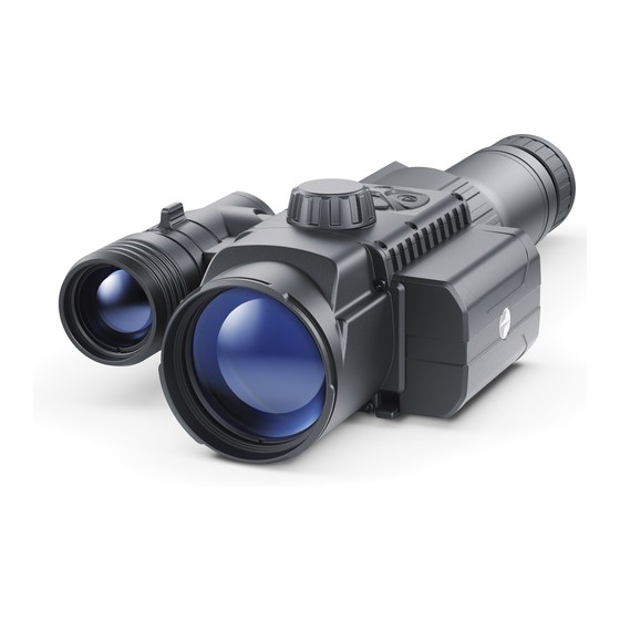
Page 25: Installing Pulsar 5X30 Monocular On To The Digital Module
Installing Pulsar 5x30 Monocular on to the Digital Module The Pulsar 5x30 monocular (included in the package) enables you to transform a digital module into a digital vision device for night-time observation with a magnification of 5x. 1. Insert the monocular tightly into the digital module as far as it will go... - Page 26 so that the pins on the monocular body (A) fit into the slots (B) of the digital module (see Fig.). 2. Turn the monocular anticlockwise so that the monocular is fixed onto the digital module. The triangular mark on the digital module and the square on the monocular body must be aligned.
-
Page 27: Powering On And Image Setting
Powering on and Image Setting Show device diagram 1. Remove the lens cap (1) by turning it anticlockwise. 2. Turn on the device with a short press of the ON/OFF (9) button. An image will appear on the display. 3. Adjust the resolution of the icons on the display by rotating the diopter... - Page 28 adjustment ring of your optical device. In future, it will not be necessary to rotate the eyepiece diopter adjustment ring, regardless of distance and other conditions. 4. Rotate the lens focus ring (10)to focus on the object being observed. 5. Basic settings (brightness and contrast adjustment) can be altered by using the quick menu.
-
Page 29: Installing The Ir Illuminator
Installing the IR Illuminator Show device diagram... - Page 30 Step 1. Install the IR illuminator 1. Remove the cap (12) from the connector to attach the IR illuminator (13). 2. Remove the cover(11) from the IR illuminator. 3. Install the IR illuminator on the connector (13). The lever(25) should be in the up position.
- Page 31 Step. 3. Adjust the power level of the IR illuminator 1. Briefly press the IR (24) button at the end of the illuminator. The power level when switching on is minimum 2. The IR illuminator icon will be displayed on the status bar with the relevant power level.
-
Page 32: Removing The Ir Illuminator
Removing the IR Illuminator 1. Raise the lever(25). 2. Disconnect the IR illuminator from the device. 3. Install the cap(12) on the connector for installing the IR illuminator (13) 4. Put the cover (11) on the IR illuminator. -
Page 33: Status Bar
Status Bar The status bar is at the bottom of the display and displays information on the actual operating status of the device, including: Auto shutdown function 1 min (if activated) Microphone IR illuminator power level (e.g. Level 3) Power Indication: - Battery Pack charge level (when the device is powered by the Battery Pack) - external battery power indicator (if the device is powered from an... -
Page 34: Quick Menu Functions
Quick Menu Functions Show device diagram 1. Enter the quick menu with a short press of theM (7) button. 2. A short press of the M (7) button enables you to switch between functions, as described below. - Page 35 Contrast – by pressing the RIGHT (6) and LEFT (8) buttons and changing the display contrast value from 0 to 20. Brightness – by pressing theRIGHT (6) andLEFT (8) buttons and changing the display brightness value from 0 to 20.
-
Page 36: Enter The Main Menu
Enter the Main Menu Show device diagram 1. Enter the main menu with a long press of the M (7) button. 2. Press the RIGHT (6) and LEFT (8) buttons to toggle through the main menu functions. 3. Open sub-items in the main menu with one short press of the M (7) button. - Page 37 button. 5. Automatic exit from the main menu occurs after 10 seconds of inactivity. General View of the Menu...
-
Page 38: Icon Brightness
Icon Brightness Show device diagram This menu item sets the brightness of icons on the attachment display. 1. Press and hold the M (7) button to enter the main menu. 2. Select submenu Icon Brightness with the RIGHT (6) and LEFT (8) buttons. - Page 39 buttons. 5. Confirm your selection with a short press of theM (7) button.
-
Page 40: Microphone
Microphone Show device diagram This item allows you to enable (or disable) the microphone for recording sound during video recording. 1. Press and hold the M (7) button to enter the main menu 2. Select Microphone option with the RIGHT (6) andLEFT (8) buttons. - Page 41 4. To turn the microphone on or off press RIGHT (6) orLEFT (8) buttons. 5. Confirm your selection with a short press of the M (7) button.
-
Page 42: Wi-Fi Settings
Wi-Fi Settings Show device diagram This option enables you to configure the device to operate on a Wi-Fi network. Note:Wi-Fi is turned on/off with a long press of the LEFT (8) button. 1. Press and hold the M (7) button to enter the main menu. 2. - Page 43 buttons. 3. A short press of the M (7) button opens the submenu. 4. Select the desired menu item with the RIGHT (6) andLEFT (8)buttons. Password Setup This submenu allows you to set a password to access the device from an external device.
-
Page 44: General Settings
General Settings Show device diagram 1. Press and hold the M (7) button to enter the main menu. 2. Select the submenu General Settings with the RIGHT (6) and LEFT (8) buttons. 3. A short press of the M (7) button opens the submenu. 4. - Page 45 This menu item allows you to program the following settings: Language 1. A short press of the M (7) button opens the Language submenu. 2. Select one of the available interface languages (English, French, German, Spanish or Russian) with the RIGHT (6) and LEFT (8) buttons. 3.
- Page 46 2. Select the ‘Yes’ option to reset to factory settings or ‘No’ to cancel using the RIGHT (6) and LEFT (8) buttons. 3. Confirm your selection with a short press of the M (7) button. The following settings will be restored to their factory state before being set by the user: Brightness level –...
-
Page 47: Auto Shutdown
Auto Shutdown Show device diagram This function enables you to activate automatic shutdown of the device after a certain period of time when it is tilted up or down by more than 70°, or right or left by more than 30°. Meanwhile the device controls should not be activated. - Page 48 buttons. 3. A short press of the M (7) button opens the submenu. 4. Use theRIGHT (6) and LEFT (8) buttons to select the time period after which the device will automatically turn off (1 min; 3 min; 5 min), or select “Switch off”...
-
Page 49: Device Information
Device Information Show device diagram 1. Press and hold the M (7) button to enter the main menu. 2. Select the Device Information menu with the RIGHT (6) and LEFT (8) buttons. 3. A short press of the M (7) button opens the submenu. - Page 50 The user has access to the following information about the device: full name SKU number serial number firmware version hardware version service information...
-
Page 51: Bluetooth
Bluetooth Show device diagram Turn on/off Bluetooth 1. Press and hold theM (7) button to enter the main menu. 2. Select the Bluetooth submenu with the RIGHT (6) and LEFT (8) buttons. 3. A short press of the M (7) button opens the submenu. 4. - Page 52 5. Press and hold down the M (7) button to exit the submenu. The process of connecting the wireless remote control is described in the Remote Control Activation section.
-
Page 53: Video Recording And Photography
Video Recording and Photography Show device diagram The device is equipped with a function for video recording (and photographing) an observed image that is saved onto the built-in memory card. - Page 54 It is recommended to set the date and time (see the General Settings section) before using the photo and video functions. The built-in recorder operates in two modes: Photo (photography; in the top right corner of the display you can see an icon ).
- Page 55 1. Switch to Video mode with a long press of the RIGHT (6) button. 2. The icon and the remaining recording time in HH:MM (Hours:Minutes) format are displayed in the upper left corner, for example, 5:12*. In the status bar, the video recording status is displayed continuously.
- Page 56 video files and photos.
-
Page 57: Wi-Fi Function
Wi-Fi Function Show device diagram The device has a function for wireless communication with external devices (smartphone or tablet) via Wi-Fi. Turn on the wireless connection module with a long press of the LEFT (8) button. - Page 58 Wireless operation is displayed in the status bar in the following: Connection Status Indication on the status bar Wi-Fi disconnected No icon Wi-Fi turned on by the user, Wi- Fi connection in the device is in progress Wi-Fi turned on, no connection to the device Wi-Fi turned on, the device is connected...
- Page 59 Display-Off Function Show device diagram When this function is in use, the device switches to standby mode, which allows it to be turned off quickly if necessary.
- Page 60 1. When the device is on, press and hold the ON/OFF(9) button for less than 3 seconds. The display goes blank and the message "Display off". 2. Press the ON/OFF(9) button briefly to turn on the display. 3. When you press and hold the ON/OFF(9) button, the display shows the message "Display off"...
- Page 61 SumLight™ Function Show device diagram The SumLight™ function substantially increases the sensitivity of the CMOS array in the event of a reduction in the light level, thus enabling observation in conditions of low light without using the IR illuminator. 1. Turn off the IR illuminator before using the SumLight ™ function. 2.
- Page 62 4. The SumLight™ icon (on or off ) is displayed in the status bar. Attention! When the SumLight™ function is activated, the noise level in the image increases, the frame rate decreases and the image slows down. Any sharp movement of the device may cause the image to become “blurred”. Such effects are not defects.
- Page 63 Descriptions of Controls The wireless remote control duplicates the functions of turning off the device, turning off the display, controlling the IR illuminator, video recording and photographing, and it allows navigation through the menu. Controller Button Button Button (33) (34) (35) (36)
- Page 64 Enter/exit Turn Turn main display Switch menu off / Long press / Exit Turn photo/video mode illuminator quick device menu Quick Increase menu parameter Clockwise rotation Main Navigate menu downwards/clockwise Quick Decrease Counter- menu parameter clockwise Main Navigate rotation menu upwards/counterclockwise...
- Page 65 Remote Control Activation Show device diagram 1. Turn on the Bluetooth module (see the Bluetooth section). 2. In the Bluetooth section of the menu, use the RIGHT (6) and LEFT (8) buttons to select the Scan menu item. 3. Confirm your selection with a short press of the M (7) button.
- Page 66 6. Confirm your selection with a short press of the M (7) button. Notes: Once paired, the Remote Control can operate the Pulsar device. Going forward, the Remote Control will automatically connect to the paired device when within visible range. ...
- Page 67 Using the Weaver Rail Show device diagram The device is equipped with a Weaver rail(15) which allows the user to mount extra accessories. You must first detach the removable IR illuminator (see section Removing the IR Illuminator).
- Page 68 Stream Vision 2 Forward Sdevices support Stream Vision and Stream Vision 2 mobile apps that allow you to stream real-time image from your device to your smartphone or tablet via Wi-Fi. We recommend using the latest version – Stream Vision 2. You can find further guidelines on Stream Vision 2 here.
- Page 69 You can find further guidelines on Stream Vision here. Download from Google Play Download from App Store Find answers to frequently asked questions about using Stream Vision here.
- Page 70 Pulsar device is connected to phone, please turn on mobile data transfer (GPRS/3G/4G) to download update; if your Pulsar device is not connected to your phone but is already listed in “Settings” > “My devices” section, you may use Wi-Fi to download update.
- Page 71 Pulsar device is connected to phone, please turn on mobile data transfer (GPRS/3G/4G) to download update; if your Pulsar device is not connected to your phone but it's already in the “My Devices” section, you may use Wi-Fi to download update.
- Page 72 USB Connection Show device diagram...
- Page 73 1. Power on the device by pressing the ON/OFF (9)button (the computer will not detect the device if it is turned off). 2. Connect one end of the USB cable to the device’s microUSB connector (14) and the other end to the port on your computer. 3.
- Page 74 disconnection from the computer. If a video was being recorded at the time of connection, the recording will cease and will be saved. Disabling the USB When disconnecting the USB from the device in Power mode, the device will continue to function with the Battery Pack, if it is available and has sufficient charge.
- Page 75 Technical Inspection A check is recommended before each use of the device. Check: External appearance (there should be no cracks on the housing). The state of the lenses of the objective, digital module eyepiece, monocular and IR-illuminator (there should be no cracks, grease spots, dirt or other residue).
- Page 76 Technical Maintenance and Storage Technical maintenance should be carried out at least twice a year and include the following steps: Wipe the external surfaces of metal and plastic parts free of dust and dirt with a cotton cloth. To avoid damage to the paint coating, do not use chemically active substances, solvents, etc.
- Page 77 Troubleshooting The device does not turn on Possible cause The battery is completely discharged. Solution Charge the battery. The device does not operate from an external power source Possible cause The USB cable is damaged. Solution Replace the USB cable. ...
- Page 78 The device password has been changed. Solution Delete the network and connect again using the password saved in the device. Possible cause The device is in an area with too many Wi-Fi networks that may be causing signal interference. There is a strong source of electromagnetic interference nearby.
- Page 79 links: Stream Vision FAQ, Stream Vision 2 FAQ. Poor image quality / Reduced detection distance Possible cause These problems may occur during observation in adverse weather conditions (snow, rain, fog, etc.). Image is too dark Possible cause Brightness or contrast level is too low. Solution Adjust the brightness or contrast in the Quick...
- Page 80 Dust or condensation on the interior or exterior optical surfaces of the lens. Solution Wipe the exterior optical surfaces with a soft cotton cloth. Dry it. Let it stand for 4 hours in a warm room. Possible cause The lens will not focus. Solution Adjust the sharpness by rotating the lens adjuster.
- Page 81 weather, you can use special anti-fogging coatings (as, for example, for corrective glasses). The digital module slides off the daylight optical device Possible cause The adapter insufficiently clamped. Unsuitable insert selected. Solution Select a suitable insert and clamp the adapter as recommended (see the section Installing Digital Module on the Optical Device).
- Page 82 Possible cause The Remote control is not activated. Solution Activate the remote control according to instructions (see the Remote Control Activation section). Possible cause The Remote Control is out of range of the device. Solution Return to the device coverage area. ...
- Page 83 Legal Compliances and Disclaimers Attention! Forward digital night vision devices require a license if exported outside your country. Electromagnetic compatibility. This product complies with the requirements of European standard EN 55032: 2015, Class A. Caution: Operating this product in a residential area may cause radio interference.
Need help?
Do you have a question about the 78199 and is the answer not in the manual?
Questions and answers