Table of Contents
Advertisement
Quick Links
F126-P-EG-TP
FLOW COMPUTER
temperature and pressure compensation for corrected gas volume
Signal input flowmeter - type P: pulse, Namur and coil
Signal input pressure - type IA: (0)4-20mA
Signal input temperature - type TP: PT100 2- or 3 wire
Signal output: (0)4-20mA/0-10V ref. corrected flow rate and pulse ref. total
Options: intrinsically safe, Modbus communication
F-Series - Field mounted indicators for safe and hazardous areas.
More info: www.fluidwell.com/fseries
Advertisement
Table of Contents

Related Manuals for Fluidwell F126-P-EG-TP


Summary of Contents for Fluidwell F126-P-EG-TP
- Page 1 Signal input temperature - type TP: PT100 2- or 3 wire Signal output: (0)4-20mA/0-10V ref. corrected flow rate and pulse ref. total Options: intrinsically safe, Modbus communication F-Series - Field mounted indicators for safe and hazardous areas. More info: www.fluidwell.com/fseries...
-
Page 2: Safety Instructions
▪ Intrinsically safe applications: follow the instructions as mentioned in Chapter 5 and consult “Fluidwell F1..-..-XI - Documentation for Intrinsic safety”. DISPOSAL OF ELECTRONIC WASTE • The WEEE Directive requires the recycling of disposed electrical and electronic equipment in the European Union. -
Page 3: About The Manual
WARRANTY AND TECHNICAL SUPPORT For warranty and technical support for your Fluidwell products, visit our internet site www.fluidwell.com or contact us at support@fluidwell.com. Hardware version : 03.01.xx Software version : 03.03.xx... -
Page 4: Table Of Contents
Page 4 CONTENTS MANUAL SAFETY INSTRUCTIONS ....................2 DISPOSAL OF ELECTRONIC WASTE ................2 SAFETY RULES AND PRECAUTIONARY MEASURES ........... 2 ABOUT THE MANUAL ....................... 3 WARRANTY AND TECHNICAL SUPPORT ............... 3 CONTENTS MANUAL ......................4 INTRODUCTION ..................... 5 1.1. System description ........................ -
Page 5: Introduction
SYSTEM DESCRIPTION Functions and features The flow computer model F126-P-EG-TP is a microprocessor driven instrument for the calculation of standard volumetric flow or mass flow for gas applications using flow equations. This product has been designed with a focus on: ▪... -
Page 6: Operational
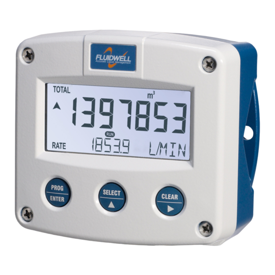
Page 6 OPERATIONAL • This device may only be operated by persons who are authorized and trained by the operator of the facility. All instructions in this manual are to be observed. • Take careful notice of the "Safety rules, instructions and precautionary measures" in the front of this manual. - Page 7 Page 7 ▪ Display line temperature When the SELECT/ key is pressed three times, the actual temperature is shown. Note that the actual flow rate shows on the bottom line intermittently. ▪ Display line pressure When the SELECT/ key is pressed two times, the actual pressure is shown. Note that the actual flow rate shows on the bottom line intermittently.
-
Page 8: Configuration
Page 8 CONFIGURATION This and the following chapters are exclusively meant for electricians and non-operators. In these, an extensive description of all software settings and hardware connections are provided. • Mounting, electrical installation, start-up and maintenance of this device may only be carried out by trained persons authorized by the operator of the facility. - Page 9 Page 9 The SELECT/▲ key and the CLEAR/► key are used for navigation. The explanation assumes that you are in the submenu TOTAL. When you are: • in the first setting and you navigate to the previous setting, the F126-P goes back to the related main menu.
-
Page 10: Setup Menu - Settings
Page 10 3.1.2. SETUP MENU - SETTINGS TOTAL unit ; kg; lb; GAL; USGAL; bbl; no unit decimals 0000000; 111111.1; 22222.22; 3333.333 K-Factor: 0.000010 - 9999999 decimals K-Factor 0 - 6 FLOW RATE unit mL; L; ; mg; g; kg; ton; gal; bbl; lb; cf; rev; - - - - (no unit); scf;... -
Page 11: Explanation Of Setup Menu 1 - Total
Page 11 3.1.3. EXPLANATION OF SETUP MENU 1 - TOTAL This setting is used to select the engineering unit for the indication of the total, UNIT the accumulated total and the pulse output. When you change the engineering unit, you must recalculate and reprogram the K-factor for the (accumulated) total. -
Page 12: Explanation Of Setup Menu 3 - Display
Page 12 FILTER This setting is used to stabilize the flow rate reading. With the help of this digital filter a more stable but less actual reading can be obtained. The filter principal is based on three input values: the filter level (01-99), the last calculated flow rate and the last average value. -
Page 13: Explanation Of Setup Menu 5 - Flowmeter
Page 13 3.1.7. EXPLANATION OF SETUP MENU 5 - FLOWMETER SIGNAL With this setting the type of flowmeter output is selected. The settings with LP (low-pass) filter are used to apply a build-in noise reduction. Selections "active pulse" offer a detection level of 50% of the supply voltage. -
Page 14: Explanation Of Setup Menu 7 - Pressure
Page 14 3.1.8. EXPLANATION OF SETUP MENU 7 - PRESSURE MEASURING UNIT This setting is used to program the temperature unit which is shown to the operator. This setting does not influence the actual calculations. SPAN With this setting, the measurement range of the (0)4-20mA pressure sensor is determined according the selected measurement unit. -
Page 15: Explanation Of Setup Menu 8 - Formula
Page 15 3.1.9. EXPLANATION OF SETUP MENU 8 - FORMULA EQUATIONS TYPE This setting shows the formula. The type EG stands for Equations Gas - flow computer for corrected gas volume. The formula used: Q = Q * (P/P ) * (T /T) * (C normal normal... -
Page 16: Explanation Of Setup Menu A - Pulse
Page 16 TUNE-MIN The (0)4mA or 0V value can be tuned precisely with this setting. The initial minimum analog output value is (0)4mA or 0V. However, this value might differ slightly due to ambient influences such as temperature for example. Before tuning the signal, make sure that the analog signal is idle (not used) for any application! After pressing PROG, the current will be about 4mA (0mA or 0V). -
Page 17: Explanation Of Setup Menu B - Communication (Option)
This product is designed for the connection to a communication network. Products with a communication option do not include cyber security functions. Fluidwell cannot take any responsibility for the cyber security, omissions or errors in the communication safety. To maintain a... -
Page 18: Installation
Page 18 INSTALLATION 4.1. GENERAL DIRECTIONS • Mounting, electrical installation, start-up and maintenance of this device may only be carried out by trained persons authorized by the operator of the facility. Persons must read and understand this manual before carrying out its instructions. •... -
Page 19: Dimensions- Enclosure
Page 19 4.3. DIMENSIONS- ENCLOSURE Aluminum and stainless enclosures (where “H” turns to “HS” for stainless, e.g. HA → HSA): 75 mm (2.95") 112 mm (4.40") 130 mm (5.12") 12mm 12mm 30mm 30mm 24mm 24mm M20 x 1,5 6 x M12 36mm 36mm 25mm... - Page 20 Page 20 75 mm (2.95") 130 mm (5.12") 112 mm (4.40") HK back box: (flat bottom) 75 mm (2.95") 118 mm (4.65”) 25mm 25mm D=20mm D=20mm 12mm 12mm 30mm 30mm 24mm 24mm D=12mm D=16mm D=16mm D=20mm 36mm 36mm 0.12” 0.12” D=22mm (0.866") 3x D=22mm (0.866”) 29.1 mm (1.15”)
-
Page 21: Installing The Hardware
The wire screens shall be terminated at one side to prevent wire loops. Inside of the Fluidwell unit, the different common ground terminals are connected to each other. It is advised, as illustrated, to terminate the wire screens in the vicinity of the sensor and to insulated the wire screen with a shrink tube at the Fluidwell unit side. -
Page 22: Protective Earth (Pe) Connections
Page 22 4.4.2. PROTECTIVE EARTH (PE) CONNECTIONS Inside the unit, different types of bonding and earthing are used. The common ground is mostly used for termination of the wire shields; the Protective Earth (PE) is used for electrical safety. For externally powered installations, route the Protective Earth (PE) grounding conductor into the enclosure together with the incoming power conductors. -
Page 23: Aluminum Enclosure - Field Mounted
Do not use the terminal 00 to connect the protective earth wire, the 00 and the common ground terminals are internally connected. Be careful, to prevent damage to equipment when you connect different power supplies (sensor, PLC, etc.). Inside the Fluidwell display, the common grounds are internally connected to each other. -
Page 24: Plastic (Grp) Enclosure
Page 24 4.4.5. PLASTIC (GRP) ENCLOSURE The PE connection The F126-P in a GRP enclosure meets the requirements of class 2 (double insulated). Therefore the incoming PE wire is terminated with an insulating end cap. Type PM (110-230V AC) Type OR (8-24V AC) Type OR (8-30V DC) FW_F126PEGTP_v1901_04_EN.docx... -
Page 25: Terminal Connectors
Page 25 4.4.6. TERMINAL CONNECTORS Refer to Appendix A: Technical Specification For Intrinsically safe applications: read chapter 5. Fig. 8: Overview of terminal connectors - Standard configuration and options 4.4.7. VOLTAGE SELECTION SENSOR SUPPLY For type PB/PC; PX; AP: There is no real sensor supply out available. Only a limited power supply is available. - Page 26 Page 26 Set the sensor supply 1. Make the F126-P safe. If applicable, mind the battery power. 2. Open the F126-P and carefully remove the cable-connectors and the protective cover. 3. Find and set the switches and select the V as required.
- Page 27 Page 27 Type OA: An active 24V DC pulse signal output is available with this option. Max. driving capacity 50mA@24V per output. . (Requires power supply type PD/PF/PM). Fig. 10: Terminal connections - Active output (typical) Type OR: A mechanical relay output is available with this option. Max. switch power 240V 0,5A per output. (Requires power supply type PF/PM).
- Page 28 Page 28 Type AA: An active 4-20mA signal proportional to the flow rate is available with this option. When the output is disabled, a 3.5mA signal will be generated on these terminals. Max. driving capacity 1000 Ohm @ 24VDC. (Requires power supply type PD/PF/PM). Fig.
- Page 29 Page 29 Type AU: A 0-10VDC signal proportional to the flow rate is available with this option. Max. load 10mA @ 10VDC. (Requires power supply type PD/PF/PM). Fig. 17: Terminal connections - Active 0-10V analog output (typical) Terminal 09-11; Flowmeter input: Three basic types of flowmeter signals can be connected to the unit: pulse, active pulse or sine- wave (coil).
- Page 30 Page 30 Pulse-signal PNP / PNP-LP: The F126-P is suitable for use with flowmeters which have a PNP output signal. 3V is offered on terminal 11 which has to be switched by the sensor to terminal 10 (SIGNAL). For a reliable pulse detection, the pulse amplitude has to go above 1.2V.
- Page 31 Page 31 NAMUR-signal: The F126-P is suitable for flowmeters with an Namur signal. The standard F126-P is not able to power the Namur sensor, as an external power supply for the sensor is required. However, a 8.2V sensor supply voltage (terminal 11) can be provided with power supply type PD, PF, PM. Fig.
-
Page 32: Intrinsically Safe Applications
Please note • Certificates, safety values, control drawing and declaration of conformity can be found in the document named: “Fluidwell F1..-..-XI - Documentation for Intrinsic safety”. • When installing this device in hazardous areas, the wiring and installation must comply with the appropriate installation standards for your industry. - Page 33 Page 33 Serial number and year of production This information can be looked-up in the setup menu: Others. Fig. 25: Example serial number (typical) Label information pulse input type – F1xx-..-..-XI (inside and outside the enclosure) Fig. 26: Label information - Intrinsically safe application (typical) FW_F126PEGTP_v1901_04_EN.docx...
-
Page 34: Terminal Connectors Intrinsically Safe Applications
3 and 4 and/or terminals 5 and 6; the maximum values for any of those circuits are those as defined for group IIB/IIIC. Terminal connectors F126-P-EG-TP-XI: For intrinsically safe applications, consult the safety values in the certificate. - Page 35 Page 35 Explanation Intrinsically safe options: Type AF – Intrinsically safe floating 4-20mA analog output: A floating 4-20mA signal proportional to the flow rate is available with this option. When the output is disabled, a 3.5mA signal will be generated. Max. driving capacity 1000 Ohm @ 30V DC. Fig.
-
Page 36: Configuration Examples
Page 36 CONFIGURATION EXAMPLES Fig. 30: F126-P-(AP)-(CT)-EG-IA-(OT)-PC-TP-XI - Battery powered - IIB/IIC - IIIC Fig. 31: F126-P-AP-CT-EG-IA-OT-(PX)-TP- XI - Output loop powered - IIB/IIC - IIIC FW_F126PEGTP_v1901_04_EN.docx... -
Page 37: Battery Replacement Instructions
Page 37 BATTERY REPLACEMENT INSTRUCTIONS 5.4.1. SAFETY INSTRUCTIONS • Handle the battery with care. A mistreated battery can become unsafe. Unsafe batteries can cause (serious) injury to persons. • Only use batteries which are certified for use in hazardous areas. The use of standard batteries in hazardous area's is not safe and prohibited. -
Page 38: Maintenance
Repairs should only be carried out by the manufacturer or his authorized agent. 6.3. REPAIR POLICY If you have any problem with your Fluidwell product and you wish to repair it, please follow the procedure below: a. Obtain a Return Material Authorization (RMA) from your supplier or distributor Together with the RMA, you need to complete a repair form to submit detailed information about the problem. -
Page 39: Appendix A: Technical Specifications
Page 39 APPENDIX A: TECHNICAL SPECIFICATIONS General Display Type High intensity reflective numeric and alphanumeric LCD, UV-resistant. Digits Seven 17mm (0.67”) and eleven 8mm (0.31”). Various symbols and measuring units. Refresh rate User definable: 8 times/sec – 30 secs. Type ZB LCD with LED backlight. - Page 40 Page 40 Terminal connections Type: Removable plug-in terminal strip. Wire max. 1.5m m and 2.5m m Data protection Type EEPROM backup of all setting. Backup of running totals every minute. Data retention at least 10 years. Password Configuration settings can be password protected. Hazardous area Intrinsically safe ATEX approval :...
- Page 41 Page 41 Outputs Analog output Function transmitting compensated flow rate. Accuracy 10 bit. Error < 0.05% - update 10 times a second. Software function to calibrate the 4.00mA and 20.00mA levels precisely within set-up. Load max. 1 kOhm Type AA Active 4-20mA output (requires type OA + PD, PF or PM).
-
Page 42: Appendix B: Problem Solving
Page 42 APPENDIX B: PROBLEM SOLVING In this appendix, several problems are included that can occur when the F126-P-EG is going to be installed or while it is in operation. Flowmeter does not generate pulses: Check: ▪ Signal selection; ▪ Pulse amplitude;... -
Page 43: Appendix C: Communication Variables
Page 43 APPENDIX C: COMMUNICATION VARIABLES General The product is fitted with the Modbus communication protocol and can be equipped with various physical interfaces like RS485 and RS232 (please see device datasheet for available options). The tables below show the various variables that can be accessed through the communication. Currently, the function codes supported are: •... - Page 44 Page 44 For example when two decimals are selected for total and total has a value of 123456,78 the display will show 23456,78 while communication will read a “total” of 12345678 and a “total decimals” of 2. * Clearing total: It is possible to clear the total counter by means of writing a value of 0 to all the 3 registers of total/flow rate in a single write action.
- Page 45 Page 45 REGISTER VARIABLE R/W TYPE VALUE / REMARKS ADDRESS TEMPERATURE REGISTERS [d] 209 40210 display r/w uint16 0: °C 1: °F 2: K [h] 0x0D1 [d] 208 40209 number of wires r/w uint16 0: 2 1: 3 [h] 0x0D0 [d] 199 40200 filter...
- Page 46 Page 46 REGISTER VARIABLE R/W TYPE VALUE / REMARKS ADDRESS PULSE OUTPUT REGISTERS [d] 128 40129 pulse width r/w uint16 0…9999, (0=disabled) [h] 0x080 Representation: 0.000 – 9.999 sec [d] 133 40134 decimals r/w uint16 0…3 [h] 0x085 [d] 130 40131 amount r/w uint32...
-
Page 47: Appendix D: Declaration Of Conformity
Page 47 APPENDIX D: DECLARATION OF CONFORMITY FW_F126PEGTP_v1901_04_EN.docx... -
Page 48: Index Of This Manual
Page 48 INDEX OF THIS MANUAL accumulated Total IP classification actual settings Low-battery alarm analog maintenance floating output. model flowrate min. NAMUR-signal intrinsically safe output. operational 6, 8, 9, 18, 38 tune / calibrate operator level Analog output pass code backlight power supply 26, 27... -
Page 49: List Of Figures In This Manual
Page 49 LIST OF FIGURES IN THIS MANUAL Fig. 1: Typical application ........................5 Fig. 2: Control Panel ..........................6 Fig. 3: Process information (typical) ......................6 Fig. 4: Low-battery alarm (typical) ......................7 Fig. 5: Aluminum and stainless enclosures - Dimensions ..............19 Fig. - Page 50 Page 50 NOTES ……………………………………………………………………………………………………………………. ……………………………………………………………………………………………………………………. ……………………………………………………………………………………………………………………. ……………………………………………………………………………………………………………………. ……………………………………………………………………………………………………………………. ……………………………………………………………………………………………………………………. ……………………………………………………………………………………………………………………. ……………………………………………………………………………………………………………………. ……………………………………………………………………………………………………………………. ……………………………………………………………………………………………………………………. ……………………………………………………………………………………………………………………. ……………………………………………………………………………………………………………………. ……………………………………………………………………………………………………………………. ……………………………………………………………………………………………………………………. ……………………………………………………………………………………………………………………. ……………………………………………………………………………………………………………………. ……………………………………………………………………………………………………………………. ……………………………………………………………………………………………………………………. ……………………………………………………………………………………………………………………. ……………………………………………………………………………………………………………………. ……………………………………………………………………………………………………………………. ……………………………………………………………………………………………………………………. ……………………………………………………………………………………………………………………. ……………………………………………………………………………………………………………………. ……………………………………………………………………………………………………………………. ……………………………………………………………………………………………………………………. ……………………………………………………………………………………………………………………. ……………………………………………………………………………………………………………………. ……………………………………………………………………………………………………………………. ……………………………………………………………………………………………………………………. ……………………………………………………………………………………………………………………. ……………………………………………………………………………………………………………………. FW_F126PEGTP_v1901_04_EN.docx...
- Page 51 Page 51 LIST OF CONFIGURATION SETTINGS SETTING DEFAULT DATE : DATE : 1 - TOTAL Enter your settings here 11 unit 12 decimals 0000000 13 K-factor 0000001 14 decimals K-factor 2 - FLOW RATE 21 unit 22 time /min 23 decimals 0000000 24 K-factor 0000001...
- Page 52 Page 52 Fluidwell BV PO box 6 Voltaweg 23 Website: www.fluidwell.com FW_F126PEGTP_v1901_04_EN.docx 5460 AA Veghel 5466 AZ Veghel Find your nearest representative: www.fluidwell.com/representatives The Netherlands The Netherlands © 2021 Fluidwell BV - FW_F126PEGTP_v1901_04_EN.docx...
Need help?
Do you have a question about the F126-P-EG-TP and is the answer not in the manual?
Questions and answers