Table of Contents
Advertisement
Quick Links
Advertisement
Table of Contents

Related Manuals for Gomax MX-2003B


Summary of Contents for Gomax MX-2003B
- Page 1 MX-2003B Dual-View Video Processor User Manual Made in Taiwan...
-
Page 2: Safety And Notice
The MX-2003B Dual-View Video Processor has been tested for conformity to safety regulations and requirements, and has been certified for international use. However, like all electronic equipments, the MX-2003B should be used with care. Please read and follow the safety instructions to protect yourself from possible injury and to minimize the risk of damage to the unit. - Page 3 Introduction General The MX-2003B Dual-View Video Processor is an advanced video processor for multimedia presentations. It is an ideal solution for applications where two video signals must be displayed on a single display. It supports up to four video inputs, of which two can be outputted simultaneously in Picture-In-Picture (PIP) or Picture-Aside-Picture (PAP) modes.
- Page 4 Features Three graphic (DVI / VGA) and four video (HDMI /Component / S-Video / Composite) Inputs, from 640x480 to 1920x1200, interlaced or progressive. Dual outputs (DVI / VGA), 640x480 to 1920x1200. HDCP 1.1 Support PIP, PAB, Full screen modes and adjustable size& position through software. ...
-
Page 5: Specifications
Operation temperature 0~40C [32~104F] Storage temperature -20~60C [-4~140F] Relative humidity 20~90% RH [no condensation] 1x MX-2003B or MX-1003B 1x 5V power adapter 1x DVI to DVI&VGA breakout cable 1x IR remote controller Package Contents 1x VGA to component breakout cable... -
Page 6: Package Contents
Package Contents 1. MX-2003B 2. DVI to DVI & VGA breakout cable (DDVY01) 3.VGA to component breakout cable 4. DVI to VGA adapter (DVA01) (VYPBA01) 5. 5V DC power adapter 6.IR remote controller 7. Installation software CD 8. User Manual Please visit www.gomax-electronics.com/download.htm... -
Page 7: Inputs And Outputs
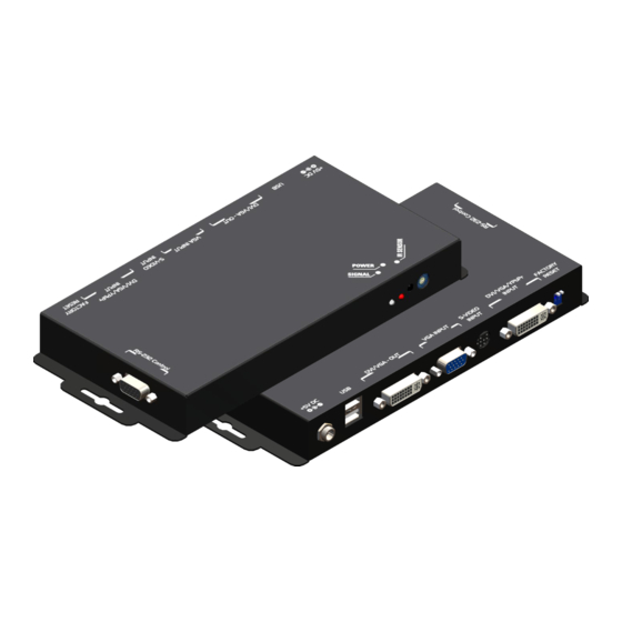
You can pick up two of the four inputs, one is for main channel and the other is for sub channel, and then display two of them simultaneously on the same screen. Figure 2 shows the rear panel connectors of a MX-2003B and Table 1 illustrates how you can connect video devices and display to the MX-2003B. -
Page 8: Hardware Installation
Installation Procedures Unpacking Remove the MX-2003B from the shipping container and examine it for any signs of shipping damage or missing items (check with package contents above). All shipping items should be saved if the product is to be moved or returned for service. Shipping unit back to dealers for service not in the original box may result in voiding warranty or additional cost. - Page 9 2. Connect a monitor, a projector or other displays that comes with DVI and/or VGA inputs by using 1 male-to-male DVI (VGA) cable to MX-2003B DVI output (you can connect 2 displays equipped with DVI and VGA respectively by a DVI to DVI/VGA breakout cable (DDVY01)) .
-
Page 10: Ir Remote Control
IR Remote Control The MX-2003B is now shipped with a compact remote control that allows for direct access to most commands used to control the video processor. Table 2: IR Functionalities Mute Mute the audio output Power Power on/off the device... - Page 11 On Screen Display Menu Image Settings Scheme: Normal, Vivid, Cinema, Game, Sport Five slider controls for video quality: Brightness, Contrast, Saturation, Hue, Sharpness Advanced: Noise Reduction, Flash tone, Dynamic Contrast, Color Noise Reduction: MPEG NR (MPEG Noise Reduction) Temporal NR (Temporal Noise Reduction) Flash tone: Enhance Flash Dynamic Contrast: 5 Level Control Color: User Defined Color Temperature...
- Page 12 Display Settings Auto Aspect Ratio Aspect Ratio: 16:9, Letter Box, Pillow Box Expand Resolution: Define the output’s resolution 800x600@60, 1024x768@60, 1280x1024@60, 1280x720@60, 1366x768@60, 1440x900@60, 1400x1050@60, 1920x1080@60, 1920x1200@60, 1600x1200@60 PIP: PIP Mode: off, Large PIP, Small PIP, Side by Side (PBP) PIP Position: Bottom-Right, Bottom-Left, Top-Left, Top-Right Multi-PIP Configuration: POP7, 3x3 GRID, POP3, POP12 Multi-PIP On*: YES, NO...
-
Page 13: Operation Software
Operation Software System Requirement and Precautions 1. The MX-1003B provides a software control program which runs under Microsoft Windows 98, 2000, XP through the interface of RS-232 serial control. 2. Before you click on the icon of the software, make sure you have secured the connection between your computer COM port and the MX-1003B and switched on the MX-1003B with green LED light. - Page 14 3. If the serial connection is well established, you can see similar work window as below. 4. While you move the mouse’s cursor near the borders, in either red or blue, the icon of the cursor will change as the figure below. ~12~...
-
Page 15: Instruction Of Software Operation
Instruction of Software Operation File a. Connect: This will synchronize the status of the MX-1003B with that of the software, especially after IR commands sent. b. Save Setting: This will save current user preferred settings such as the positions and sizes of the videos, the width or color of border etc. into your favorite setting files. - Page 16 1. Assign an ID for the connected MX-1003B: type a number in the “ID Number” of the device ID setting area and then click “Write”. 2. Read the ID of the connected MX-1003B: click “Read” and the ID will show up. 3.
- Page 17 Main a. Input Source: Select a video/graphic input of the main channel. b. Visible: Display the main channel or not. c. Border: Display the main channel’s border. d. Label: Display the main channel’s label. Users can define the content of the label. e.
- Page 18 Control- Setting Dialog Border Select main or sub channel for further setting. PAP mode only 1. Border Color: Setup border’s color by clicking on “Color setting”. 2. Border Width: Input border’s width. 3. Border Type: The placement of border has two types: Option Inside means the added border is fully inside the video.
- Page 19 6. Duty Cycle: The duty cycle of blinking of OSD borders and labels. 7. Frequency: How fast the blink. Image 1. Choose the scaling type for the main channel at full screen display. 2. While Blend is selected, users can use the slider to control the degree of blending. There is a short period of slight blinking while the MX-1003B processes the blending of the two input videos.
- Page 20 Color 1. Select the main or sub channels. 2. Reset: Restore all the setting on this page back to their default values. Zoom A. Select the main or sub channel. B. Default: Restore the selected channel without zoom effect. ~18~...
- Page 21 A. This scroll bar controls the ratio of Zoom. B. The workplace for controlling the displayed area after zooming the selected video. Pattern 1. While “Pattern Model” is chosen, the output will display the selected pattern. While unselecting this item, the output display works normally.
- Page 22 HS / VS Delay 1. Select the main or sub channel. 2. Adjust Main /Sub Channel size and position 3. The fine movement of the selected channel. EDID Code 1. Save: Save the read back EDID Content in PC. 2. Setting: Automatically setup the output resolution according to the content of EDID.
-
Page 23: Troubleshooting
Troubleshooting Problem Recommendations Check if you are using 5V DC adapter and it is firmly plugged into the No power MX-1003B If you are recovering from power outage, accidentally unplug the adapter or other power surge conditions, leave the device off for a while and then power it on again. -
Page 24: Limited Warranty
Limited Warranty The SELLER warrants the MX-2003B Dual-View Video Processor to be free from defects in the material and workmanship for 1 year from the date of purchase from the SELLER or an authorized dealer. Should this product fail to be in good working order within 1 year warranty period, The SELLER, at its option, repair or replace the unit, provided that the unit has not been subjected to accident, disaster, abuse or any unauthorized modifications including static discharge and power surges. -
Page 25: Appendix - Supported Resolution
Appendix – Supported Resolution [DVI-IN1] Socket Supported Mode Resolution Supported Mode Resolution NTSC/480I/525I 720x240 @60Hz 832x624 @75Hz PAL/576I/625I 720x288 @50Hz VESA 1024x768 @60Hz 480P/525P 720x483 @60Hz 1024x768 @60Hz 480P (16:9) 960x483 @60Hz VESA 1024x768 @70Hz 576P/625P 720x756 @50Hz 1024x768 @72Hz (HDTV) 720p 1280x720 @50Hz VESA... - Page 26 [DVI-IN2] Socket Supported Mode Resolution VESA 640x480 @60Hz VESA 800x600 @60Hz VESA 1024x768 @60Hz VESA 1280x1024 @60Hz VESA 1600x1200 @60Hz VESA 1920x1200 @60Hz [DVI-I OUT] Socket Supported Mode Resolution (HDTV) 720p 1280x720 @50Hz (HDTV) 720p 1280x720 @60Hz (HDTV) 1080p 1920x1080 @60Hz VESA 640x480 @60Hz VESA...
Need help?
Do you have a question about the MX-2003B and is the answer not in the manual?
Questions and answers