Table of Contents
Advertisement
Quick Links
Application
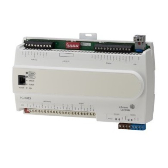
The PCA3613 controller runs pre-engineered and user-programmed applications and provide
the inputs and outputs required to monitor and control a wide variety of HVAC and other facility
equipment.
PCA36 controllers operate on an RS-485 BACnet
and third-party BACnet systems.
PCA36 controllers include an integral real-time clock, which enables the controllers to monitor and
control schedules, calendars, and trends, and operate for extended periods of time as stand-alone
controllers when offline from the system network.
Communications protocols
By default, the controllers communicate using the standard BACnet MS/TP protocol based on the
ANSI/ASHRAE 135-2012. The BACnet protocol is a standard for ANSI, ASHRAE, and the International
Standards Organization (ISO) for building controls.
North American Emissions Compliance
United States
This equipment has been tested and found to comply with the limits for a Class A digital device
pursuant to Part 15 of the FCC Rules. These limits are designed to provide reasonable protection
against harmful interference when this equipment is operated in a commercial environment.
This equipment generates, uses, and can radiate radio frequency energy and, if not installed
and used in accordance with the instruction manual, may cause harmful interference to
radio communications. Operation of this equipment in a residential area may cause harmful
interference, in which case the users will be required to correct the interference at their own
expense.
Canada
This Class (A) digital apparatus meets all the requirements of the Canadian Interference-Causing
Equipment Regulations.
Cet appareil numérique de la Classe (A) respecte toutes les exigences du Règlement sur le
matériel brouilleur du Canada.
Installation
Observe the following guidelines when installing a PCA3613:
• To minimize vibration and shock damage, transport the controller in the original container.
• Verify that all parts shipped with the controller.
• Do not drop the controller or subject it to physical shock.
Part No. 24-10143-1175 Rev C
2019-03-22
PCA3613 Advanced Application
Programmable Controller Installation
MS/TP Bus and integrate into Johnson Controls
®
Instructions
*24101431175C*
(barcode for factory use only)
CH-PCA3613
®
Advertisement
Table of Contents

Subscribe to Our Youtube Channel
Related Manuals for Johnson Controls PCA3613


Summary of Contents for Johnson Controls PCA3613
- Page 1 Programmable Controller Installation Instructions Application The PCA3613 controller runs pre-engineered and user-programmed applications and provide the inputs and outputs required to monitor and control a wide variety of HVAC and other facility equipment. PCA36 controllers operate on an RS-485 BACnet MS/TP Bus and integrate into Johnson Controls ®...
- Page 2 • Do not mount the controller in areas where electromagnetic emissions from other devices or wiring can interfere with controller communication. Observe these additional guidelines when mounting a PCA3613 in a panel or enclosure: • Mount the controller so that the enclosure walls do not obstruct cover removal or ventilation through the controller.
-
Page 3: Din Rail Mount Applications
DIN rail. Wall mount applications To mount a PCA3613 directly on a wall or other flat vertical surface, complete the following steps: Pull the two bottom mounting clips outward and ensure they are locked in the extended position as shown in Figure 2. - Page 4 Figure 2: Back of Controller showing extended mounting clips, DIN rail channel, and mounting dimensions, mm (in.) PCA3613 Advanced Application Programmable Controller Installation Instructions...
- Page 5 Universal Inputs (UI) Terminal Block: Can be defined as Voltage Analog Input (0–10 VDC), Current Analog Input (4–20 mA), Resistive Analog Inputs (0–600k ohms), or Dry Contact Binary Input (see Input and Output wiring guidelines) PCA3613 Advanced Application Programmable Controller Installation Instructions...
- Page 6 Important: Use copper conductors only. Make all wiring in accordance with local, national, and regional regulations. Important: Electrostatic discharge can damage controller components. Use proper electrostatic discharge precautions during installation, setup, and servicing to avoid damaging the controller. PCA3613 Advanced Application Programmable Controller Installation Instructions...
-
Page 7: Terminal Blocks And Bus Ports
Bus Technical Bulletin (LIT-12011670). Terminal blocks and bus ports PCA3613 physical features for terminal block and bus port locations on the PCA3613 controller. Observe the following guidelines when wiring a PCA3613 controller. Input and Output terminal blocks The fixed input terminal blocks are located on the bottom of the controller, and the output terminal blocks are located on the top of the controller. -
Page 8: Fc Bus Port
• The MAP Gateway serves as a replacement for the BTCVT, which is no longer available for purchase, but continues to be supported. Figure 6: Pin number assignments for sensor, SA bus, and FC bus ports on Controllers PCA3613 Advanced Application Programmable Controller Installation Instructions... -
Page 9: Sensor Port
Powering network devices with uniform 24 VAC supply power phasing reduces noise, interference, and ground loop problems. The controller does not require an earth ground connection. PCA3613 Advanced Application Programmable Controller Installation Instructions... -
Page 10: Termination Diagrams
Termination diagrams A set of Johnson Controls termination diagrams provides details for wiring inputs and outputs to the controllers. See the figures in this section for the applicable termination diagrams. Table 2: Termination details Type of field Type of Termination diagrams... - Page 11 Input/ Output Current Input - External Source (Isolated) Current Input - Internal Source (2- wire) Current Input - Internal Source (3 wire) Current Input - External Source (in Loop) Feedback from EPP-1000 PCA3613 Advanced Application Programmable Controller Installation Instructions...
- Page 12 Input/ Output Dry Contact UI or BI (Binary Input) 0–10 VDC Output to Actuator (External Source) 0–10 VDC Output to Actuator (Internal Source) Current Output 24 VAC Triac Output (Switch Low, External Source) PCA3613 Advanced Application Programmable Controller Installation Instructions...
- Page 13 Table 2: Termination details Type of field Type of Termination diagrams device Input/ Output Analog Output (Current) 4–20 mA Output to Actuator 4–20 mA Output to Actuator Incremental Control to Actuator (Switch Low, Externally Sourced) PCA3613 Advanced Application Programmable Controller Installation Instructions...
- Page 14 SA Bus Stat with Phone Jack (Fixed Address = 199) Note: The bottom jack (J2) on the TE-700 and TE-6x00 Series Sensors is not usable as a zone bus or an SAB connection. PCA3613 Advanced Application Programmable Controller Installation Instructions...
-
Page 15: Terminal Wiring Guidelines, Functions, Ratings, And Requirements
• Shielded cable is not required for input or output cables. • Shielded cable is recommended for input and output cables that are exposed to high electromagnetic or radio frequency noise. PCA3613 Advanced Application Programmable Controller Installation Instructions... -
Page 16: I/O Terminal Blocks, Ratings, And Requirements
® Silicon Temperature Sensor) Negative Temperature Coefficient (NTC) Sensor Binary Input - Dry Contact Maintained See Guideline A in Mode Table 4. 1 second minimum pulse width Internal 12 V. 15k ohms pull-up PCA3613 Advanced Application Programmable Controller Installation Instructions... - Page 17 Note: The Analog Output (AO) operates in the Voltage Mode when connected to devices with impedances greater than 1,000 ohms. Devices that drop below 1,000 ohm may not operate as intended for Voltage Mode applications. PCA3613 Advanced Application Programmable Controller Installation Instructions...
-
Page 18: Cable And Wire Length Guidelines
(<30 V) input and outputs. Note: The required wire sizes and lengths for high-voltage (>30 V) Relay Outputs are determined by the load connected to the relay, and local, national, or regional electrical codes. PCA3613 Advanced Application Programmable Controller Installation Instructions... -
Page 19: Maximum Cable Length Versus Load Current
Use Figure 8 to estimate the maximum cable length relative to the wire size and the load current (in mA) when wiring inputs and outputs. Note: Figure 8 applies to low-voltage (<30 V) inputs and outputs only. PCA3613 Advanced Application Programmable Controller Installation Instructions... -
Page 20: Communications Bus And Supply Power Wiring Guidelines
38.4k baud. For more information, refer to the following documents depending on your system (FX or BCPro): MS/TP Communications Bus for the BCPro System Technical Bulletin (LIT-12011908) or FX-PC Series Controllers MS/TP Communications Bus Technical Bulletin (LIT-12011670). PCA3613 Advanced Application Programmable Controller Installation Instructions... - Page 21 24 VAC Power Supply - Hot 0.8 mm to 1.0 mm Supply 20–30 VAC (Nominal 24 VAC) (18 AWG) 2-wire 24 VAC Power Supply Common (Isolated from all other Common terminals on controller) 14 VA PCA3613 Advanced Application Programmable Controller Installation Instructions...
-
Page 22: Setup And Adjustments
Setting the device address The PCA3613 is a device on an MS/TP (SA or FC) bus. Before you operate PCA controllers on a bus, you must set a valid and unique device address for each controller on the bus. You set a PCA3613 controller's device address by setting the positions of the switches on the DIP switch block at the top of the controller . -
Page 23: Removing The Controller Cover
Pivot the top of the cover further to release it from the lower two latches. Replace the cover by placing it squarely over the base, and then gently and evenly push the cover on to the latches until they snap into the latched position. PCA3613 Advanced Application Programmable Controller Installation Instructions... -
Page 24: Setting The End-Of-Line (Eol) Switch
See Figure 10 for the EOL switch location. The default EOL switch position is Off. Figure 11: End-of-Line switch positions To set the EOL switch on a PCA3613 controller, complete the following steps: Determine the physical location of the controller on the FC bus. -
Page 25: Setting The Input Jumpers
The UI current loop fail-safe jumper pins are located on the circuit board under the controller cover near the UI terminals (Figure 10). Note: Current Loop Jumpers are not included with the PCA3613-0. Figure 12: Current loop jumper positions Set the current loop jumper to the Enabled position (Figure 12) to connect an internal 100 ohms resistor across the UI terminals, which maintains the 4–20 mA current loop circuit even when power... -
Page 26: Troubleshooting The Controllers
Table 7: PCA3613 UI Inputs and jumper labels Universal Input label Jumper label on circuit board Commissioning the Controllers You commission BACnet MS/TP controllers with the Controller Configuration Tool (CCT) software, either via a Bluetooth Wireless Commissioning Converter, a ZFR wireless dongle, or in ®... -
Page 27: Repair Information
Off Steady = EOL switch in Off position terminating devices) Repair information If the PCA3613 controller fails to operate within its specifications, replace the controller. For a replacement controller, contact your Johnson Controls representative. Accessories Table 9: Accessories ordering information... -
Page 28: Technical Specifications
Technical specifications Table 10: PCA3613 Advanced Application Programmable Controller Product Code Numbers CH-PCA3613-0 Advanced Application Programmable Controller Note: This model is currently only available in Asia and the Middle East. Power Requirement 24 VAC (nominal, 20 VAC minimum/30 VAC maximum), 50/60 Hz,... - Page 29 Canada: UL Listed, File E107041, CCN PAZX7 CAN/CSA C22.2 No. 205, Signal Equipment Industry Canada Compliant, ICES-003 Europe: Johnson Controls declares that this product is in compliance with the essential requirements and other relevant provisions of the EMC Directive. Australia and New Zealand: RCM Mark, Australia/NZ Emissions Compliant BACnet International: BACnet Testing Laboratories™...
-
Page 30: Points Of Single Contact
NO. 32 CHANGJIJANG RD NEW DISTRICT 45143 ESSEN MILWAUKEE WI 53202 WUXI JIANGSU PROVINCE 214028 GERMANY CHINA © 2019 Johnson Controls. All rights reserved. All specifications and other information shown were current as of document revision and are subject to change without notice. www.johnsoncontrols.com...
Need help?
Do you have a question about the PCA3613 and is the answer not in the manual?
Questions and answers