Table of Contents
Advertisement
Quick Links
Applications
The PCV1617 and PCV1632 are programmable digital controllers designed for VAV box applications
that communicate through the BACnet
pressure sensor, a damper actuator, and a 32-bit microprocessor. The controllers' small package
size facilitates quick field installation and efficient use of space without compromising high-tech
control performance. The PCV controllers connect easily to either the networked or to the non-
communicating sensor for zone air temperature sensing.
Communications Protocol
The PC family controllers and network sensors communicate using the standard BACnet protocol,
based on the ANSI/ASHRAE 135-2008. The BACnet protocol is a standard for ANSI, ASHRAE, and the
International Standards Organization (ISO) for building controls.
PCV field controllers are BTL-listed as BACnet Application Specific Controllers (B-ASCs).
North American Emissions Compliance
United States
This equipment has been tested and found to comply with the limits for a Class A digital device
pursuant to Part 15 of the FCC Rules. These limits are designed to provide reasonable protection
against harmful interference when this equipment is operated in a commercial environment.
This equipment generates, uses, and can radiate radio frequency energy and, if not installed
and used in accordance with the instruction manual, may cause harmful interference to
radio communications. Operation of this equipment in a residential area may cause harmful
interference, in which case the users will be required to correct the interference at their own
expense.
Canada
This Class (A) digital apparatus meets all the requirements of the Canadian Interference-Causing
Equipment Regulations.
Cet appareil numérique de la Classe (A) respecte toutes les exigences du Règlement sur le
matériel brouilleur du Canada.
Installation
Observe these guidelines when installing the PCV1617 and PCV1632 controllers:
• Transport the PCV controller in the original container to minimize vibration and shock damage to
the PCV controller.
• Do not drop the PCV controller or subject it to physical shock.
Part No. 24-10143-1299 Rev B
2019-03-22
PCV1617 and PCV1632 VAV Box Controllers
MS/TP protocol. The controllers feature an integral digital
®
Installation instructions
*2410143299B*
(barcode for factory use only)
CH-PCV1617, CH-PCV1632
Advertisement
Table of Contents
Troubleshooting

Subscribe to Our Youtube Channel
Related Manuals for Johnson Controls PCV1617


Summary of Contents for Johnson Controls PCV1617
- Page 1 PCV1617 and PCV1632 VAV Box Controllers Installation instructions Applications The PCV1617 and PCV1632 are programmable digital controllers designed for VAV box applications that communicate through the BACnet MS/TP protocol. The controllers feature an integral digital ® pressure sensor, a damper actuator, and a 32-bit microprocessor. The controllers' small package size facilitates quick field installation and efficient use of space without compromising high-tech control performance.
-
Page 2: Parts Included
• Do not mount the PCV in areas where electromagnetic emissions from other devices or wiring can interfere with controller communication. • When using the PCV1617 or PCV1632 to replace an existing controller, plug the unused open hole from the original controller mounting, if possible. - Page 3 PCV controller and the other ends of the tubing to the pressure transducer in the VAV box application. Note: The PCV uses a digital non-flow pressure sensor with bidirectional flow operation, which allows the high- and low-pressure DP tube connections to be made to either PCV1617 and PCV1632 VAV Box Controllers Installation instructions...
- Page 4 Faire pivoter le registre pour le placer en position d'ouverture complète avant de démarrer l'unité de traitement d'air. Le non-respect de cette directive risque d'endommager le caisson de l'unité à volume d'air variable (VAV) ou le réseau de conduites au démarrage de l'unité de traitement d'air. PCV1617 and PCV1632 VAV Box Controllers Installation instructions...
-
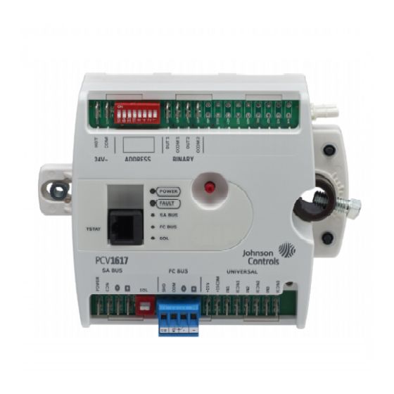
Page 5: Wiring Diagram
Wiring diagram Figure 2: PCV1617/PCV1632 Controller wiring terminations and physical features Table 1: PCV1617/PCV1632 features callout numbers and descriptions Callout Physical features: description and references 24 VAC, Class 2 Supply Power Spade Terminals (see Supply power terminal block) Device Address DIP Switch Block (see... - Page 6 PCV terminals and bus ports See Figure 2 for input and output terminal and bus port locations on the PCV1617 and PCV1632 controllers. Observe the following guidelines when wiring a PCV controller. PCV1617 and PCV1632 VAV Box Controllers Installation instructions...
-
Page 7: Input And Output Terminals
Wire the SA Bus terminal blocks on the PCV and other SA Bus devices, such as a communicating NS- family room sensor, in a daisy-chain configuration using 4-wire twisted, shielded cable as shown in the following diagram. . See Table 5 for more information. PCV1617 and PCV1632 VAV Box Controllers Installation instructions... -
Page 8: Modular Port
Supply power terminal block The 24 VAC supply power terminal block is a gray, removable, 2-terminal plug that fits into a board- mounted jack on the upper left of the PCV controller. PCV1617 and PCV1632 VAV Box Controllers Installation instructions... - Page 9 24 VAC power supply on -1 PCV models. A short circuit may result in a tripped circuit breaker or blown fuse. If using a transformer with a built-in fuse, the transformer may need to be replaced. PCV1617 and PCV1632 VAV Box Controllers Installation instructions...
-
Page 10: Input And Output Wiring Guidelines
Table 5 provides information about terminal block functions, ratings, and requirements. Table 5 also provides wire size, cable type, and cable length guidelines for wiring the PCV communication buses and supply power. PCV1617 and PCV1632 VAV Box Controllers Installation instructions... -
Page 11: Input And Output Wiring Guidelines Tables
Type L) or 2.252K Type Binary Input - Dry Contact See Guideline A in Maintained Mode Table 3. 1 second minimum pulse width Internal 12 V, 15k ohm pull up PCV1617 and PCV1632 VAV Box Controllers Installation instructions... - Page 12 40 mA minimum load current OCOMn Analog Output Signal Common: Same as (Configurable) All Configurable Outputs defined as OUTn. Analog Outputs share a common, which is isolated from all other commons except the Binary Input common. PCV1617 and PCV1632 VAV Box Controllers Installation instructions...
-
Page 13: Termination Diagrams
Use twisted wire cable. Termination diagrams A set of Johnson Controls termination diagrams provides details for wiring inputs and outputs to the controllers. See the figures in this section for the applicable termination diagrams. PCV1617 and PCV1632 VAV Box Controllers Installation instructions... - Page 14 Type of field Type of Input/Output device termination diagrams Temperature Sensor Voltage Input - External Source Voltage Input - Internal Source Voltage Input (Self-Powered) Dry Contact 0–10 VDC Output to Actuator (External Source) PCV1617 and PCV1632 VAV Box Controllers Installation instructions...
- Page 15 24 VAC Triac Output (Switch Low, External Source) Incremental Control to Actuator (Switch Low, External Source) 24 VAC Binary Output (Switch Low, Internal Source) Incremental Control to Actuator (Switch Low, Internal Source) PCV1617 and PCV1632 VAV Box Controllers Installation instructions...
- Page 16 Note: The bottom jack (J2) on the TE-700 and TE-6x00 Series Sensors is not usable as a zone bus or a SAB connection. Network Stat SA Bus with Terminals Addressable Network Stat SA Bus with Terminals (Fixed Address = 199) PCV1617 and PCV1632 VAV Box Controllers Installation instructions...
-
Page 17: Communication Bus And Supply Power Table
Note: The + and - SA PWR 15 VDC Supply Power for wires are one twisted Devices on the SA Bus pair, and the COM and SA PWR wires are the second twisted pair. PCV1617 and PCV1632 VAV Box Controllers Installation instructions... -
Page 18: Setup And Adjustments
The DIP switch block (Figure 9) has eight switches numbered 128, 64, 32, 16, 8, 4, 2, and 1. Switches 64 through 1 are device address switches. Switch 128 must be set to OFF for all hard-wired SA and FC Bus applications. PCV1617 and PCV1632 VAV Box Controllers Installation instructions... - Page 19 4. Write each PC controller’s device address on the white label below the DIP switch block on the controller’s cover. Table 6 shows and describe the valid FC Bus and SA Bus device addresses for Johnson Controls MS/ TP communications bus applications.
-
Page 20: Setting The Eol Switch
BACnet MS/TP protocol. Repair information If the PCV1617 or PCV1632 controller fails to operate within its specifications, replace the unit. For a replacement unit, contact the nearest Johnson Controls representative. PCV1617 and PCV1632 VAV Box Controllers Installation instructions... -
Page 21: Troubleshooting
Troubleshooting Table 8 provides LED status indicator information for troubleshooting the PCV1617 and PCV1632 controllers. Table 7 provides some additional troubleshooting information for possible problems. Note: If you experience short circuits in the 24 VAC power supply that cause protective devices such as breakers or fuses to trip, make sure that the power connections on the PCV are not reversed. -
Page 22: General Troubleshooting
4. Reset the breaker/fuse or replace the transformer. Note: When replacing the transformer, it is recommended to replace with a model that utilizes a resettable circuit breaker. A circuit breaker makes solving wiring problems easier. PCV1617 and PCV1632 VAV Box Controllers Installation instructions... -
Page 23: Led Status And States
Blink - 2 Hz = download or startup in progress, not ready for normal operation, SA Bus devices offline (such as Netsensors) Off Steady = no faults On Steady = device fault or no application loaded PCV1617 and PCV1632 VAV Box Controllers Installation instructions... - Page 24 On Steady = EOL is active Off Steady = EOL is not active Accessories Table 9: PCV1617 and PCV1632 Controller accessories (order separately) Product code number Description Y64T15-0 Transformer, 120/208/240 VAC Primary to 24 VAC Secondary, 92 VA, Foot Mount, 30 in. Primary Leads and 30 in. (76 cm)
-
Page 25: Technical Specifications
AP-TBK2PW-0 Replacement Power Terminal, 2-Position Connector, Gray, Bulk Pack F-1000-325 Replacement Barbed Fitting for use with the PCV1617 and CH- PCV1632 for Connection Tubing (Bulk Pack of 10) F-1000-326 Flexible Tubing Extension for use with the PCV1617 and PCV1632, 14 in. (36 cm) Length (Bulk Pack of 20) - Page 26 165 mm x 125 mm x 73 mm (6.5 in. x 4.92 in. x 2.9 in.) (Height x Width x Depth) Center of Output Hub to Center of Captive Spacer: 135 mm (5-5/16 in.) Weight 0.65 kg (1.45 lb) PCV1617 and PCV1632 VAV Box Controllers Installation instructions...
-
Page 27: Points Of Single Contact
The performance specifications are nominal and conform to acceptable industry standard. For application at conditions beyond these specifications, consult the local Johnson Controls office. Johnson Controls shall not be liable for damages resulting from misapplication or misuse of its products. - Page 28 © 2019 Johnson Controls. All rights reserved. All specifications and other information shown were current as of document revision and are subject to change without notice. www.johnsoncontrols.com...
Need help?
Do you have a question about the PCV1617 and is the answer not in the manual?
Questions and answers