
Related Manuals for Wetif RMI80-D


Summary of Contents for Wetif RMI80-D
- Page 1 User’s Manual RMI80-D WETIF Industrie EDV Telefon DE +49 8142 448976-0 Senserstraße 3 Telefon AT +43 664 28 68 223 D - 82140 Olching info@wetif.com www.wetif.com...
- Page 2 Copyright This publication, including all photographs, illustrations and software, is protected under international copyright laws, with all rights reserved. Neither this manual, nor any of the material contained herein, may be reproduced without the express written consent of the manufacturer. Disclaimer: The manufacturer makes no representations or warranties with respect to the contents hereof and specifically disclaim any implied warranties of merchantability or fitness for any particular purpose.
- Page 3 Power Cord Requirements The power cord you received with this computer conforms to local specifications for use in the country where you purchased it. Power cord use in other countries may require an additional adapter and/or separate power cord. For additional information on local power requirements, contact an authorized dealer, reseller, or service provider.
- Page 4 Battery (Lithium-Ion) NOTE: Refer to following hazard statement within the service and operating documentation or on the adjacent label to the battery. 1. English CAUTION: DANGER OF EXPLOSION IF BATTERY IS INCORRECTLY INSTALLED. REPLACE ONLY WITH SAME OR EQUIVALENT TYPE RECOMMENDED BY THE MANUFACTURER.
- Page 5 FCC Statement This equipment has been tested and found to comply with the limits for a Class B digital device, pursuant to part 15 of the FCC Rules. These limits are designed to provide reasonable protection against harmful interference in a residential installation. This equipment generates, uses, and can radiate radio frequency energy, and if not installed and used in accordance with the instructions, may case harmful interference to radio communications.
-
Page 6: Table Of Contents
Table of Contents ........... EFORE SING OMPUTER Product Features ................2 Installation Guidelines ..............4 CHAPTER 1 ................................ETTING TARTED Unpacking the Product ..............7 Packing List ..................7 Power Supply .................. 8 Using the Battery ..................To install and remove the Battery Pack ........... Installing the Battery/ Remove / Replacing the Battery...... - Page 7 Using The RFID ................... Using the Minismart card ..............Using the Barcode Scanner ..............Using the MSR ..................Using the GPS ..................Using the Brightness Adjust ..............Using the Fingerprint ................
-
Page 9: Before Using Your Computer
Congratulations on your purchase of the product. You will soon be in command of the worlds most lightweight, efficient and secure solution for managing all of your technology and mission critical data. Scale the computer and streamline the costs of day-to-day business operations and multimedia demands. -
Page 10: Product Features
The Instructions Manual Product Features The product is a portable multimedia device empowering highly mobile users with wireless computing capabilities for day-to-day business and wireless applications. Its light weight and supreme portability combined with state-of-the-art multimedia capabilities provide exceptional writing, maneuvering, and on your feet computing. - Page 11 Before Using Your Computer Special Integrated Functions: Multiple special devices, RFID、Bar Code 、 Fingerprint 、 Scanner、MSR、Smart Card Reader 、2M / 5M Pixel both sides Camera, can provide useful functions for business and industrial area. Enhanced Protective Equipment The computer, designed for IP65 ingress protection rating, can provide indoor and outdoor protections of no ingress of dust and water jets against enclosure without harmful effects.
-
Page 12: Installation Guidelines
The Instructions Manual Installation Guidelines Read the following before assembling or disassembling the computer: 1. Follow all warnings and instructions marked on the product and within the Manual. 2. Before you begin cleaning the computer, make sure that you have unplugged all power cords and the device is Powered Off. - Page 13 Before Using Your Computer a. When the power cord or plug is damaged or frayed. b. If liquid has been spilled into the product. c. If the computer has been exposed to rain or water. d. If the computer does not operate normally when the operating instructions are followed.
-
Page 14: Chapter 1
Chapter Preview: Unpacking and setting up the Product Packing list Power Supply The Stylus Pen... -
Page 15: Getting Started
CHAPTER 1 - Getting Started Unpacking the Product Before unpacking the product, prepare a suitable workspace for your computer. Make sure the workspace is level, stable and near an electrical outlet. 1. Open the box and remove the contents preserving the integrity of the box as you may need it and all of the packing materials for future shipping. -
Page 16: Power Supply
The Instructions Manual Power Supply The computer can be powered using either the built in battery or the AC Power Adapter plugged into any grounded AC power outlet. Using the Battery The primary source of power for the computer is a Lithium-Ion battery pack. The battery pack will first need to be installed on the backside of the computer. -
Page 17: To Install And Remove The Battery Pack
CHAPTER 1 - Getting Started To install and remove the battery pack: Using the Power Switch to power down the computer. Battery Lock Battery Switch Installing the Battery Turn the lock knob to Unlock position and gently put the batteries into the battery bay. -
Page 18: Caring For The Battery
The Instructions Manual Caring for the Battery Do not heat, tamper or place the battery in water or near a fire. Do not subject the battery to unusual forces such as hitting it, stepping on it or dropping it. Do not attempt to open or service the battery pack. -
Page 19: The Stylus Pen
CHAPTER 1 - Getting Started The Stylus Pen The stylus pen emulates all of the functions of a standard mouse and can be effortlessly used in place of a mouse and a standard keyboard. The stylus pen tucks into a designated holder on the lower left side of the computer. Performing Mouse Clicks and Other Procedures with the Stylus Pen To select an item or open a menu on the screen as you usually left click on an external mouse:... -
Page 20: For Optimal Performance From The Stylus Pen
The Instructions Manual For Optimal Performance from the Stylus Pen Hold the stylus pen in the same way that you would hold a pen or pencil when writing on paper. Hold the computer securely when mobile and using the stylus pen. Lift and tap the stylus pen quickly between double taps. -
Page 21: Chapter 2
This chapter contains six illustrations, highlighting each external component and its respective functions. Chapter Preview: Front view of the Computer Right side view of the Computer Left side view of the Computer Top view of the Computer ... -
Page 22: Front View Of The Computer
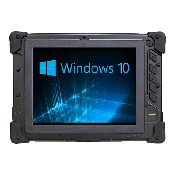
The Instructions Manual Front View of the Computer RFID Microphone 2M CCD Power button Barcode Trigger Hot key1 Hot key2 Hot key3 Hot key4 8” TFT Panel Status LED Fingerprint Brightness Rubber Corner Adjustment 8” inch TFT (1024x768) LCD Display with Touch Screen Control Panel: Data can be entered the computer module using the stylus pen or a soft/USB/wireless keyboard. - Page 23 CHAPTER 2 – System Overview RFID Device : The HF RFID Reader device is a communication device which includes complete circuits to achieve reading from and writing to the RFID tag. It conforms to various industry standard RF protocols of NFC. ...
- Page 24 The Instructions Manual Fingerprint: The device is virtually immune from attacking of fake finger. It can self-calibrate each sensor’s output signal for different skin conditions like sweaty, scarred and dry, to be an excellent image quality. The Brightness Adjustment On MCU-base programmable controller with capacitance sensors, the user can adjust the screen brightness with fingers directly.
-
Page 25: Right Side View Of The Computer
CHAPTER 2 – System Overview Right Side View of the Computer DC In RS-232 DC-in Jack: Plug the DC (Direct Current) end of the AC Adapter into this jack for external power and battery recharging. Before plugging in the power cord, you must first verify that the external power voltage is appropriate for your geographical area. -
Page 26: Left Side View Of The Computer
The Instructions Manual Left Side View of the Computer Network Micro SD Jack(RJ45) Mini Smart card Reader Mini Smart card Reader HDMI Strap Hook Network Jack (RJ45): Interfaces with an Ethernet 10/100/1000 Mbps Base-T network connection. HDMI : The High Definition Pictures can be transmitted to display from computer with the HDMI cable. -
Page 27: Bottom View Of The Computer
CHAPTER 2 – System Overview Bottom View of the Computer Docking Port Docking Port ﹕ The extended multi-function included: the battery charger port, the USB ports supporting most USB mouse and keyboard devices, RJ-45 Internet port, RS-232 port, DC-In Jack, Microphone and Headphone. -
Page 28: Top View Of The Computer
The Instructions Manual Top View of the Computer Barcode Scanner M.S.R Barcode Scanner: (optional) Omni directional bar code reading. Scan rate of up to 200 scans per second in linear emulation mode or 56 scans per second in Omni directional mode. Fully compatible with Intermec’s family of decoded engines. -
Page 29: Rear View Of The Computer
CHAPTER 2 – System Overview Rear View of the Computer Stylus Pen MMCX Connector Rear CMOS Camera Battery Switch Battery Lock Battery Pack Battery Indicator Battery Indicator Speaker Switch Stylus Pen: A stylus pen is used to activate the touch screen display and functions in the same way as an external mouse. - Page 30 The Instructions Manual GPS: (optional) Support 20-channel GP Rear CMOS Camera: (optional) The build-in 5M pixels CMOS camera module supports auto reverse function. Images can be captured and disseminated instantaneously. Internal Speakers: The computer’s built-in a single speaker support audio applications for all media software.
-
Page 31: Chapter 3
& & Chapter Preview: Caring for your Computer Configuring DRAM and SIM Card Adjusting the Resolutions for the Computer’s Display and an External Display... -
Page 32: Caring For Your Computer
The Instructions Manual Caring for Your Computer To guarantee a long life for the computer and to ensure it functions optimally, pay particular attention to the following recommended maintenance guidelines. Routine Care Follow these guidelines to keep the computer working properly: Do not attempt to disassemble or modify the computer in any way. -
Page 33: Caring For The Ac Adapter
CHAPTER 3 – Protecting & Maintaining Caring for the AC Adapter Be sure to only use the AC adapter that comes provided with this product or a compatible option from the manufacturer. Other adapters may cause damage to the computer and will not be covered under the warranty. Grasp the adapter plug and not the cord, when unplugging the adapter from an electrical outlet. -
Page 34: Configuring Dram And Sim Card
The Instructions Manual Configuring DRAM and SIM Card Configuring DRAM Remove these 5 screws on the Memory cover Remove the 1 screw and the Metal Cover Dismount the back stand. Configuring SIM Card Remove The Battery Pack Please insert the SIM Card to the slot ( Red Frame). -
Page 35: Adjusting The Video Resolution
CHAPTER 3 – Protecting & Maintaining Adjusting the Video Resolution Changing the Video Resolution of the Computer 1. Choose one of the two options to open the Display Properties dialog box: 1.1. Click the right button of the mouse on the desktop and select Properties from the menu. -
Page 36: Chapter 4
& & Chapter Preview: Specifications and Standard Features Software... -
Page 37: Specifications And Standard Features
CHAPTER 4 – Specifications & Software Specifications and Standard Features Processor INTEL Atom processor Dual Core N2600 1.6 GHZ Operating System ® Microsoft Window 7 ( Embedded / Professional ) Option: Linux System BIOS Phoenix BIOS Memory 1x204 pin DDR III SO-DIMM Socket support/ up to 2GB Display ... - Page 38 The Instructions Manual Wireless Connectivity Wireless LAN : IEEE 802.11b+g+n Bluetooth ® 3.5G Module WCDMA R99 : maximum data rate of 384 kbps HSDPA : Downlink Category 8 (7.2 Mbps) or 10 (14.4 Mbps) HSUPA : E-DCH data rates of up to 5.76 Mbps for 2 ms TTI (UE category 6) uplink GSM R99 : Supports CS SMS GPRS : CS schemes –...
- Page 39 CHAPTER 4 – Specifications & Software Fingerprint Sensor Scan Area: 9.6 mm x 0.2 mm Image size: 192 x 4 pixels Image resolution: 508 DPI Automatic image calibration Brightness Adjust by Slide S.W GPS (optional) Support 20-channel GPS Multimedia ...
- Page 40 The Instructions Manual Interface 2x USB 2.0 Ports Micro SD Card Port RS-232 Port HDMI Port Ethernet (RJ45) Microphone Build-in Speaker Docking Port DC Power In LED Status Indicators : HDD LED (Orange) Flashing – Disk Accessing Battery LED (Green) –...
-
Page 41: Software
CHAPTER 4 – Specifications & Software Software Using The Smart Panel to Calibrate The Screen Select the icon on the desktop to launch the Calibration program and the following panels will appear. Select Tool, then select 4 Point Calibration. A red flashing X will appear in the lower-left corner of the screen, then tap or click the X and hold it until the green X appears. -
Page 42: Using The Front Panel Hot Key Utility
The Instructions Manual Using The Front Panel Hot Key Utility Please refer to the following descriptions for each of all 5 hot keys. Key T : A dedicated button to enable / disable Barcode function. - Page 43 CHAPTER 4 – Specifications & Software Key 1: The defaulted key function is to launch “Windows Task Manager” application to manage your applications. The user is able to redefine the key function. Key 2: The defaulted key function is to launch “Cap Sound” application to enable / disable audio recorder.
- Page 44 The Instructions Manual Key 3: The defaulted key function is to launch “Windows Media Player” application to play music or video. The user is able to redefine the key function. Key 4: Press Key 4 to launch submenu function. The “submenu bar” as the following will be displayed on the desktop.
- Page 45 CHAPTER 4 – Specifications & Software The statuses of the communication capacities will be displayed on the submenu bar. Key 1, Key 2, Key 3 and Key 4 are endowed with different functions when the “submenu bar” was triggered. Please refer to the following descriptions. Click WiFi icon or press Key 1 to enable / disable the wireless function. Switch Click Bluetooth icon or press Key 2 to enable / disable the bluetooth function. Switch ...
-
Page 46: Define The Function For Hot Key Utility
The Instructions Manual Click 3G i con or press Key 3 to enable / disable the 3G function. Switch Click GPS i con or press Key 4 to enable / disable the GPS function. Switch Click OK icon or wait for 3 seconds to Exit. Define the Functions for Hot Key Utility Right‐click the “Hot Key” icon in the Windows system tray, then select “Define” to launch the “User Defined Function” application. ... - Page 47 CHAPTER 4 – Specifications & Software Type the correct path of the APP or browse the Folder icon to select your APP Click here select APP Make sure the defined APP path is correct. Your APP path Click “Save” to confirm your selections. ...
-
Page 48: Using The Bluetooth Utility, Bluesoleil
The Instructions Manual Using The Bluetooth Utility: BlueSoleil allows the computer to wirelessly access a variety of Bluetooth enabled digital devices, such as cameras, mobile phones, headsets, printers, and GPS receivers. Users can also create networks and exchange data with other Bluetooth enabled computers or PDAs. - Page 49 CHAPTER 4 – Specifications & Software Select “add device“ (Red Circle). Some blue tooth devices were found and listed out. Select “Blue tooth Keyboard“ or other devices. Type the number or password for configuration. Selected Blue tooth device has been successfully configured with the computer.
-
Page 50: Making A 3.5G Connection And Disconnection
The Instructions Manual Making a 3.5G Connection and Disconnection Select Start Menu -> All Programs -> Sync manager -> Connection Manager Utility -> Connection Manager to launch the program. The system will launch the program automatically after booting the computer. ... -
Page 51: Using The Cmos Camera
CHAPTER 4 – Specifications & Software Disconnection 1. Select <DISCONNECT> to terminate the connection. 2. Select <Yes> to confirm the disconnection. Using the CMOS Camera Select “ AMCAP” ICON Select “device“ and “USB Video device“. The first bar for the front camera and the second bar for the rear camera. -
Page 52: Using The Rfid
The Instructions Manual Using the RFID Select “Holy Stone” ICON Type “3” for the Select COM Port. Put your RFID card close to the RFID Sensor. The message “TAG = MIFARE 1K” will be displayed, if the computer accepts the RFID card. -
Page 53: Using The Minismart Card
CHAPTER 4 – Specifications & Software Using the Mini Smart Card Select the “Mini Smart” icon. Select the “ PC/SC ” button. Insert the Mini Smart Card into the slot and press the “Connect to Card” button. -
Page 54: Using The Barcode Scanner
The Instructions Manual The detail information will be displayed on the Result dialog box. Using the Bar code Scanner Select the “Opticon RL” icon. - Page 55 CHAPTER 4 – Specifications & Software 2.1 To selecte the " Settings 2.2 To selecte the " Com port " number. 2.3 To click " Toggle on/off ". The correct com port was selected and Port is open...
- Page 56 The Instructions Manual 4.1 To Calling " NotePad " 4.2 To Pressing the 【T】Function key. ( The scanner will be reading ) The readed data will in Notepad.
-
Page 57: Using The Msr
CHAPTER 4 – Specifications & Software Using the MSR Select the “NotePad” icon. Insert the Cash Card or ATM Card into the MSR slot. The information will be displayed on the screen. Using The GPS Please disable the Bar Code Scanner and follow the steps below. To Confirmed the GPS COM port number at the device manager. - Page 58 The Instructions Manual Select the “U-Center 6.01” ICON. Select COM3. Select the Baud Rate. Receive the Satellite Channel.
-
Page 59: Using The Brightness Adjust
CHAPTER 4 – Specifications & Software Using the Brightness Adjustment The user can adjust the screen brightness with fingers while the computer gets into the O.S. status. On the screen, to slide fingers from left to right or right to left to change the screen brightness. -
Page 60: Using The Fingerprint
The Instructions Manual Using the Fingerprint Function Click the delta icon in the Windows system tray, then Click Fingerprint icon (BioExcess) - Page 61 CHAPTER 4 – Specifications & Software Select “ Initial Wizard “ bar Click 【Next】...
- Page 62 The Instructions Manual To swipe your finger on the fingerprint device for the enrollment. Repeat 2 times.
Need help?
Do you have a question about the RMI80-D and is the answer not in the manual?
Questions and answers