Table of Contents
Advertisement
This service information is designed for experienced repair technicians only and is not designed for use by the general public.
It does not contain warnings or cautions to advise non-technical individuals of potential dangers in attempting to service a product.
Products powered by electricity should be serviced or repaired only by experienced professional technicians. Any attempt to service
or repair the products dealt with in this service information by anyone else could result in serious injury or death.
There are special components used in this equipment which are important for safety. These parts are marked by
Diagrams, Circuit Board Diagrams, Exploded Views and Replacement Parts List. It is essential that these critical parts should be replaced
with manufacturer's specified parts to prevent shock, fire or other hazards. Do not modify the original design without permission of
manufacturer.
In order to avoid frostbite, be assured of no refrigerant leakage during the installation or repairing of refrigerant circuit.
R32 REFRIGERANT
– This Air Conditioner contains and operates with refrigerant R32.
THIS PRODUCT MUST ONLY BE INSTALLED OR SERVICED BY QUALIFIED PERSONNEL.
Refer to Commonwealth, State, Territory and local legislation, regulations, codes, installation & operation manuals, before the
installation, maintenance and/or service of this product.
CS-Z25UD3RAW
CS-Z35UD3RAW
CS-Z50UD3RAW
CS-Z60UD3RAW
Panasonic
WARNING
IMPORTANT SAFETY NOTICE
PRECAUTION OF LOW TEMPERATURE
CAUTION
Order No: PAPAMY1903104CE
Indoor Unit
© Panasonic Corporation 2019.
Outdoor Unit
CU-Z25UBRA
CU-Z35UBRA
CU-Z50UBRA
CU-Z60UBRA
Destination
Australia
New Zealand
in the Schematic
Advertisement
Table of Contents

Related Manuals for Panasonic CS-Z35UD3RAW


Summary of Contents for Panasonic CS-Z35UD3RAW
- Page 1 – This Air Conditioner contains and operates with refrigerant R32. THIS PRODUCT MUST ONLY BE INSTALLED OR SERVICED BY QUALIFIED PERSONNEL. Refer to Commonwealth, State, Territory and local legislation, regulations, codes, installation & operation manuals, before the installation, maintenance and/or service of this product. © Panasonic Corporation 2019.
-
Page 2: Table Of Contents
15.7 Auto Restart Control ........90 CS-Z25UD3RAW CU-Z25UBRA 15.8 Indication Panel ..........90 CS-Z35UD3RAW CU-Z35UBRA ....31 Protection Control ..........91 CS-Z50UD3RAW CU-Z50UBRA 16.1 Protection Control for All Operations ..91 CS-Z60UD3RAW CU-Z60UBRA ....32 ... -
Page 3: Safety Precautions
1. Safety Precautions Read the following “SAFETY PRECAUTIONS” carefully before perform any servicing. Confirm the type of gas used before installation. Electrical work must be installed or serviced by a licensed electrician. Be sure to use the correct rating of the power plug and main circuit for the model to be installed. - Page 4 WARNING For R410A/R32 model, use piping, flare nut and tools which is specified for R32 refrigerant. Using of existing (R22) piping, flare nut and tools may cause abnormally high pressure in the refrigerant cycle (piping), and possibly result in explosion and injury. ...
- Page 5 CAUTION Do not touch the sharp aluminium fin, sharp parts may cause injury. Carry out drainage piping as mentioned in installation instructions. If drainage is not perfect, water may enter the room and damage the furniture. Select an installation location which is easy for maintenance. Incorrect installation, service or repair of this air conditioner may increase the risk of rupture and this may result in loss damage or injury and/or property.
-
Page 6: Precaution For Using R32 Refrigerant
2. Precaution for Using R32 Refrigerant The basic installation work procedures are the same as conventional refrigerant (R410A, R22) models. However, pay careful attention to the following points: WARNING The appliance shall be stored, installed and operated in a well ventilated room with indoor floor area larger than A ) [refer Table A] and without any continuously operating ignition source. - Page 7 CAUTION Installation (Space) Must ensure the installation of pipe-work shall be kept to a minimum. Avoid use dented pipe and do not allow acute bending. Must ensure that pipe-work shall be protected from physical damage. Must comply with national gas regulations, state municipal rules and legislation. Notify relevant authorities in accordance with all applicable regulations.
- Page 8 CAUTION 2-5. No ignition sources No person carrying out work in relation to a refrigeration system which involves exposing any pipe work that contains or has contained flammable refrigerant shall use any sources of ignition in such a manner that it may lead to the risk of fire or explosion. He/She must not be smoking when carrying out such work.
- Page 9 CAUTION The following leak detection methods are deemed acceptable for all refrigerant systems. No leaks shall be detected when using detection equipment with a capability of 10 Pa•m /s or better, for example, a helium sniffer. Electronic leak detectors may be used to detect flammable refrigerants, but the sensitivity may not be adequate, or may need re- calibration.
- Page 10 CAUTION Labelling Equipment shall be labelled stating that it has been de-commissioned and emptied of refrigerant. The label shall be dated and signed. Ensure that there are labels on the equipment stating the equipment contains flammable refrigerant. Recovery ...
-
Page 11: Specifications
3. Specifications Model CS-Z25UD3RAW Indoor POS (EAN) 5025232886913 Model CU-Z25UBRA Outdoor POS (EAN) 5025232885466 Performance Test Condition Phase, Hz Single, 50 Power Supply Min. Mid. Max. Min. Mid. Max. 0.85 2.60 3.20 0.85 2.60 3.20 Capacity BTU/h 2900 8870 10900 2900 8870 10900... - Page 12 Model CS-Z25UD3RAW Indoor POS (EAN) 5025232886913 Model CU-Z25UBRA Outdoor POS (EAN) 5025232885466 Type Sirocco Material PP GFZ010A / GF20% Motor Type DC / Transistor (8-poles) Input Power – Output Power Cool Heat Cool Heat Cool Speed Heat Cool 1100 Heat 1100 Cool 1150...
- Page 13 Model CS-Z25UD3RAW Indoor POS (EAN) 5025232886913 Model CU-Z25UBRA Outdoor POS (EAN) 5025232885466 Stacking No. (CS / CU / CZ) Actual Stacking Quantity (14 / 6 / – ) Pipe Diameter (Liquid / Gas) mm (inch) 6.35 (1/4) / 9.52 (3/8) Standard length m (ft) 5.0 (16.4)
- Page 14 Model CS-Z35UD3RAW Indoor POS (EAN) 5025232886920 Model CU-Z35UBRA Outdoor POS (EAN) 5025232885473 Performance Test Condition Phase, Hz Single, 50 Power Supply Min. Mid. Max. Min. Mid. Max. 0.85 3.70 4.00 0.85 3.70 4.00 Capacity BTU/h 2900 12600 13600 2900 12600...
- Page 15 Model CS-Z35UD3RAW Indoor POS (EAN) 5025232886920 Model CU-Z35UBRA Outdoor POS (EAN) 5025232885473 Type Sirocco Material PP GFZ010A / GF20% Motor Type DC / Transistor (8-poles) Input Power – Output Power Cool Heat Cool Heat Cool 1010 Speed Heat 1000 Cool...
- Page 16 Model CS-Z35UD3RAW Indoor POS (EAN) 5025232886920 Model CU-Z35UBRA Outdoor POS (EAN) 5025232885473 Stacking No. (CS / CU / CZ) Actual Stacking Quantity (14 / 6 / – ) Pipe Diameter (Liquid / Gas) mm (inch) 6.35 (1/4) / 9.52 (3/8)
- Page 17 Model CS-Z50UD3RAW Indoor POS (EAN) 5025232886937 Model CU-Z50UBRA Outdoor POS (EAN) 5025232885480 Performance Test Condition Phase, Hz Single, 50 Power Supply Min. Mid. Max. Min. Mid. Max. 0.90 5.00 5.70 0.90 5.00 5.70 Capacity BTU/h 3070 17100 19400 3070 17100 19400 kcal/h 4300...
- Page 18 Model CS-Z50UD3RAW Indoor POS (EAN) 5025232886937 Model CU-Z50UBRA Outdoor POS (EAN) 5025232885480 Type Sirocco Material PP GFZ010A / GF20% Motor Type DC / Transistor (8-poles) Input Power – Output Power Cool Heat Cool Heat Cool 1190 Speed Heat 1210 Cool 1440 Heat 1440...
- Page 19 Model CS-Z50UD3RAW Indoor POS (EAN) 5025232886937 Model CU-Z50UBRA Outdoor POS (EAN) 5025232885480 Stacking No. (CS / CU / CZ) Actual Stacking Quantity (14 / 4 / – ) Pipe Diameter (Liquid / Gas) mm (inch) 6.35 (1/4) / 12.70 (1/2) Standard length m (ft) 5.0 (16.4)
- Page 20 Model CS-Z60UD3RAW Indoor POS (EAN) 5025232886944 Model CU-Z60UBRA Outdoor POS (EAN) 5025232886999 Performance Test Condition Phase, Hz Single, 50 Power Supply Min. Mid. Max. Min. Mid. Max. 0.90 5.60 6.50 0.90 5.60 6.50 Capacity BTU/h 3070 19100 22200 3070 19100 22200 kcal/h 4820...
- Page 21 Model CS-Z60UD3RAW Indoor POS (EAN) 5025232886944 Model CU-Z60UBRA Outdoor POS (EAN) 5025232886999 Type Sirocco Material PP GFZ010A / GF20% Motor Type DC / Transistor (8-poles) Input Power – Output Power Cool Heat Cool Heat 1000 Cool 1230 Speed Heat 1240 Cool 1480 Heat...
- Page 22 Model CS-Z60UD3RAW Indoor POS (EAN) 5025232886944 Model CU-Z60UBRA Outdoor POS (EAN) 5025232886999 Stacking No. (CS / CU / CZ) Actual Stacking Quantity (14 / 4 / – ) Pipe Diameter (Liquid / Gas) mm (inch) 6.35 (1/4) / 12.70 (1/2) Standard length m (ft) 5.0 (16.4)
- Page 23 Example: The indoor units’ combination below is possible to connect to CU-3Z54VBR. (Total nominal capacity of indoor units is between 4.5kW to 9.5kW) 1) Two CS-Z35UD3RAW only. (Total nominal cooling capacity is 7.0kW) Remarks for CU-4Z71VBR 1. At least two indoor units must be connected.
- Page 24 ● ● ● ● ● ● CS-RZ25VKRW 2.5kW CS-Z25UD3RAW ● ● ● ● ● ● ● ● ● CS-Z25UB4RAW CS-RZ35VKRW CS-Z35UD3RAW 3.5kW ● ● ● ● ● ● ● ● ● CS-Z35UB4RAW 4.2kW CS-RZ42VKRW – – ● ● ● ●...
-
Page 25: Features
4. Features Inverter Technology Wider output power range Energy saving Quick Cooling Quick Heating More precise temperature control Environment Protection Non-ozone depletion substances refrigerant (R32) Long Installation Piping Long piping up to 20 meters (1.0 ~ 1. 5HP) and 30 meters (2.0 ~ 2.25HP) during single split connection only ... -
Page 26: Location Of Controls And Components
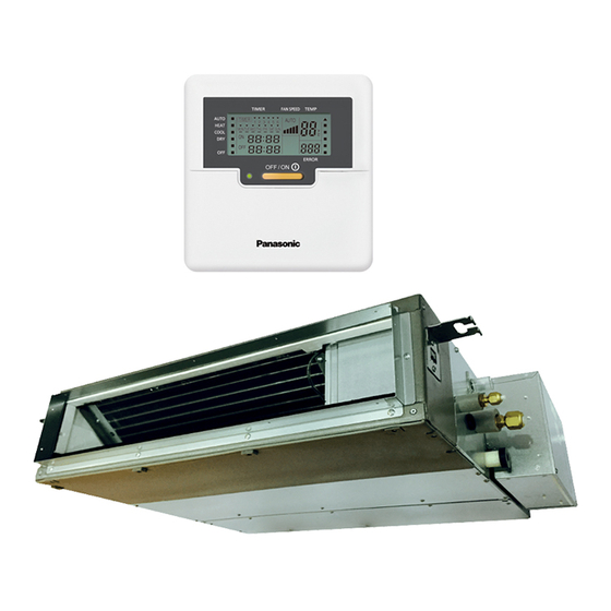
5. Location of Controls and Components Indoor Unit Air inlet Air outlet Outdoor Unit Remote Control Timer/Clock Setting Display Fan Speed Display Temperature Setting Display Quiet Operation Indicator Operation Mode Selection Powerful Operation Indicator Indicator System Error Display OFF Indicator OFF/ON Button OFF / ON Operation LED... -
Page 27: Dimensions
Indoor Unit <Front View> (AIR OUTLET DUCT FLANGE) <Top View> <Side View> 160 × 4 = 640 <Side View> WATER INLET DRAIN PORT (UPPER & LOWER) <Back View> <Remote Control> <Remote control transmitter> 15.5 (AIR INLET) AIR FILTER Panasonic Unit: mm... -
Page 28: Outdoor Unit
Outdoor Unit 6.2.1 CU-Z25UBRA <Top View> Space necessary for installation 67.6 (104.7) 570.3 104.9 60.5 100 mm 100 mm 1000 mm 2-way valve at Liquid side Anchor Bolt Pitch (High Pressure) × 3-way valve at Gas side (Low Pressure) <Side View> <Side View>... - Page 29 6.2.2 CU-Z35UBRA <Top View> Space necessary for 68.7 installation (124) (62.6) 100 mm 100 mm 1000 mm Anchor Bolt Pitch 330 × 540 <Side View> <Side View> <Front View> 3-way valve at Gas side Unit : mm (Low Pressure) 2-way valve at Liquid side (High Pressure) <Chassis>...
- Page 30 6.2.3 CU-Z50UBRA CU-Z60UBRA <Top View> Space necessary for installation (131) 34.7 100 mm 100 mm 1000 mm Anchor Bolt Pitch 360.5 × 613 2-way valve at Liquid side (High Pressure) 3-way valve at Gas side (Low Pressure) <Front View> <Side View> <Side View>...
-
Page 31: Refrigeration Cycle Diagram
7. Refrigeration Cycle Diagram CS-Z25UD3RAW CU-Z25UBRA CS-Z35UD3RAW CU-Z35UBRA INDOOR OUTDOOR LIQUID EXPANSION TEMP. SIDE STRAINER VALVE STRAINER SENSOR 2-WAY VALVE PIPE TEMP. INTAKE SENSOR 2 TEMP. SENSOR CONDENSER PIPE TEMP. PIPE SENSOR 1 TEMP. SENSOR HEAT EXCHANGER (EVAPORATOR) SIDE RECEIVER... -
Page 32: Cs-Z50Ud3Raw Cu-Z50Ubra Cs-Z60Ud3Raw Cu-Z60Ubra
CS-Z50UD3RAW CU-Z50UBRA CS-Z60UD3RAW CU-Z60UBRA INDOOR OUTDOOR LIQUID EXPANSION SIDE STRAINER VALVE 2-WAY PROCESS VALVE TUBE TEMP. PIPE SENSOR TEMP. CONDENSER INTAKE SENSOR 2 TEMP. SENSOR PIPE TEMP. PIPE SENSOR 1 TEMP. SENSOR HEAT EXCHANGER (EVAPORATOR) SIDE 4-WAYS VALVE 3-WAY RECEIVER VALVE TANK SENSOR... -
Page 33: Block Diagram
8. Block Diagram... -
Page 34: Wiring Connection Diagram
9. Wiring Connection Diagram Indoor Unit... -
Page 35: Outdoor Unit
Outdoor Unit 9.2.1 CU-Z25UBRA YELLOW (YEL) OR T(W) REMARKS BLU : BLUE BLK : BLACK SINGLE PHASE POWER SUPPLY TO INDOOR UNIT WHT : WHITE RED : RED BLUE YLW : YELLOW (RED) (BLU) GRY : GRAY OR R(U) OR S(V) GRN : GREEN TERMINAL TRADEMARK... - Page 36 9.2.2 CU-Z35UBRA YELLOW (YEL) OR T(W) REMARKS BLU : BLUE BLK : BLACK SINGLE PHASE POWER SUPPLY TO INDOOR UNIT WHT : WHITE RED : RED BLUE YLW : YELLOW (RED) (BLU) GRY : GRAY OR R(U) OR S(V) GRN : GREEN TERMINAL TRADEMARK PNK : PINK...
- Page 37 9.2.3 CU-Z50UBRA CU-Z60UBRA YELLOW (YEL) OR T(W) REMARKS BLU : BLUE BLK : BLACK SINGLE PHASE POWER SUPPLY TO INDOOR UNIT WHT : WHITE RED : RED BLUE YLW : YELLOW (RED) (BLU) GRY : GRAY OR R(U) OR S(V) GRN : GREEN TERMINAL TRADEMARK...
-
Page 38: Electronic Circuit Diagram
10. Electronic Circuit Diagram 10.1 Indoor Unit... -
Page 39: Outdoor Unit
10.2 Outdoor Unit 10.2.1 CU-Z25UBRA REACTOR RAT1 RAT2 (GRY) (GRY) 15.8k 220u SINGLE PHASE POWER SUPPLY TO INDOOR UNIT OUTDOOR AIR TEMP. SENSOR (THERMISTOR) t° TERMINAL CN–TH1 t° BOARD (WHT) PIPING TEMP. SENSOR (THERMISTOR) DATA t° (RED) COMPRESSOR TEMP. SENSOR (THERMISTOR) COMMUNICATION CN–TANK CIRCUIT... - Page 40 10.2.2 CU-Z35UBRA REACTOR RAT1 RAT2 (GRY) (GRY) 15.8k 220u SINGLE PHASE POWER SUPPLY TO INDOOR UNIT OUTDOOR AIR TEMP. SENSOR (THERMISTOR) t° TERMINAL CN–TH1 t° BOARD (WHT) PIPING TEMP. SENSOR (THERMISTOR) DATA t° (RED) COMPRESSOR TEMP. SENSOR (THERMISTOR) COMMUNICATION CN–TANK CIRCUIT 4.99k FUSE 2...
- Page 41 10.2.3 CU-Z50UBRA CU-Z60UBRA REACTOR RAT2 RAT1 (GRY) (GRY) 15.8k 220u SINGLE PHASE POWER SUPPLY TO INDOOR UNIT OUTDOOR AIR TEMP. SENSOR (THERMISTOR) t° TERMINAL CN–TH1 t° BOARD (WHT) PIPING TEMP. SENSOR (THERMISTOR) DATA t° (RED) COMPRESSOR TEMP. SENSOR (THERMISTOR) COMMUNICATION CN–TANK CIRCUIT 4.99k...
-
Page 42: Printed Circuit Board
11. Printed Circuit Board 11.1 Indoor Unit 11.1.1 Main Printed Circuit Board CN-T1 CN-AC CN-T2 CN-DRMTR1 JP10 (Random Auto Restart enable/disable) CN-FM CN-TH HAJEM-A CN-CNT CN-FSW CN-DISP... -
Page 43: Outdoor Unit
11.2 Outdoor Unit 11.2.1 Main Printed Circuit Board POWER TRANSISTOR (IPM) CN-MTR2 CN-MTR1 CN-TH1 CN-DEMAND CN-TANK CN-HOT CN-STM AC-WHT DATA CURRENT TRANSFORMER (CT) AC-BLK CN-V1... - Page 44 11.2.2 Demand Control Printed Circuit Board CN-DEMAND CN-OPT CN-PWR AC_GND...
-
Page 45: Installation Instruction
12. Installation Instruction ■ Required Materials Insulation of piping connections Read the catalog and other technical materials • Carry out insulation after and prepare the required materials. checking for gas leaks and secure with vinyl tape. Applicable piping kit Vinyl tape Piping size Applicable piping kit... -
Page 46: Indoor Unit
12.1 Indoor Unit 12.1.1 Selecting the Installation Location Take into consideration the following contents when creating the blueprint. ■ Indoor unit installation location Do not install the unit in excessive oil fume area such as kitchen, workshop and etc. ... - Page 47 12.1.3 Installing the Indoor Unit (Installation Embedded in the Ceiling) 12.1.3.1 Preparation before installation Always provide sufficient entry and exit space to allow installation work, inspection and unit replacement. Waterproof the rear surface of the ceiling below the unit in consideration of water droplets forming and dropping. CAUTION When cooling operation is performed for an extended period under the following conditions, water droplets may form and drop.
- Page 48 Dimension of the indoor unit 692 (Flange for air outlet duct) 640 (160x4) 2-ø3.1(Hole) 5-ø3.1(Hole) Inspection access (450x450) (Field supply) 824 (Suspension bolt pitch) 10-ø3.1(Hole) * Filter Uninstalled In case of Bottom Intake Dummy hole Air intake Remove the frame filter assy as shown in Cover plate diagram 1 Remove cover plate as shown in diagram 1...
- Page 49 Ceiling Opening Install inspection opening (450 mm x 450 mm) on the control box side where maintenance and inspection of the control box and drain pump are easy. Install another inspection opening (800 mm x 700 mm) also at the lower part of the unit.
- Page 50 Installation into the Ceiling Attach the nuts and washers to the hanging bolts, then lift up and hook the main unit onto the hanging fixtures. Check if the unit is leveled using a level or a vinyl hose filled partially with water. Hanging bolt (M10) (locally purchased) Flat...
- Page 51 Embed an outlet box (JIS C 8336) into the wall. Outlet box maybe purchased separately. Medium size square outlet box (obtain locally) Part No. DS3744 (Panasonic Co., Ltd.) or equivalent. Secure the remote controller lower case to the outlet box with the two accessory screws 3. Make sure that the lower case is flat againts the wall at this time, with no bending.
- Page 52 12.1.4 Connecting the Drain Piping Lay the drain piping so as to ensure drainage. Use a locally purchased VP20 general rigid PVC pipe (outer diameter ø26) for the drain piping and firmly connect the indoor unit and the drain piping using supplied hose band to ensure that no leakage occurs. ...
- Page 53 12.1.6 Connecting the Indoor/Outdoor Connection Cable Remove the control box cover and insert the Ensure the colour of wires of outdoor unit and the connection cable into the control box. terminal Nos. are the same to the indoor’s ...
- Page 54 12.1.6.1 Wire Stripping and Connecting Requirement Wire stripping Conductor not Conductor Conductor fully inserted fully inserted over inserted Indoor/outdoor connection terminal board 5 mm or more No loose strand ACCEPT PROHIBITED PROHIBITED (gap between wires) when inserted Do not joint wires WARNING RISK OF FIRE JOINING OF WIRES MAY CAUSE...
- Page 55 12.1.7.2 Connecting the Piping to Outdoor Decide piping length and then cut by using pipe cutter. Do not overtighten, overtightening may cause gas leakage. Remove burrs from cut edge. Make flare after Piping size Torque inserting the flare nut (locate at valve) onto the copper pipe.
- Page 56 12.1.8 Switching the High State Switch (SW2) To increase the air volume, open the control box and on the control board, switch the FAN switch (SW2) to “HI”. See the diagram for “Connecting the Indoor/Outdoor Connection Cable”. 12.1.9 Note: Enabling long-range remote control ...
-
Page 57: Outdoor Unit
12.2 Outdoor Unit 12.2.1 Select the Best Location If an awning is built over the unit to prevent direct sunlight or rain, be careful that heat radiation from the condenser is not obstructed. There should not be any animal or plant which could be affected by hot air discharged. ... - Page 58 12.2.2 Install the Outdoor Unit After selecting the best location, start installation according to Indoor/Outdoor Unit Installation Diagram. Fix the unit on concrete or rigid frame firmly and horizontally by bolt nut (ø10 mm). When installing at roof, please consider strong wind and earthquake. Please fasten the installation stand firmly with bolt or nails.
- Page 59 AIR PURGING METHOD IS PROHIBITED FOR R32 SYSTEM 12.2.4 Air Tightness Test on the Refrigerating System Do not purge the air with refrigerants but use a vacuum pump to vacuum the installation. There is no extra refrigerant in the outdoor unit for air purging. ...
- Page 60 12.2.5 Connect the Cable to the Outdoor Unit (FOR DETAIL REFER TO WIRING DIAGRAM AT UNIT) Remove the control board cover from the unit by loosening the screw. Cable connection to the power supply through Isolating Devices (Disconnecting means). Connect the approved polychloroprene sheathed power supply cord 3 x 1.5 mm (1.0 ~ 1.5HP) or 3 x 2.5 mm (2.0 ~ 2.25HP), type designation 60245 IEC 57 or heavier cord to the terminal board, and...
- Page 61 12.2.6 Piping Insulation Please carry out insulation at pipe connection portion as mentioned in Indoor/Outdoor Unit Installation Diagram. Please wrap the insulated piping end to prevent water from going inside the piping. If drain hose or connecting piping is in the room (where dew may form), please increase the insulation by using POLY-E FOAM with thickness 6 mm or above.
-
Page 62: Installation And Servicing Air Conditioner Using R32
13. Installation and Servicing Air Conditioner using R32 13.1 About R32 Refrigerant For air conditioning refrigerants such as R410A, the refrigerants were collected back in order to prevent their air dissipation, to curbe the global warming impact, in case they were released into the atmosphere. In the “4th Environmental Basic Plan”, 80% reduction of greenhouse gas emissions by 2050 is required, and due to this requirement, further reduction in the emission of high greenhouse effect gas, such as CFCs, is required. - Page 63 2. Characteristic of Pressure As shown in Table 2, R32 does not have much difference in vapor pressure at the same refrigerant temperature comparing to R410A, but comparing to R22, it is higher at 1.6 times more. Thus, the same as in case of R410A, it is necessary to do installation and service using high-pressure tools and components.
-
Page 64: Refrigerant Piping Installation • Tools Used In Services
13.3 Refrigerant piping installation • Tools used in services 13.3.1 Required Tools R32 refrigerant air conditioners use the common parts as R410A air conditioners for two-way valves and three-way valves (diameters of service ports); thus, they maintain commonality in the maintenance of the compressive strength, the size of pipe flaring, and the size of flare nuts as R410A. - Page 65 3. Torque wrenches (diameters 1/2, 5/8) Manifold gauges / Charging hoses In order to strengthen the compressive strength, the diameters of wrenches change depending on the flare nut sizes. Torque wrenches Differences in charging hoses Differences in torque wrenches (common R410A) Normal 5.1 MPa 3.4 MPa...
- Page 66 7. HFC refrigerant_Electric gas leakage tester 9. Refrigerant cylinders R32 refrigerant is often used for other mixed Refrigerant cylinders for R410A are painted in pink, refrigerant (R410A, R404A, R407C etc.). Therefore, and the ones for R32 are painted in other colors that the usage of existing HFC detectors is possible, but in might subject to change according to the international order to detect more accurately, we recommend to...
- Page 67 11. Tools used for refrigerant piping installations and services Tools for R410A Common with R32 Possibility of usage for R22 ○ ○ Pipe cutters, reamers or scrapers ○ ○ Flare tools (clutch type) ○ ○ Torque wrench (1/4, 3/8) ○ ×...
-
Page 68: New Installation, Relocation, Repairing Of Refrigerant Cycle System The Procedures
13.4 New installation, Relocation, Repairing of Refrigerant Cycle System The Procedures Relocation Repairing refrigerant cycle Installation Indoor / outdoor units and piping Pump down Refrigerant recovery • Displacing pipes and wires, and displacing indoor / outdoor units Prevention of impurity •... -
Page 69: Piping Installation Of R32
13.5 Piping installation of R32 13.5.1 Pipe materials used and flaring Copper pipes are used for refrigerant piping. Pipes Pipe thickness which comply with JIS Regulations need to be used. Room air conditioners which use R410A and R32 O and OL materials Thickness (mm) have higher pressure;... -
Page 70: Installation, Relocation, And Service
13.6 Installation, Relocation, and Service 13.6.1 Air purge and gas leak test for new installation (using new refrigerant pipes) using vacuum pump (From the point of view of global environment protection, do not release CFCs into the atmosphere during installation work) 1. - Page 71 13.6.2 Process of refrigerant recovery 1. Connect the center charging hose of manifold gauge to the in-let side of recovery device. 2. Connect the valves of the discharge side of recovery device and liquid side of refrigerant cylinder with red hose (charging hose).
- Page 72 13.6.3 Relocation 1. Removing the air conditioning unit a) Recovery of outdoor unit refrigerant by pumping down Press “forced cooling button” (as a general rule, since 1998 the name of cooling testing button is changed, and this name is unified within the air conditioning industry), and then you are able to start cooling operation in which the room temperature is low, and you can recover the refrigerant from the outdoor unit.
- Page 73 13.6.6 Re-insertion of refrigerant in service When re-insertion is needed, follow the procedures to ensure the insertion of new refrigerant at correct amount. 1. Attach charging hose (blue) to the service port of the outdoor unit. 2. Attach charging hose (red) to the vacuum pump. Fully open the 2-way and 3-way valves. 3.
-
Page 74: Repairing Of Refrigerant Cycle / Brazing Point
13.7 Repairing of refrigerant cycle / Brazing point 13.7.1 Preparation for repairing of refrigerant cycle / brazing Brazing which is a technique needed for repairing refrigerant cycle requires advanced technique and experience, and this brazing procedure can only be performed by the workers who completed “Gas Welding Skill Training” regulated by the Occupational Safety and Health Act, and went through the training programs of refrigerant operations. - Page 75 2. Cylinder without adjustment valve side gauge pressure is adjusted by the adjuster. Check the both side valves of the torch and open the cylinder valve to check the remaining refrigerant in the cylinder. Caution: Do not attach oil component on the connection port of the adjuster. Especially, use an oxygen cylinder adjuster which is no oil substance type.
- Page 76 13.7.5 Types of flame Types of flame change based on the proportion of propane and oxygen. [Neutral Flame] Perform brazing with this flame (This is a flame when oxygen and propane are mixed at proper proportion, and has lesser effect on the brazed metals) White core flame 10 ~ 15 mm...
- Page 77 13.7.7 Selection of brazing material Use BAg brazing material (silver solder) to increase the welding performance. Tensile strength Composition of ingredients (%) Temperature (°C) Characteristics (Reference) Category Standard Brazing Base Number Solidus Liquidus Kgf•cm applications temp material Liquidity is good at low temperature, 49.0 14.5...
- Page 78 13.7.10 Checking of brazing (insert) points 1. No impurity on the brazing point Gap 0.025 ~ 0.05 mm If dirt or oil is attached on the brazing point, the brazing filler metal does not reach to junction, and Inner diameter ø6.45 it may cause poor welding.
- Page 79 (Reference) Melting temperature of copper • • • • • • • Approx. 1083°C Maximum temperature obtained in propane and oxygen • • • • • • • Approx. 1083°C The important point is to heat the bonding part uniformly within a short period of time until reaching to the brazing temperature in the following manner.
-
Page 80: Reference> Analysis Method For No Error Code, No Cooling / No Warming
13.8 <Reference> Analysis method for no error code, no cooling / no warming 13.8.1 Preparation for appropriate diagnosis In order to obtain appropriate operation characteristics, minimum 15 minutes or more operation time [testing operation (rated operation)] is required. 1. Method of rated operation (rated operation) For the models which have two buttons of “emergency operation and forced cooling operation”, press forced cooling button once. - Page 81 1. Measuring temperature 1) Indoor unit suction temperature, release temperature, temperature difference, → Measure by thermometer 2) 2-way valve pipe temperature in cooling mode is low temperature (benchmark:5 ~ 10°C), in heating mode is medium temperature (benchmark:25 ~ 35°C). 3) 3-way valve pipe temperature in cooling mode is low temperature (benchmark:7 ~ 15°C) in heating mode is high temperature (benchmark:38 ~ 50°C).
-
Page 82: Operation And Control
14. Operation and Control 14.1 Basic Function Inverter control, which equipped with a microcomputer in determining the most suitable operating mode as time passes, automatically adjusts output power for maximum comfort always. In order to achieve the suitable operating mode, the microcomputer maintains the set temperature by measuring the temperature of the environment and performing temperature shifting. - Page 83 14.1.4 Heating Operation 14.1.4.1 Thermostat control Compressor is OFF when Intake Air Temperature - Internal Setting Temperate > +2.0°C. Compressor is ON after waiting for 3 minutes, if the Intake Air Temperature - Internal Setting Temperature < Compressor OFF point. 14.1.5 Automatic Operation ...
- Page 84 The indoor fan will operate according to pattern below. [Heating] According to indoor pipe temperature, automatic heating fan speed is determined as follows. B. Feedback control Immediately after the fan motor started, feedback control is performed once every second. ...
-
Page 85: Quiet Operation (Cooling Mode/Cooling Area Of Soft Dry Mode)
14.2 Quiet Operation (Cooling Mode/Cooling Area of Soft Dry Mode) A. Purpose To provide quiet cooling operation compare to normal operation. B. Control condition a. Quiet operation start condition When “quiet” button at remote control is pressed. b. Quiet operation stop condition When one of the following conditions is satisfied, quiet operation stops: Powerful button is pressed. -
Page 86: Powerful Mode Operation
14.3 Powerful Mode Operation When the powerful mode is selected, the internal setting temperature will shift higher up to +6.0°C (for Heating) or lower up to 4°C (for Cooling/Soft Dry) than remote control setting temperature for 20 minutes to achieve the setting temperature quickly. -
Page 87: Ha Terminal (Hajem-A)
14.7 HA Terminal (HAJEM-A) Enable digital connection from indoor unit to external devices. Control items: Start/stop input. Start/stop signal output. 200~300msec ON/OFF input (Pin 1-2) Monitor output (Pin 3-4) Unit condition Condition 1-2 (Pulse input): Unit ON/OFF condition switching with a pulse signal. (1 pulse signal: shortage status 200~300msec) 3-4 (Static output): 5V output during the unit ON. -
Page 88: Drain Pump Control
14.8 Drain Pump Control This unit has built-in with drain pump. Control content During COOL/DRY mode. During COOL/DRY mode, drain pump starts 10 seconds after indoor fan motor starts. The drain pump turns ON and turns OFF periodically. (ON or OFF duration depends on room temperature). ... -
Page 89: Operation Control (For Multi Split Connection)
15. Operation Control (For Multi Split Connection) During multi split connection, indoor unit’s operation controls are same with single split connection unless specified in this chapter. 15.1 Cooling operation 15.1.1 Thermostat control Capability supply to indoor unit is OFF (Expansion valve closed) when Intake Air Temperature — Internal setting temperature <... -
Page 90: Automatic Operation
15.4 Automatic Operation This mode can be set using remote control and the operation is decided by remote control setting temperature, remote control operation mode, indoor intake and outdoor air temperature. During operation mode judgment, indoor fan motor (with speed of -Lo) and outdoor fan motor are running for 30 seconds to detect the indoor intake and outdoor air temperature. -
Page 91: Protection Control
16. Protection Control 16.1 Protection Control for All Operations 16.1.1 Restart Control (Time Delay Safety Control) The Compressor will not turn on within 3 minutes from the moment operation stops, although the unit is turned on again by pressing OFF/ON button at remote control within this period. ... - Page 92 16.1.4 Compressor Overheating Prevention Control Instructed frequency for compressor operation will be regulated by compressor temperature. The changes of frequency are as below. If compressor temperature exceeds 103°C, compressor will be stopped, occurs 4 times per 20 minutes (“F97”...
-
Page 93: Protection Control For Cooling & Soft Dry Operation
16.2 Protection Control for Cooling & Soft Dry Operation 16.2.1 Outdoor Air Temperature Control The compressor operating frequency is regulated in accordance to the outdoor air temperature as shown in the diagram below. This control will begin 1 minute after the compressor starts. ... -
Page 94: Protection Control For Heating Operation
16.2.5 Dew Prevention Control 1 To prevent dew formation at indoor unit discharge area. This control will be activated if: Outdoor air temperature and Indoor pipe temperature judgment by microcontroller is fulfilled. When Cooling or Dry mode is operated more than 20 minutes or more. ... - Page 95 16.3.3 Overload Protection Control The compressor operating frequency is regulated in accordance to indoor heat exchanger temperature as shown below. If the heat exchanger temperature exceeds 60°C, compressor will stop. 16.3.4 Low Temperature Compressor Oil Return Control In heating operation, if the outdoor temperature falls below -10°C when compressor starts, the compressor frequency will be regulated up to 600 seconds.
-
Page 96: Servicing Mode
17. Servicing Mode 17.1 TEST RUN OPERATION (FOR PUMP DOWN/SERVICING PURPOSE) The Test Run operation will be activated by short-circuiting CN-S (Pin 1 & 2) at outdoor unit PCB after power supplied to outdoor unit terminal 1 and 2. The unit forced to run rated frequency cooling operation mode. POWER TRANSISTOR (IPM) -
Page 97: Troubleshooting Guide
18. Troubleshooting Guide 18.1 Refrigeration Cycle System In order to diagnose malfunctions, make sure that there are no Normal Pressure and Outlet Air Temperature (Standard) electrical problems before inspecting the refrigeration cycle. Gas Pressure Outlet air Temperature Such problems include insufficient insulation, problem with the (kg/cm (°C) power source, malfunction of a compressor and a fan. - Page 98 18.1.1 Relationship Between the Condition of the Air Conditioner and Pressure and Electric Current Cooling Mode Heating Mode Condition of the Electric current Electric current air conditioner Low Pressure High Pressure Low Pressure High Pressure during operation during operation Insufficient refrigerant ...
-
Page 99: Breakdown Self Diagnosis Function
18.2 Breakdown Self Diagnosis Function 18.2.1 Self Diagnosis Function (Three Digits Alphanumeric Code) Once abnormality has occurred during operation, the unit will stop its operation, and OFF/ON operation LED OFF. OFF indicator does not shown on remote control display. ... -
Page 100: Error Codes Table
18.3 Error Codes Table Diagnosis Abnormality / Abnormality Protection Problem Check location display Protection control Judgment Operation No memory of failure — Normal operation — — Indoor fan only Indoor/outdoor wire terminal Indoor/outdoor operation can Indoor/outdoor After operation for ... - Page 101 Diagnosis Abnormality / Abnormality Protection Problem Check location display Protection control Judgment Operation Check indoor/outdoor Wrong wiring and connection wire and connection Abnormal wiring or — — connecting pipe, expansion pipe piping connection valve abnormality Expansion valve and lead wire and connector Outdoor high High pressure sensor open...
-
Page 102: Self-Diagnosis Method
18.4 Self-diagnosis Method 18.4.1 H11 (Indoor/Outdoor Abnormal Communication) Malfunction Decision Conditions During startup and operation of cooling and heating, the data received from outdoor unit in indoor unit signal transmission is checked whether it is normal. Malfunction Caused Faulty indoor unit PCB. - Page 103 18.4.2 H12 (Indoor/Outdoor Capacity Rank Mismatched) Malfunction Decision Conditions During startup, error code appears when different types of indoor and outdoor units are interconnected. Malfunction Caused Wrong models interconnected. Wrong indoor unit or outdoor unit PCBs mounted. ...
- Page 104 18.4.3 H14 (Indoor Intake Air Temperature Sensor Abnormality) Malfunction Decision Conditions During startup and operation of cooling and heating, the temperatures detected by the indoor intake air temperature sensor are used to determine sensor errors. Malfunction Caused Faulty connector connection. ...
- Page 105 18.4.4 H15 (Compressor Temperature Sensor Abnormality) Malfunction Decision Conditions During startup and operation of cooling and heating, the temperatures detected by the outdoor compressor temperature sensor are used to determine sensor errors. Malfunction Caused Faulty connector connection. Faulty sensor.
- Page 106 18.4.5 H16 (Outdoor Current Transformer) Malfunction Decision Conditions An input current, detected by Current Transformer CT, is below threshold value when the compressor is operating at certain frequency value for 3 minutes. Malfunction Caused Lack of gas Broken CT (current transformer) ...
- Page 107 18.4.6 H19 (Indoor Fan Motor – DC Motor Mechanism Locked) Malfunction Decision Conditions The rotation speed detected by the Hall IC during fan motor operation is used to determine abnormal fan motor (feedback of rotation > 2550 rpm or < 50 rpm) Malfunction Caused ...
- Page 108 18.4.7 H23 (Indoor Pipe Temperature Sensor Abnormality) Malfunction Decision Conditions During startup and operation of cooling and heating, the temperatures detected by the indoor heat exchanger temperature sensor are used to determine sensor errors. Malfunction Caused Faulty connector connection. ...
- Page 109 18.4.8 H24 (Indoor Pipe Temperature Sensor 2 Abnormality) Malfunction Decision Conditions During startup and operation of cooling and heating, the temperatures detected by the indoor heat exchanger temperature sensor 2 are used to determine sensor errors. Malfunction Caused Faulty connector connection.
- Page 110 18.4.9 H27 (Outdoor Air Temperature Sensor Abnormality) Malfunction Decision Conditions During startup and operation of cooling and heating, the temperatures detected by the outdoor air temperature sensor are used to determine sensor errors. Malfunction Caused Faulty connector connection. ...
- Page 111 18.4.10 H28 (Outdoor Pipe Temperature Sensor Abnormality) Malfunction Decision Conditions During startup and operation of cooling and heating, the temperatures detected by the outdoor pipe temperature sensor are used to determine sensor errors. Malfunction Caused Faulty connector connection. ...
- Page 112 18.4.11 H30 (Compressor Discharge Temperature Sensor Abnormality) Malfunction Decision Conditions During startup and operation of cooling and heating, the temperatures detected by the outdoor discharge pipe temperature sensor are used to determine sensor errors. Malfunction Caused Faulty connector connection. ...
- Page 113 18.4.12 H32 (Outdoor Heat Exchanger Temperature Sensor 2 Abnormality) Malfunction Decision Conditions During startup and operation of cooling and heating, the temperatures detected by the outdoor heat exchanger temperature sensor are used to determine sensor errors. Malfunction Caused Faulty connector connection.
- Page 114 18.4.13 H33 (Unspecified Voltage between Indoor and Outdoor) Malfunction Decision Conditions The supply power is detected for its requirement by the indoor/outdoor transmission. Malfunction Caused Wrong models interconnected. Wrong indoor unit and outdoor unit PCBs used. Indoor unit or outdoor unit PCB defective.
- Page 115 18.4.14 H36 (Outdoor Gas Pipe Sensor Abnormality) Malfunction Decision Conditions During startup and operation of cooling and heating, the temperatures detected by the outdoor gas pipe temperature sensor are used to determine sensor errors. Malfunction Caused Faulty connector connection. ...
- Page 116 18.4.15 H37 (Outdoor Liquid Pipe Temperature Sensor Abnormality) Malfunction Decision Conditions During startup and operation of cooling and heating, the temperatures detected by the outdoor liquid pipe temperature sensor are used to determine sensor errors. Malfunction Caused Faulty connector connection. ...
- Page 117 18.4.16 H97 (Outdoor Fan Motor – DC Motor Mechanism Locked) Malfunction Decision Conditions The rotation speed detected by the Hall IC during fan motor operation is used to determine abnormal fan motor. Malfunction Caused Operation stops due to short circuit inside the fan motor winding. ...
- Page 118 18.4.17 H98 (Error Code Stored in Memory and no alarm is triggered / no TIMER LED flashing) Malfunction Decision Conditions Indoor high pressure is detected when indoor heat exchanger is detecting very high temperature when the unit is operating in heating operation. ...
- Page 119 18.4.18 H99 (Indoor Freeze Prevention Protection: Cooling or Soft Dry) Error Code will not display (no Timer LED blinking) but store in EEPROM Malfunction Decision Conditions Freeze prevention control takes place (when indoor pipe temperature is lower than 2°C) Malfunction Caused ...
- Page 120 18.4.19 F11 (4-way Valve Switching Failure) Malfunction Decision Conditions When indoor heat exchanger is cold during heating (except deice) or when indoor heat exchanger is hot during cooling and compressor operating, the 4-way valve is detected as malfunction. Malfunction Caused ...
- Page 121 18.4.20 F17 (Indoor Standby Units Freezing Abnormality) Malfunction Decision Conditions When the different between indoor intake air temperature and indoor pipe temperature is above 10°C or indoor pipe temperature is below -1.0°C. Remark: When the indoor standby unit is freezing, the outdoor unit transfers F17 error code to the corresponding indoor unit and H39 to other indoor unit(s).
- Page 122 18.4.21 F90 (Power Factor Correction Protection) Malfunction Decision Conditions To maintain DC voltage level supply to power transistor. To detect high DC voltage level after rectification. Malfunction Caused During startup and operation of cooling and heating, when Power Factor Correction (PFC) protection circuitry at the outdoor unit main PCB senses abnormal DC voltage level for power transistors.
- Page 123 18.4.22 F91 (Refrigeration Cycle Abnormality) Malfunction Decision Conditions The input current is low while the compressor is running at higher than the setting frequency. Malfunction Caused Lack of gas. 3-way valve close. Troubleshooting...
- Page 124 18.4.23 F93 (Compressor Rotation Failure) Malfunction Decision Conditions A compressor rotation failure is detected by checking the compressor running condition through the position detection circuit. Malfunction Caused Compressor terminal disconnect Faulty Outdoor PCB Faulty compressor Troubleshooting...
- Page 125 18.4.24 F95 (Outdoor High Pressure Protection: Cooling or Soft Dry) Malfunction Decision Conditions During operation of cooling or soft dry, when outdoor unit heat exchanger high temperature data is detected by the outdoor unit heat exchanger thermistor. Malfunction Caused ...
- Page 126 18.4.25 F96 (IPM Overheating) Malfunction Decision Conditions During operating of cooling and heating, when IPM temperature data (100°C) is detected by the IPM temperature sensor. Multi Models only Compressor Overheating: During operation of cooling and heating, when the compressor OL is activated. Heat Sink Overheating: During operation of cooling and heating, when heat sink temperature data (90°C) is detected by the heat sink temperature sensor.
- Page 127 18.4.26 F97 (Compressor Overheating) Malfunction Decision Conditions During operation of cooling and heating, when compressor tank temperature data (112°C) is detected by the compressor tank temperature sensor. Malfunction Caused Faulty compressor tank temperature sensor 2/3 way valve closed ...
- Page 128 18.4.27 F98 (Input Over Current Detection) Malfunction Decision Conditions During operation of cooling and heating, when an input over-current (X value in Total Running Current Control) is detected by checking the input current value being detected by current transformer (CT) with the compressor running.
- Page 129 18.4.28 F99 (DC Peak Detection) Malfunction Decision Conditions During startup and operation of cooling and heating, when inverter DC peak data is received by the outdoor internal DC Peak sensing circuitry. Malfunction Caused DC current peak due to compressor failure. ...
-
Page 130: Disassembly And Assembly Instructions
19. Disassembly and Assembly Instructions WARNING High Voltage is generated in the electrical parts area by the capacitor. Ensure that the capacitor has discharged sufficiently before proceeding with repair work. Failure to heed this caution may result in electric shocks. 19.1 Indoor Electronic Controller, Blower Fan, Fan Motor &... - Page 131 19.1.3 To Remove Fan Motor and Blower Fan Detach the Upper and Inner Casing Disengage the 4 catches (2 each on the left and right) on the Air Guide. Air guide (Upper) Air guide (Upper) Catches Air guide (Bottom) Air guide (Bottom) Unscrew the 2 screws on the Fan Motor Bracket and detach Fan Motor Bracket.
- Page 132 Unscrew 5 screws on the Evaporator and remove 2 sensor from holder and remove Evaporator from the unit. Remove Screw Remove Sensor Unscrew 4 screws, 1 nut and 1 Spring Clip on the Drain Motor Bracket and remove Drain Motor from unit. Spring Clip Remove Screw Remove Nut...
-
Page 133: Outdoor Electronic Controller Removal Procedure
19.2 Outdoor Electronic Controller Removal Procedure 19.2.1 CU-Z25UBRA Caution! When handling electronic controller, be careful of electrostatic discharge. Remove the 5 screws of the Top Panel. Remove the Control Board as follows: Screws Top Panel Release 3 Terminal Screws Connectors, L, N and Earth Wire Screw. - Page 134 19.2.2 CU-Z35UBRA Caution! When handling electronic controller, be careful of electrostatic discharge. Remove the 5 screws of the Top Panel. Remove the Control Board as follows: Fig. 4 Fig. 1 Remove the 8 screws of the Front Panel. Fig. 2 Fig.
- Page 135 19.2.3 CU-Z50UBRA CU-Z60UBRA Caution! When handling electronic controller, be careful of electrostatic discharge. Remove the 5 screws of the Top Panel. Remove 2 screws for the plate of Terminal Board Cover. Top Panel Screw Plate of Terminal Board Cover Screws Screws Screws Fig.
-
Page 136: Technical Data
20. Technical Data Technical data provided are based on the air conditioner running under free frequency. 20.1 Cool Mode Performance Data Unit setting: Standard piping length, Hi Fan, Cool mode at 16°C Voltage: 230-240V 20.1.1 CS-Z25UD3RAW CU-Z25UBRA Indoor (°C) Outdoor DB (°C) 2583 2580 2610 2572 2638 2412... - Page 137 20.1.2 CS-Z35UD3RAW CU-Z35UBRA Indoor (°C) Outdoor DB (°C) 3676 3575 3715 3365 3754 3155 3793 2945 3942 3078 4085 3090 3989 2222 4056 2249 4123 2276 4190 2303 4398 2380 4525 2422 4717 1676 4710 1668 4702 1661 4695 1653...
- Page 138 20.1.3 CS-Z50UD3RAW CU-Z50UBRA Indoor (°C) Outdoor DB (°C) 2798 2440 3131 2701 3464 2961 3797 3221 3981 3291 4197 3429 5473 3056 5688 3142 5903 3228 6118 3315 5905 3201 5653 3101 6815 2514 6790 2491 6765 2468 6740 2446 6727 2480 6535 2436 2746 2573...
- Page 139 20.1.4 CS-Z60UD3RAW CU-Z60UBRA Indoor (°C) Outdoor DB (°C) 3134 2610 3507 2889 3880 3167 4252 3446 4459 3520 4701 3668 6129 3269 6370 3361 6611 3453 6852 3545 1053 6613 3424 6331 3317 7633 2689 1059 7605 2665 1063 7577 2640 1068 7549 2616 1072 7534 2653 1070 7320 2606 3075 2752 3455 3082 3835 3412...
-
Page 140: Heat Mode Performance Data
1973 2337 3313 3598 3632 1651 2110 2404 3300 3803 3669 1333 2168 2600 3542 3710 3922 20.2.2 CS-Z35UD3RAW CU-Z35UBRA Indoor (°C) Outdoor WB (°C) 1562 1950 2740 3789 1033 3813 3850 1671 2068 3161 4200 1030 4374 1016 4220... -
Page 141: Fan Performance
20.3 Fan Performance 20.3.1 CS-Z25UD3RAW Test Report Static Pressure Airflow Static Pressure Airflow (Pa) /min) (Pa) /min) -0.1 10.37 13.10 14.2 11.66 10.09 14.4 8.45 26.0 10.37 23.4 6.89 35.2 9.12 30.4 5.54 43.5 7.98 49.1 6.97 37.1 4.35 -0.1 11.73 52.7 6.13... - Page 142 20.3.2 CS-Z35UD3RAW Test Report Static Pressure Airflow Static Pressure Airflow (Pa) /min) (Pa) /min) 13.58 -0.1 10.37 10.09 15.3 12.09 14.4 8.45 28.0 10.74 23.4 6.89 37.9 9.45 30.4 5.54 46.7 8.27 37.1 4.35 52.7 7.23 -0.1 11.97 56.6 6.35 11.04...
- Page 143 20.3.3 CS-Z50UD3RAW Test Report Static Pressure Airflow Static Pressure Airflow (Pa) /min) (Pa) /min) -0.1 11.08 17.15 10.78 24.4 15.27 16.4 9.02 44.6 13.57 26.7 7.36 60.4 11.94 34.7 5.92 74.5 10.45 42.4 4.65 84.1 9.13 -0.1 14.10 90.3 8.02 10.7 13.01 93.4...
- Page 144 20.3.4 CS-Z60UD3RAW Test Report Static Pressure Airflow Static Pressure Airflow (Pa) /min) (Pa) /min) 17.63 -0.1 11.55 11.24 25.8 15.69 17.8 9.41 47.1 13.95 29.0 7.67 63.8 12.27 37.7 6.17 78.7 10.74 46.1 4.85 88.8 9.38 -0.1 14.57 95.4 8.24 11.4 13.45 98.7...
-
Page 145: Service Data
21. Service Data Service data provided are based on the air conditioner running under rated frequency during forced cooling / forced heating mode. 21.1 Cool Mode Outdoor Air Temperature Characteristic Condition Indoor room temperature: 27°C Dry Bulb/19°C Wet Bulb Unit setting: Standard piping length, forced cooling at 16°C, Hi fan Compressor frequency: Rated for cooling operation Piping length: 5m Voltage: 230-240V... - Page 146 21.1.2 CS-Z35UD3RAW CU-Z35UBRA 13.500 Outdoor Indoor Discharge 13.000 Temperature (°C) Air Temperature (°C) 12.500 10.97 12.000 12.08 11.500 12.28 11.000 13.32 10.500 Outdoor Temperature (℃) 5.500 Current (A) Outdoor 5.000 Temperature (°C) 230V 240V 4.500 2.53 2.43 4.000 2.73 2.63 3.500...
- Page 147 21.1.3 CS-Z50UD3RAW CU-Z50UBRA 17.000 Outdoor Indoor Discharge 16.500 16.000 Temperature (°C) Air Temperature (°C) 15.500 15.000 11.87 14.500 16.48 14.000 13.500 12.99 13.000 12.500 15.67 12.000 11.500 Outdoor Temperature (℃) 6.700 Current (A) Outdoor 6.200 Temperature (°C) 5.700 230V 240V 5.200 3.82 3.62...
- Page 148 21.1.4 CS-Z60UD3RAW CU-Z60UBRA 16.000 Outdoor Indoor Discharge 15.500 Temperature (°C) Air Temperature (°C) 15.000 14.500 11.19 14.000 13.500 15.54 13.000 12.25 12.500 12.000 14.78 11.500 11.000 Outdoor Temperature (℃) 8.000 Current (A) Outdoor 7.000 Temperature (°C) 230V 240V 6.000 4.55 4.35 5.000 1.88...
-
Page 149: Heat Mode Outdoor Air Temperature Characteristic
21.2 Heat Mode Outdoor Air Temperature Characteristic Condition Indoor room temperature: 20°C Dry Bulb/ -°C Wet Bulb Unit setting: Standard piping length, forced heating at 30°C, Hi fan Compressor frequency: Rated for Heating operation Piping length: 5m Voltage: 230-240V 21.2.1 CS-Z25UD3RAW CU-Z25UBRA 42.000 Outdoor... - Page 150 21.2.2 CS-Z35UD3RAW CU-Z35UBRA 44.000 Outdoor Indoor Discharge 42.000 Temperature (°C) Air Temperature (°C) 40.000 30.13 38.000 36.46 36.000 39.43 34.000 40.54 32.000 43.56 30.000 -15 -13 -11 Outdoor Temperature(℃) 5.400 Current (A) Outdoor 5.000 Temperature (°C) 230V 240V 4.600 2.91 2.71...
- Page 151 21.2.3 CS-Z50UD3RAW CU-Z50UBRA 44.000 Outdoor Indoor Discharge 42.000 Temperature (°C) Air Temperature (°C) 40.000 30.27 38.000 36.62 36.000 39.60 34.000 40.72 32.000 43.75 30.000 -15 -13 -11 Outdoor Temperature(℃) 8.500 Current (A) Outdoor 8.000 Temperature (°C) 230V 240V 7.500 7.000 4.58 4.38 6.500...
- Page 152 21.2.4 CS-Z60UD3RAW CU-Z60UBRA 46.000 Outdoor Indoor Discharge 44.000 Temperature (°C) Air Temperature (°C) 42.000 31.63 40.000 38.27 38.000 36.000 41.38 34.000 42.55 32.000 45.72 30.000 -15 -13 -11 Outdoor Temperature(℃) 10.500 Current (A) Outdoor 10.000 Temperature (°C) 9.500 230V 240V 9.000 5.87 5.67...
-
Page 153: Piping Length Correction Factor
21.3 Piping Length Correction Factor The characteristic of the unit has to be corrected in accordance with the piping length. 21.3.1 CS-Z25UD3RAW CU-Z25UBRA 1.10 Cooling Capacity 1.0096 1.0000 0.9781 1.00 0.9628 0.90 Pipe Length (m) Heating Capacity 1.10 1.0042 1.0000 1.00 0.9896 0.9688... - Page 154 21.3.2 CS-Z35UD3RAW CU-Z35UBRA 1.10 Cooling Capacity 1.0080 1.0000 0.9850 1.00 0.9656 0.90 Pipe Length (m) 1.10 Heating Capacity 1.0118 1.0000 1.00 0.9800 0.9392 0.90 0.80 Pipe Length (m) Note: The graphs show the factor after added right amount of additional refrigerant.
- Page 155 21.3.3 CS-Z50UD3RAW CU-Z50UBRA CS-Z60UD3RAW CU-Z60UBRA Cooling Capacity 1.10 1.0080 1.0000 0.9895 1.00 0.9656 0.9418 0.90 2 3 4 5 6 7 8 9 10 11 12 13 14 15 16 17 18 19 20 21 22 23 24 25 26 27 28 29 30 31 32 Pipe Length (m) 1.10 Heating Capacity...
-
Page 156: Exploded View And Replacement Parts List
22. Exploded View and Replacement Parts List 22.1 Indoor Unit Note: The above exploded view is for the purpose of parts disassembly and replacement. The non-numbered parts are not kept as standard service parts. - Page 157 SAFETY REF NO. PART NAME & DESCRIPTION QTY. CS-Z25UD3RAW CS-Z35UD3RAW REMARK CABINET TOP PLATE - COMPLETE CWE03C1169 ← FOAMED STYRENE COMPLETE CWG07C1094 ← FOAMED STYRENE COMPLETE CWG07C1089 ← FOAMED STYRENE COMPLETE CWG07C1090 ← BULKHEAD CWD531059 ← CABINET SIDE PLATE - COMPLETE CWE04C1565 ←...
- Page 158 SAFETY REF NO. PART NAME & DESCRIPTION QTY. CS-Z25UD3RAW CS-Z35UD3RAW REMARK BASE BOARD - COMPLETE CWG62C1218 ← SHOCK ABSORBER CWG713781 ← SHOCK ABSORBER CWG713782 ← C. C. CASE CWG581523 ← (NOTE) All parts are supplied from PAPAMY, Malaysia (Vendor Code: 00029488).
- Page 159 SAFETY REF NO. PART NAME & DESCRIPTION QTY. CS-Z50UD3RAW CS-Z60UD3RAW REMARK CABINET TOP PLATE - COMPLETE CWE03C1169 ← FOAMED STYRENE COMPLETE CWG07C1094 ← FOAMED STYRENE COMPLETE CWG07C1089 ← FOAMED STYRENE COMPLETE CWG07C1090 ← BULKHEAD CWD531059 ← CABINET SIDE PLATE - COMPLETE CWE04C1565 ←...
- Page 160 SAFETY REF NO. PART NAME & DESCRIPTION QTY. CS-Z50UD3RAW CS-Z60UD3RAW REMARK BASE BOARD - COMPLETE CWG62C1218 ← SHOCK ABSORBER CWG713781 ← SHOCK ABSORBER CWG713782 ← C. C. CASE CWG581523 ← (NOTE) All parts are supplied from PAPAMY, Malaysia (Vendor Code: 00029488). ...
-
Page 161: Outdoor Unit
22.2 Outdoor Unit 22.2.1 CU-Z25UBRA Note The above exploded view is for the purpose of parts disassembly and replacement. The non-numbered parts are not kept as standard service parts. - Page 162 CABINET SIDE PLATE CWE041858A CABINET FRONT PLATE CO. CWE06C1563 CABINET TOP PLATE CWE031230A WIRE NET ACXD04-00040A PLATE - C. B. COVER CWH131301 CONTROL BOARD COVER CO. CWH13C1359 PANASONIC BADGE CWE373439 INVERTER BADGE CWE373441 ACCESSORY CO. (DRAIN ELBOW) CWG87C900 INSTALLATION INSTRUCTION ACXF60-31941...
- Page 163 SAFETY REF. NO. PART NAME & DESCRIPTION QTY. CU-Z25UBRA REMARK CWG861078 BASE BOARD - COMPLETE CWG62C1223 SHOCK ABSORBER ( R ) CWG713778 SHOCK ABSORBER ( L ) CWG713779 C. C. CASE ACXG50-48890 MODEL LABEL ACXF82-92670 INDICATION LABEL - R32 CWF746074 (NOTE) ...
- Page 164 22.2.2 CU-Z35UBRA Note The above exploded view is for the purpose of parts disassembly and replacement. The non-numbered parts are not kept as standard service parts.
- Page 165 CABINET SIDE PLATE ACXE04-09310 CABINET FRONT PLATE CO. ACXE06C02890 ACXE03-02880 CABINET TOP PLATE WIRE NET CWD041200A PLATE - C. B. COVER CWH131470 CONTROL BOARD COVER CO. CWH13C1253 PANASONIC BADGE CWE373439 INVERTER BADGE CWE373441 ACCESSORY CO. (DRAIN ELBOW) CWG87C900 INSTALLATION INSTRUCTION ACXF60-31941 ACXG86-03760...
- Page 166 SAFETY REF. NO. PART NAME & DESCRIPTION QTY. CU-Z35UBRA REMARK BASE BOARD - COMPLETE CWG62C1144 SHOCK ABSORBER ( R ) CWG713415 SHOCK ABSORBER ( L ) CWG713416 C. C. CASE ACXG50-48900 MODEL LABEL ACXF82-92680 INDICATION LABEL - R32 CWF746074 (NOTE) ...
- Page 167 22.2.3 CU-Z50UBRA CU-Z60UBRA Note The above exploded view is for the purpose of parts disassembly and replacement. The non-numbered parts are not kept as standard service parts.
- Page 168 CABINET TOP PLATE ACXE03-00200 ← WIRE NET ACXD04-00130A ← PLATE - C. B. COVER CWH131470 ← CONTROL BOARD COVER CO. ACXH13C00170 ← PANASONIC BADGE CWE373439 ← INVERTER BADGE CWE373441 ← ACCESSORY CO. (DRAIN ELBOW) CWG87C900 ← INSTALLATION INSTRUCTION ACXF60-31941 ←...
- Page 169 SAFETY REF. NO. PART NAME & DESCRIPTION QTY. CU-Z50UBRA CU-Z60UBRA REMARK CWG861461 ← BASE BOARD - COMPLETE ACXG62C00940 ← SHOCK ABSORBER ( L ) CWG713217 ← SHOCK ABSORBER ( R ) CWG713218 ← C. C. CASE ACXG50-48920 ← MODEL LABEL ACXF82-92690 ACXF82-92700 INDICATION LABEL - R32...
Need help?
Do you have a question about the CS-Z35UD3RAW and is the answer not in the manual?
Questions and answers