Table of Contents
Advertisement
Quick Links
Advertisement
Table of Contents

Subscribe to Our Youtube Channel
Related Manuals for Fluid UBE920


Summary of Contents for Fluid UBE920
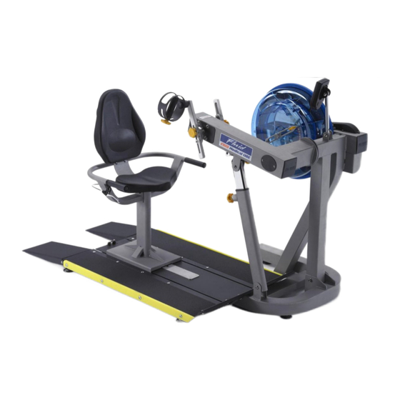
- Page 1 Owners Manual Wheelchair Accessible...
- Page 2 CAUTION As with any piece of fitness equipment, consult a physician be- fore beginning your E920 exercise program. WARNING Do not remove hands while crank is in motion. The crank will continue to rotate and could cause injury.
-
Page 3: Table Of Contents
Contents Box Contents Assembly Instructions Baseplate Addendum Seat Assemby Attaching Armrest Lower frame Attaching Armrest cable to Cable Pivot Install Seat Back and Seat Install Seat onto Baseplate Control Arm Slider Arm Installation Instructions Using Slider Arm Tank Filling and Water Treatment Long Term Water Treatment and Basic Operation Rower Ergometer Using the First Degree Fitness USB Interface... -
Page 4: Box Contents
Box Contents... - Page 5 Item Qty Description Item Qty Description Main Frame with Telescoping 8 M8 Washer Tube and Internal Gas Assist Shock 1 Baseplate (Install P-7) 3 M10 Washer 1 Seat (Install P-9) 4 M8 Springs Washer 8 M6x20mm bolt 1 4mm Allen Key 4 M8x15mm bolt 1 6mm Allen Key 8 M8x20mm bolt...
-
Page 6: Assembly Instructions
Assembly Instructions 4x M8x15mm Bolts and 4x M8 Spring Washers 3x Foot Leveler Adjuster Knob Remove contents from box. Attach telescoping tube to the underside of the control arm using 4x M8x15mm bolts[5] and 4x M8 spring washers[16]. The control arm is heavy and will swing freely during this stage of assembly. CAUTION The adjuster knob is pre-tightened from the factory in the optimal position for assembly in relation to the control arm. -
Page 7: Baseplate Addendum
Baseplate Addendum CONTENTS: PVC Sidecovers Ramp Right T-Track Ramp Left Note hardware bolt pack is used for both Seat Assembly and Baseplate. Remove contents from box and make sure all parts are present. Contents will in- clude the T-track, left/right side ramps and bolt pack (note, this may also be located with Seat Assembly). - Page 8 Step 2: Attach Left and Right ramps to the T-track using 8x M8x45mm bolts M8x45mm bolts Step 3: Once the Left and Right ramps have been installed to the sides of the T- track, secure the front end of each ramp as shown using 4x M8x25 bolt[7], 4x M8 Nylock nut[11] and 4x M8 washer [14].
-
Page 9: Seat Assemby
Seat Assembly Seat Main Frame Armrest Assembly Bolt Pack Seat back Seat CONTENTS: 1x Seat Main Frame 1x Lower Seat 1x Armrest Assembly 1x Upper Seat back 1x Bolt Pack (Note Bolts/Washers/Nuts are for both Seat and Footplate) You will need the Lower Frame, Armrest Assembly and the following bolts/ washers/nuts from the bolt Pack: 1x M8x70mm Bolt 3x M8 Nylock Nut... -
Page 10: Attaching Armrest Lower Frame
Attaching Armrest to Lower frame Mount the Armrest onto the Lower frame from behind as shown. Important! Before securing bolts (see following page), thread the plastic tie at- tached to the armrest cable through the hole as shown right. Plastic tie Secure Armrest with M8x70mm Bolt[9], M8 Nylock Nut[11] and M8 Washer[14] as shown... - Page 11 M8x25mm Bolt[7] and M8 Washer[14] 2x M8x45mm Bolt[8],2x M8 Nylock Nut [11] and 2x M8 Washer[14]...
-
Page 12: Attaching Armrest Cable To Cable Pivot
Attaching Armrest cable to Cable Pivot Locate plastic tie, then depress Cable Pivot forward to allow plastic tie to be pulled through the hole in front. Once the cable end is through the hole, slide it forward as shown upper right to prevent cable end from slipping back through. -
Page 13: Install Seat Back And Seat
Install Seat Back and Seat Seat Frame, Seat Back and Seat, 8x M6x20mm Bolt[4] and 8x M6 Washer [13] Install Seat Using 4x M6x20mm Bolt[4]/ Washer[13]. Install Seat Back with as shown with 4x M6x20mm Bolt[4]/Washer[13] Seat Once seat pads are installed the assem- bly will be complete. -
Page 14: Install Seat Onto Baseplate
Install Seat onto Baseplate Seat Stop: Must be lowered to allow seat onto Baseplate track. Must ALWAYS be in the LOCKED position when seat is occupied on Baseplate. Must be lowered to allow seat removal. To LOCK, raise and locate. To Seat Installation: Tilt the seat slightly upward to allow the front rollers to en- gage the channel. -
Page 15: Control Arm
Control Arm Chain tensioning bolts: Allows for tightening the chain or adjustment from side to side. Make sure when tightening only to adjust the same amount for both bolts, otherwise the sprocket will be misaligned. Note: Tightening the right bolt only (turning clockwise) will pull the right side of the crank assembly toward you, tightening the left will pull the left side toward you. -
Page 16: Slider Arm Installation Instructions
Slider Arm Kit Installation Instructions Slider Arm Kit includes 1x Slider Arm Assembly Right (includes right handle), 1x Slider Arm Assembly Left (includes left handle), 2x Yellow Adjustment Knobs with Nylon Spacers and 1x 3mm Allen key. Note: Slider Arms are marked ‘L’ and ‘R’. Improper installation will result in uneven Slider Arm adjustment. - Page 17 Step 1: Mount the left Slider Arm onto the axle using the yellow indicator hole to align the slider and axle. Step 2: Tighten the set screw onto the axle and into the yellow indicator hole using the 3mm Allen key. Step 3: Thread Adjustment Knob onto axle to secure the assembly.
- Page 18 Step 4: Repeat steps 1-3 to install right Slider Arm onto axle. The E920 Slider Arm Kit offers the user an entire range of added resistance set- tings and the ability to perform addition- al upper body workouts. To adjust, simply loosen the Adjustment Knobs, move Slider Arm to desired length and secure.
-
Page 19: Using Slider Arm
Using Slider Arm Additional Exercises: Training can now be achieved with both left and right Handgrips moving parallel , rather than in an opposed motion. Step 1: On the right Slider Arm Assem- bly, remove the adjustment knob, loosen set screw and remove Assembly from axle. -
Page 20: Tank Filling And Water Treatment
Tank Filling and Water Treatment Note: A large bucket is required for filling (Not included). In areas where tap water quality is known to be poor, FDF recommends the use of distilled water. Open the tank plug and insert hose into tank (rotating the impeller slightly may be necessary to allow the hose to pass), move the tank adjuster handle to level 20 and begin filling. -
Page 21: Long Term Water Treatment And Basic Operation
Long term water treatment: Water treatment schedules for the E820 will vary according to the fluid tanks exposure to sunlight but expect 8-12 months near a bright, sunlit window and 2-4 years for a darker location. At the point of finding the water slightly green, add a Chlorine tablet. -
Page 22: Rower Ergometer
You can choose to change UNITS displayed UNITS: Displays WATTS, SPM, HR, 500/m LEVEL: Adjustable from 1-20. Match LEVEL number with resistance level on the Fluid tank. SET: Changes Time, Distance parameters PROGRAM: Clears current exercise program RESET: Clears data... -
Page 23: Using The First Degree Fitness Usb Interface
Using the First Degree Fitness USB Interface Description: The USB connectivity now built in to all new models of FDF Console and IPM allow you to enhance your exercise experience by connecting to your home PC or Laptop. Using FDF's own sample applications you can exercise while enjoying your favorite movies. -
Page 24: Maintenance Chart
Maintenance Chart Item Timeframe Instructions Notes Seat and Weekly. Wipe down weekly with lint Frame. free cloth or more often with heavy club use. PK belt tension. Monthly. Check monthly for signs of slippage. Refer to “Tank belt adjustment” page. Tank and water 12 months to 4 Follow instructions as speci-... -
Page 25: Troubleshooting
Troubleshooting Probable Fault Solution Cause Tank internal surfaces Rower is in direct Add water treatment or change tank wa- show green deposit. sunlight or has not ter as directed in the water treatment sec- had water treat- Consider using dis- tion of this manual. -
Page 26: Tank Belt Adjustment
Tank Belt Adjustment Remove large metal inspection plate as shown above right. Using a long tool, push out the rear end cap as pictured right. This will give you access to the tank tensioning bolt (shown bottom right). End Cap Loosen both the front and rear tank bolts as shown below. -
Page 27: Warranty
This product is designed and constructed for use in any Health Club / Fitness Studio application First Degree Fitness Limited warrants that the Fluid Upper Body Ergometer (model UB-E920), purchased from an authorised agent and in its undamaged original packaging, is free from defects in materials and workmanship. First Degree Fitness Limited or its agent will, at their discretion, repair or replace parts that become defective within the warranty period, subject to the specific inclusions and exclusions below.
Need help?
Do you have a question about the UBE920 and is the answer not in the manual?
Questions and answers