Table of Contents
Advertisement
Quick Links
Advertisement
Table of Contents

Subscribe to Our Youtube Channel
Related Manuals for IFM Electronic efector300 SI5010


Summary of Contents for IFM Electronic efector300 SI5010
- Page 1 Operating instructions Flow monitor SI5010...
-
Page 2: Table Of Contents
Contents 1 Preliminary note ���������������������������������������������������������������������������������������������������3 1�1 Explanation of symbols ����������������������������������������������������������������������������������3 2 Safety instructions �����������������������������������������������������������������������������������������������3 3 Functions and features ����������������������������������������������������������������������������������������4 3�1 Applications ��������������������������������������������������������������������������������������������������4 3�2 Operating principle flow monitoring ���������������������������������������������������������������4 4 Installation������������������������������������������������������������������������������������������������������������5 4�1 Installation location ����������������������������������������������������������������������������������������5 4�2 Interference in the pipe system ���������������������������������������������������������������������6 4�3 Installation procedure ������������������������������������������������������������������������������������6 5 Electrical connection ��������������������������������������������������������������������������������������������7 6 Operating and display elements ��������������������������������������������������������������������������8... -
Page 3: Preliminary Note
11 Technical data ��������������������������������������������������������������������������������������������������14 1 Preliminary note 1.1 Explanation of symbols ► Instructions > Reaction, result → Cross-reference Important note Non-compliance can result in malfunction or interference� Information Supplementary note� LED lights green LED lights orange LED lights red LED flashes 2 Safety instructions • Please read this document prior to set-up of the unit�... -
Page 4: Functions And Features
liability for consequences of misuse by the operator� Improper installation and use of the devices result in a loss of the warranty claims� 3 Functions and features 3.1 Applications The unit monitors the flow in liquid and gaseous media� 3.2 Operating principle flow monitoring • The unit detects the flow speed to the calorimetric measuring principle and switches the output: - output closed if medium is flowing / output open if no medium is flowing�... -
Page 5: Installation
4 Installation Using process adapters the unit can be adapted to different process connections� • Adapters have to be ordered separately as accessories� A correct fit of the unit and ingress resistance of the connection are only en- sured using ifm adapters� • For small flow rates ifm adapter blocks are available�... -
Page 6: 4�2 Interference In The Pipe System
4.2 Interference in the pipe system Components integrated in the pipes, bends, valves, reductions, etc� lead to turbu- lence of the medium� This affects the function of the unit� Recommendation: Adhere to the distances between sensor and sources of inter- ference: 5...10 x D 3...5 x D... -
Page 7: Electrical Connection
5 Electrical connection The unit must be connected by a qualified electrician� The national and international regulations for the installation of electrical equipment must be adhered to� Voltage supply according to EN 50178, SELV, PELV� ► Disconnect power� ► Connect the unit as follows: Pin 1 Pin 2 • Programming wire for remote setting... -
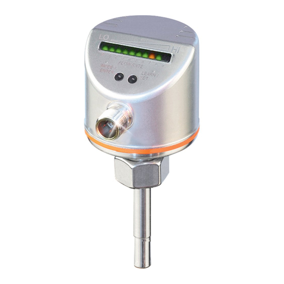
Page 8: Operating And Display Elements
6 Operating and display elements Flow High 0 1 2 3 4 5 6 7 8 9 Setpoint 1: Operation indication • The green LEDs indicate the current flow (LEDs 0 to 9 represent the range between flow standstill and maximum flow)� • A lighting LED indicates the position of the switch point (orange = output closed, red = output open)�... -
Page 9: 7�1�2 Device-Specific Information
7.1.2 Device-specific information You will find the IODDs necessary for the configuration of the IO-Link unit and detailed information about process data structure, diagnostic information and parameter addresses at www�ifm�com/gb/io-link� 7.1.3 Parameter setting tools You will find all necessary information about the required IO-Link hardware and software at www�ifm�com/gb/io-link�... -
Page 10: 7�2 Set-Up And Settings For Water
7.2 Set-up and settings for water For media other than water → 7.5 Low-flow adjustment (optional). ► Switch on the supply voltage� > All LEDs light and go out again step by step� During this time the output is closed (if configured as normally open)� The unit is in the operating mode� ►... -
Page 11: 7�4 High-Flow Adjustment (Optional)
7.4 High-flow adjustment (optional) ► Let the normal flow circulate in the installation� ► Press and keep it pressed� > LED 9 lights, after approx� 5 s it flashes� ► Release the button� The unit is now adapted to your flow conditions� It returns to the operating mode, the display should now show example 1�... -
Page 12: 7�7 Restore The Factory Setting (Reset)
7.7 Restore the factory setting (reset) ► Press for at least 15 s� > LED 9 lights, after approx� 5 s it flashes� > After approx� 15 s LEDs 0���9 flash orange� ► Release the button� All settings are reset to the factory setting: - operating range: 5 ���100 cm/s for water - switch point: LED 7 - output function: NO... -
Page 13: 8�1 Operating Indicators
8.1 Operating indicators Green LED bar: current flow within the display range� Indication of the switch point (SP): 0 1 2 3 4 5 6 7 8 9 - LED orange: output closed� - LED red: output open� LED 9 flashes: current flow above the display range�... -
Page 14: Maintenance
Possible causes Corrective measures ► Read chapter → 4 Installation. Check Error during installation� whether all requirements have been met� The difference between maximum flow and ► Increase the flow difference and carry minimum flow is too small� out the adjustment again� The sequence high-flow / low-flow adjust- ►...
Need help?
Do you have a question about the efector300 SI5010 and is the answer not in the manual?
Questions and answers