Table of Contents
Advertisement
Quick Links
Advertisement
Table of Contents

Subscribe to Our Youtube Channel
Related Manuals for IFM Electronic E30430


Summary of Contents for IFM Electronic E30430
- Page 1 Operating instructions IO-Link INLINE DISPLAY 1.44" E30430...
-
Page 2: Table Of Contents
Contents Safety instructions ....................2 2 Functions and features ..................3 3 Function .......................4 4 Installation ......................4 5 Electrical connection ....................4 6 Operating and display elements ................5 7 Set-up ........................6 7.1 Device catalogue update ................6 8 Menu ........................6 9 Parameter setting ....................8 9.1 Parameter setting in general .................8 10 Troubleshooting ....................8 Technical data, approvals, accessories and further information at... -
Page 3: Functions And Features
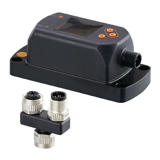
2 Functions and features The IO-Link INLINE DISPLAY is used for indicating process values and the corres- ponding information from a connected IO-Link sensor. The parameters of the connected sensor cannot be set via the INLINE DISPLAY. Example of a system integration 1: IO-Link sensor 2: IO-Link INLINE DISPLAY 3: IO-Link master... -
Page 4: Function
3 Function During operation, the device determines the process data that is cyclically trans- mitted by the sensor and indicates it on the display and as LED status. 4 Installation ► Insert the unit into the system so that no mechanical forces are exerted on the housing. -
Page 5: Operating And Display Elements
6 Operating and display elements 1, 2: Indicator LEDs • LED 1 = switching status OUT1 (is on when output 1 on the connected device is switched) • LED 2 = switching status OUT2 (is on when output 2 on the connected device is switched) 3: TFT display •... -
Page 6: Set-Up
7 Set-up The device can indicate process values of ifm units. No settings are necessary. In case the connected ifm unit cannot be displayed: ► Update the internal device catalogue (→ 7.1). 7.1 Device catalogue update ► Connect the INLINE DISPLAY with the computer using the USB IO-Link master E30390. - Page 7 Explanation of the main menu PDis Opening of the lower menu level PDis. Opening of the lower menu level EF. Explanation of the process value display (PDis) LED Switching status LEDs: ON, OFF PV.x Process value display: = process value is not displayed bk/wh = black or white, depending on the setting of the background ddiS.S = red green = green...
-
Page 8: Parameter Setting
9 Parameter setting 9.1 Parameter setting in general 1. Change from the RUN mode to the main menu [●] 2. Select the requested parameter [▲] or [▼] 3. Change to the setting mode [●] 4. Modification of the parameter value [▲] or [▼] >... - Page 9 Display Description Type Instructions No IO-Link Error • If the device is only connected connection connection between to a power supply, this status is the master and the normal. device was found • If parameter IO-Link = OFF: ► Check the cable connections and the function of the connec- ted IO-Link participants ►...
-
Page 10: Display Description
Display Description Type Instructions The setting buttons Warning ► Unlock the unit → 6 Operating on the unit are and display elements. locked, Parameter change rejected. C.Loc Parameter setting Warning ► Wait until the parameter setting via pushbuttons via the remote participant is disabled, finished.
Need help?
Do you have a question about the E30430 and is the answer not in the manual?
Questions and answers