Table of Contents
Advertisement
Quick Links
Advertisement
Table of Contents

Related Manuals for IFM Electronic E2M231


Summary of Contents for IFM Electronic E2M231
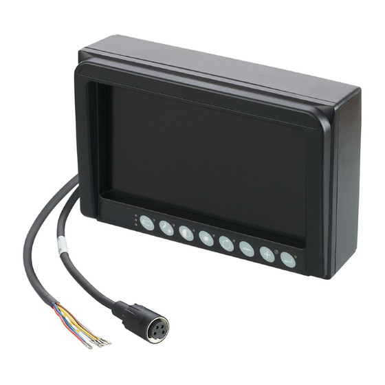
- Page 1 Installation instructions Monitor for analogue cameras E2M231 E2M232...
-
Page 2: Table Of Contents
Contents 1 Preliminary note �������������������������������������������������������������������������������������4 1�1 Symbols used ����������������������������������������������������������������������������������4 1�2 Warnings used ���������������������������������������������������������������������������������4 2 Safety instructions ���������������������������������������������������������������������������������5 3 Functions and features ��������������������������������������������������������������������������5 4 Items supplied����������������������������������������������������������������������������������������6 5 Installation����������������������������������������������������������������������������������������������7 5�1 Mounting accessories ����������������������������������������������������������������������7 5�2 Locator for mounting accessories ���������������������������������������������������� 8 5�3 Rotate cable connection ������������������������������������������������������������������9 6 Electrical connection ����������������������������������������������������������������������������... - Page 3 7�1 Cleaning ��������������������������������������������������������������������������������������� 18 7�2 Repair �������������������������������������������������������������������������������������������� 18 7�3 Disposal ����������������������������������������������������������������������������������������� 18 8 Approvals/standards ���������������������������������������������������������������������������� 19 Licences and trademarks All trademarks and company names used are subject to the copyright of the respective companies�...
-
Page 4: Preliminary Note
1 Preliminary note This document is intended for specialists� These specialists are people who are qualified by their appropriate training and their experience to see risks and to avoid possible hazards that may be caused during operation or maintenance of the device� The document contains information about the correct handling of the device�... -
Page 5: Safety Instructions
The device is available in 2 versions: • with 1 analogue video input (E2M231) • with 2 analogue video inputs (E2M232) The following cameras from ifm electronic are compatible with the device: • O2M2xx • O3M2xx Because of the requirements for electromagnetic interference emissions, the device is intended for use in industrial environments�... -
Page 6: Items Supplied
► Do not touch the screen� 4 Items supplied • E2M23x monitor • Connection cable for power supply • Only E2M231: connection cable for 1 analogue video input and controller • Only E2M232: connection cable for 2 analogue video inputs and controller •... -
Page 7: Installation
5 Installation 5.1 Mounting accessories The device is supplied without mounting accessories� The hole dimensions of the device are not compatible with the standard RAM mounting plate� Install the device using one of the ® following accessories: • E2M236 - mounting arm monitor 90 mm •... -
Page 8: 5�2 Locator For Mounting Accessories
5.2 Locator for mounting accessories The back of the device has been prepared for fixing the mounting accessories� The 11 M5 tapped holes have a thread length of 8 mm� 40,5 Locator for mounting accessories (back of the unit) Screw the mounting accessories to the device applying 2 Nm�... -
Page 9: 5�3 Rotate Cable Connection
5.3 Rotate cable connection The cable connection of the device can be rotated by 180 degrees� This allows that the cables from the device can be laid from the top or the bottom� NOTE The protection rating indicated in the data sheet is ensured if the device continues to be ingress-resistant after the cable connection has been rotated�... - Page 10 6� Place the cable connection on the device rotated by 180 degrees (6)� 7� Tighten the cable connection with socket head screws applying 0�35 Nm (7)� 8� Verify correct and tight position of the cable connection� 9� Insert the rubber stopper into the cable connection (8)�...
-
Page 11: Electrical Connection
Information about the available accessories: 6.2 Wiring (1) Power supply 7 cables, open ends U+ (18���30 V DC) white blue Activate camera 1 brown Activate camera 2 white/ Activate camera 3 yellow Activate camera 4/ E2M231 grey tachometer yellow Parking brake... -
Page 12: 6�3 Connection And Laying Of Cables
(2) Analogue video input M16 socket, 4 poles Coax cable core (video signal) Coax screen (video GND) U+ (12 V DC) E2M232 6.3 Connection and laying of cables www�ifm�com ► Use screened cables from ifm: E2M203: M16 connection cable, gold-plated contacts, 5 m long E2M204: M16 connection cable, gold-plated contacts, 11 m long E2M205: M16 connection cable, gold-plated contacts, 16 m long E2M206: M16 connection cable, gold-plated contacts, 21 m long... -
Page 13: 6�4�1 Vehicles With Separate Ground
Protect the supply voltage (max� 5 A) to protect the device� 6.4.1 Vehicles with separate ground For vehicles with separate power wiring (e�g� fork lift trucks) connect the operating voltage as follows: ► Connect the red wire (U+) of the operating voltage cable (→... -
Page 14: 6�5 Analogue Video Inputs
The analogue video inputs are not short-circuit proof� Observe the bending radius of the cable of >= 50 mm� Cover unused connectors with protective caps� The following cameras from ifm electronic are compatible with the device: • O2M2xx • O3M2xx... -
Page 15: 6�7 Set Up The Camera Monitor System
If several voltages are applied simultaneously, the camera with the highest number takes priority and its images are displayed� Example: 7���30 V DC are applied to cameras 1 and 2� The image from camera 2 is displayed� A camera image is no longer displayed if the voltage drops to "<... -
Page 16: 6�8 Application Examples
6.8 Application examples 6.8.1 Connect device with 1 camera Connection of 1 O2M200 analogue camera with an E2M231 monitor 1� E3M231 monitor 2� E2M203 connection cable, 5 m 3� O2M200 analogue camera 6.8.2 Connect device with 2 cameras Connection of 2 O2M200 analogue cameras with an E2M231 monitor 1�... -
Page 17: 6�8�3 Connect Device With 3 Cameras
6.8.3 Connect device with 3 cameras Connection of 3 O2M200 analogue cameras with an E2M231 monitor 1� E3M231 monitor 2� E2M235 video switcher, 3 ports 3� E2M203 connection cable, 5 m 4� O2M200 analogue camera 6.8.4 Connect device with 4 cameras Connection of 4 O2M200 analogue cameras with an E2M232 monitor 1�... -
Page 18: Maintenance, Repair And Disposal
7 Maintenance, repair and disposal 7.1 Cleaning Unsuitable cleaning agents and chemicals can damage the display surface� The following agents are not suited for cleaning the display: • chemicals dissolving plastics such as methylated spirit, benzine, thinner, alcohol, acetone or ammonia •... -
Page 19: Approvals/Standards
8 Approvals/standards The CE declaration of conformity and approvals can be found at: www�ifm�com...
Need help?
Do you have a question about the E2M231 and is the answer not in the manual?
Questions and answers