Table of Contents
Advertisement
Quick Links
INSTALLATION AND MAINTENANCE INSTRUCTIONS
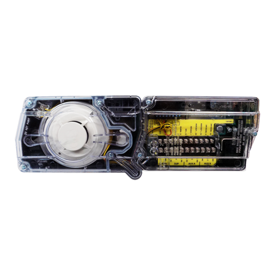
D4120 Duct Smoke Detectors
D4S Sensor Component
JD4P120 Power Board Component
NOTE: The D4120 duct detector consists of JD4P120 Power Board component and the D4S Sensor component.
SPECIFICATIONS
Operating Temperature:
Storage Temperature:
Humidity:
Air Velocity:
D4120 Footprint
Dimensions:
D4S/JD4P120 Footprint Dimensions:
D4120 Weight:
Electrical
Power supply voltage:
Input capacitance:
Reset Voltage:
Reset Time (with RTS451/RTS151):
Reset Time (by power down):
Power Up Time:
Alarm response time:
Sensitivity Test:
Current Requirements (Using No Accessories)
Max. standby current
Max. alarm current
CONTACT RATINGS
Alarm initiation contacts (SPST)
Alarm auxiliary contatcs (DPDT)
NOTE: Alarm auxiliary contacts shall not be connected to initiating circuits of
control panels. Use the alarm initiation contact for this purpose.
Supervisory Contacts (SPDT)
TABLE OF CONTENTS
[1] Limitations of Duct Smoke Detectors. . . . . . . . . . . . . . . . . . . . . . . . . . 1
[2] Exploded View of Duct Smoke Detector Components . . . . . . . . . . . . . 2
[3] General Description . . . . . . . . . . . . . . . . . . . . . . . . . . . . . . . . . . . . . . 2
[4] Contents of Duct Smoke Detector Kit. . . . . . . . . . . . . . . . . . . . . . . . . . 2
[5] Detector Installation . . . . . . . . . . . . . . . . . . . . . . . . . . . . . . . . . . . . . . 2
[6] Sampling Tube Installation . . . . . . . . . . . . . . . . . . . . . . . . . . . . . . . . . 3
[7] Measurement Tests . . . . . . . . . . . . . . . . . . . . . . . . . . . . . . . . . . . . . . . 3
[8] Field Wiring Installation Guidelines. . . . . . . . . . . . . . . . . . . . . . . . . . . 4
[9] Unit Configuration . . . . . . . . . . . . . . . . . . . . . . . . . . . . . . . . . . . . . . . 5
[10] Detector Status Indication . . . . . . . . . . . . . . . . . . . . . . . . . . . . . . . . . 6
[11] Interconnection (Multiple Fan Shut Down). . . . . . . . . . . . . . . . . . . . . 6
[12] Verification of Operation . . . . . . . . . . . . . . . . . . . . . . . . . . . . . . . . . . 6
[13] Detector Cleaning Procedures . . . . . . . . . . . . . . . . . . . . . . . . . . . . . . 7
[14] Sensor replacement. . . . . . . . . . . . . . . . . . . . . . . . . . . . . . . . . . . . . . 7
[15] Optional Accessories. . . . . . . . . . . . . . . . . . . . . . . . . . . . . . . . . . . . . 7
Wiring Diagrams . . . . . . . . . . . . . . . . . . . . . . . . . . . . . . . . . . . . . . . . . . 5-7
Warranty . . . . . . . . . . . . . . . . . . . . . . . . . . . . . . . . . . . . . . . . . . . . . . . . 8
BEFORE INSTALLING
Read System Sensor's Applications Guide for Duct Smoke Detectors (HVAG53),
which provides information on detector spacing, placement, zoning, wiring,
and special applications. This manual is available online at www.systemsen-
sor.com. NFPA Standards 72 and 90A should also be referenced for detailed
information.
NOTICE: This manual shall be left with the owner/user of this equipment.
D4120 & D4S: -4° to 158° F (-20° to 70° C) JD4P120: -40° to 158° F (-40° to 70° C)
D4120 & D4S: -22° to 158° F (-30° to 70° C) JD4P120: -40° to 158° F (-40° to 70° C)
0% to 95% Relative Humidity Non-condensing
100 to 4000 ft./min. (0.5 to 20.3 m/sec.)
Rectangular - 14.38 in L x 5 in W x 2.5 in D (37cm L x 12.7cm W x 6.36cm D)
Square - 7.75 in L x 9 in W x 2.5 in D (19.7cm L x 22.9cm W x 6.35cm D)
7.75 in L x 5 in W x 2.5 in D (19.7cm L x 12.7cm W x 6.35cm D)
2.5 pounds; 1.14 kg
20-29 VDC
270 µF max.
3.0 VDC min.
.03 to 0.3 sec.
0.6 sec. max.
35 sec. max.
15 sec.
See detector label
21 mA @ 24 VDC
65 mA @ 24 VDC
2.0A @ 30 VDC (resistive)
10A @30 VDC (resistive)
10A @250 VAC (resistive)
1
/
HP @240 VAC
2
1
/
HP @120 VAC
4
2.0A @ 30 VDC (resistive)
2.0A @ 125 VAC (resistive)
24 VAC 50-60-Hz
270 µF max.
2.0 VAC min.
.03 to 0.3 sec.
0.6 sec. max.
35 sec. max.
15 sec.
See detector label
65 mA RMS @ 24VAC 60Hz
135 mA RMS @ 24 VAC 60 Hz
ACCESSORY CURRENT LOADS AT 24 VDC
DEVICE
APA151/APA451
MHR/MHW
RA400Z/RA100Z
RTS451/RTS151
RTS451KEY/RTS151KEY
RTS2
RTS2-AOS
NOTE: Any combination of accessories may be used such that the given accessory
loads are: 110mA or less at the Aux output, and 50mA or less at the Alarm output.
IMPORTANT: This detector must be tested and maintained regularly following
PAGE
NFPA 72 requirements. The detector must be tested an maintained regularly fol-
lowing NFPA 72 requirements. According to NFPA, the detector should be visu-
ally inspected semiannually and functionally tested at least once a year. This
may need to be more frequent depending on the air quality of the duct supply air.
[1] LIMITATIONS OF DUCT SMOKE DETECTORS
The National Fire Protection Association has established that DUCT DETEC-
TORS MUST NOT BE USED AS A SUBSTITUTE FOR OPEN AREA DETECTOR
PROTECTION as a means of providing life safety. Nor are they a substitute for
early warning in a building's regular fire detection system.
System Sensor supports this position and strongly recommends that the user
read NFPA Standards 90A, 72, and 101. The D4120 Air Duct Smoke Detectors
are listed per UL 268A.
This device will not operate without electrical power. Fire situations may
cause an interruption of power. The system safeguards should be discussed
with your local fire protection specialist.
This device will not sense smoke unless the ventilation system is operating
and the cover is installed.
For this detector to function properly, it MUST be installed according to the in-
structions in this manual. Furthermore, the detector MUST be operated within
ALL electrical and environmental specifications listed in this manual. Failure
to comply with these requirements may prevent the detector from activating
when smoke is present in the air duct.
1
3825 Ohio Avenue, St. Charles, Illinois 60174
1-800-SENSOR2, FAX: 630-377-6495
www.systemsensor.com
120 VAC 50-60 Hz
N/A
10 VAC min.
.03 to 0.3 sec.
0.6 sec. max.
35 sec. max.
15 sec.
See detector label
20 mA RMS @ 120 VAC 60 Hz
35 mA RMS @ 120 VAC 60 Hz
STANDBY
TROUBLE
12.5mA
n/a
0mA
n/a
0mA
n/a
0mA
n/a
12mA
n/a
3mA Max.
16mA Max.
3mA
16mA Max.
WARNING
ALARM
30mA Max.
29mA Max.
12mA Max.
12mA Max.
12mA Max.
30mA Max.
55mA Max.
I56-5841-001R
06-10
Advertisement
Table of Contents

Related Manuals for System Sensor INNOVAIR FLEX JD4P120


Summary of Contents for System Sensor INNOVAIR FLEX JD4P120
- Page 1 [11] Interconnection (Multiple Fan Shut Down)..... 6 System Sensor supports this position and strongly recommends that the user [12] Verification of Operation ........6 read NFPA Standards 90A, 72, and 101.
- Page 2 [2] FIGURE 1. EXPLODED VIEW OF DUCT SMOKE DETECTOR COMPONENTS: EXHAUST TUBE 4-WIRE POWER BOARD POWER BOARD MODULE COVER SENSOR MODULE COVER METAL SAMPLING TUBE (sold seperately) SENSOR HEAD MAGNET TEST LOCATION H0549-06 [3] GENERAL DESCRIPTION [5.2] DETERMINE MOUNTING LOCATION AND CONFIGURATION Smoke introduced into an air duct system will be distributed throughout the On ducts wider than 18 inches it is recommended that the detector be entire building.
- Page 3 [5.3.2] FOR SQUARE TOP-OVER-BOTTOM MOUNTING CONFIGURATION ported at the end opposite the duct detector. In ducts wider than 8 feet, OR D4S SENSOR COMPONENT MOUNTING: work must be performed inside the duct to couple the other section of Center punch at (4) target centers: (2) “A” for sampling tubes and (2) “C” for the sampling tube to the section already installed using the inch con- the square configuration mounting tabs as shown on mounting template.
- Page 4 [7.2] LOW FLOW AIR FLOW TEST USING DWYER SERIES 607 [8] FIELD WIRING INSTALLATION GUIDELINES DIFFERENTIAL PRESSURE TRANSMITTER All wiring must be installed in compliance with the National Electrical Code Verify the air speed of the duct using an anemometer. Air speed must be at and the local codes having jurisdiction.
- Page 5 FIGURE 7. SYSTEM WIRING DIAGRAM FOR 4-WIRE DUCT SMOKE DETECTORS: CAUTION Do not loop wire under terminals when wiring detectors. Break wire runs to provide system supervision of connections. POWER INPUTS (NOTE 1) POWER INPUTS (NOTE 1) 24VAC/DC AUXILIARY CONTACTS AUXILIARY CONTACTS FOR FAN SHUTDOWN, ETC.
- Page 6 [10] DETECTOR STATUS INDICATION seconds and power board will blink amber as depicted in Table 3 on page 8. Detector Staus is indicated by the LED sensor, and the correcsponding LED on The maintenance condition indicates that the sensor is operating outside its the power board.
- Page 7 [13] DETECTOR CLEANING PROCEDURES [15.2] RTS2/RTS2-AOS MULTI-SIGNALING ACCESSORY Notify the proper authorities that the smoke detector system is undergoing The RTS2 and RTS2-AOS multi-signaling accessories are designed for use with maintenance, and that the system will temporarily be out of service. Disable InnovairFlex 4-wire conventional duct smoke detectors only.
- Page 8 Aux Relay does not switch states: Terminals 6 and 16 are closed, Terminals 8 and 18 are closed NOTE: If any other visual indication is noted contact System Sensor technical support at 1-800-SENSOR2. Please refer to insert for the Limitations of Fire Alarm Systems...
Need help?
Do you have a question about the INNOVAIR FLEX JD4P120 and is the answer not in the manual?
Questions and answers