Table of Contents
Advertisement
Quick Links
Advertisement
Table of Contents

Related Manuals for TQ TQMa6ULxL


Summary of Contents for TQ TQMa6ULxL
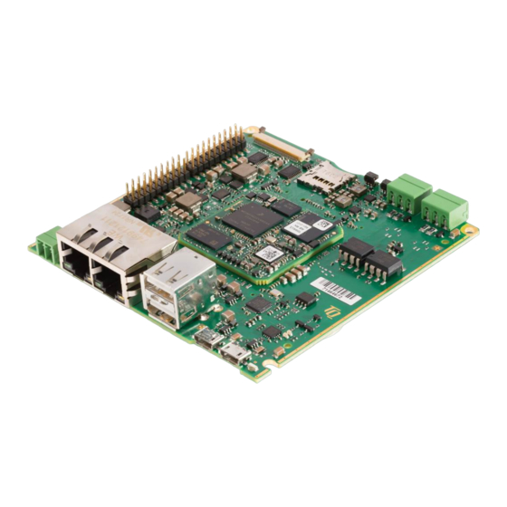
- Page 1 MBa6ULxL User's Manual MBa6ULxL UM 0102 10.01.2022...
-
Page 2: Table Of Contents
User's Manual l MBa6ULxL UM 0102 l © 2022, TQ-Systems GmbH Page i TABLE OF CONTENTS ABOUT THIS MANUAL ....................................1 Copyright and license expenses ................................1 Registered trademarks ....................................1 Disclaimer ........................................1 Imprint ..........................................1 Tips on safety ........................................ 2 Symbols and typographic conventions ............................... - Page 3 User's Manual l MBa6ULxL UM 0102 l © 2022, TQ-Systems GmbH Page ii Packaging ........................................28 Batteries ........................................28 8.6.1 General notes ......................................28 8.6.2 Lithium batteries ...................................... 28 Other entries ......................................28 APPENDIX ........................................29 Acronyms and definitions..................................29...
- Page 4 User's Manual l MBa6ULxL UM 0102 l © 2022, TQ-Systems GmbH Page iii TABLE DIRECTORY Table 1: Terms and Conventions .................................... 2 Table 2: Overview interfaces ....................................4 Table 3: Boot-Mode configuration ..................................7 Table 4: Boot-Mode configuration DIP switches – S13, S16 ........................... 7 Table 5: I2C4 address assignment ..................................
- Page 5 User's Manual l MBa6ULxL UM 0102 l © 2022, TQ-Systems GmbH Page iv FIGURE DIRECTORY Figure 1: Block diagram MBa6ULxL ..................................4 Figure 2: Block diagram TQMa6ULxL ..................................5 Figure 3: Block diagram Boot Mode ..................................6 Figure 4: Position of Boot-Mode configuration DIP switches – S13, S16 ..................... 7...
-
Page 6: About This Manual
User's Manual, or due to usage of erroneous or incomplete information, are exempted, as long as there is no proven intentional or negligent fault of TQ-Systems GmbH. TQ-Systems GmbH explicitly reserves the rights to change or add to the contents of this User's Manual or parts of it without special notification. -
Page 7: Tips On Safety
User's Manual l MBa6ULxL UM 0102 l © 2022, TQ-Systems GmbH Page 2 Tips on safety Improper or incorrect handling of the MBa6ULxL can substantially reduce its life span. Symbols and typographic conventions Table 1: Terms and Conventions Symbol Meaning This symbol represents the handling of electrostatic-sensitive modules and / or components. -
Page 8: Naming Of Signals
This User's Manual describes the hardware of the MBa6ULxL, revision 02xx. The MBa6ULxL is designed as a carrier board for the LGA version of the TQMa6ULxL. The figures in this User's Manual also refer to the TQMa6ULxL. In addition the standard interfaces routed to the user’s connectors, more interfaces like CAN, UART, RS-232, GPIO, I C and SPI interfaces are routed to headers on the MBa6ULxL. -
Page 9: System Architecture And Functionality
Functionality Core of the MBa6ULxL is the TQMa6ULxL, which is based on an NXP i.MX6ULx CPU. In addition to the standard communication interfaces like USB, Ethernet, RS-232, etc. other signals and interfaces are routed to two 20-pin 2.54 mm headers. -
Page 10: Electronics
The TQMa6ULxL with the i.MX6ULx CPU is the central system component. It provides DDR3L SDRAM, eMMC, NOR flash and EEPROM memory. All voltages required by the TQMa6ULxL are derived from the supply voltage. More information is to be taken from the accompanying User’s Manual of the TQMa6ULxL (7). -
Page 11: Boot-Mode Configuration
User's Manual l MBa6ULxL UM 0102 l © 2022, TQ-Systems GmbH Page 6 3.1.2 Boot-Mode configuration The TQMa6ULxL can boot from different media: • eMMC (on TQMa6ULxL) • QSPI NOR flash • SD card The settings of DIP switches S13 and S16 determine, which device is selected to boot from. - Page 12 3.1.2 Boot-Mode configuration (continued) The following tables describe the DIP switch settings for each boot source. Further settings such as transfer modes and CPU clock are to be taken from the TQMa6ULxL User's Manual (7). Table 3: Boot-Mode configuration Boot-Mode...
-
Page 13: I 2 C Address Mapping
C touch screen controller can be addressed via I2C4 on the MBa6ULxL. Table 5 shows the addresses used on the TQMa6ULxL and the MBa6ULxL. The I2C4 bus is also routed to header X22. The following table shows the address assignment of TQMa6ULxL and MBa6ULxL. -
Page 14: Port Replicator Pca9554Bs Signals
MBa6ULxL! 3.1.5 Temperature sensor / SPD EEPROM Since there is already a temperature sensor SE97BTP on the TQMa6ULxL, no temperature sensor is provided on the MBa6ULxL. 3.1.6 RTC supply The TQMa6ULxL provides a discrete RTC. Another RTC is provided by the i.MX6ULx on the TQMa6ULxL. -
Page 15: Reset And Power
User's Manual l MBa6ULxL UM 0102 l © 2022, TQ-Systems GmbH Page 10 3.1.7 Reset and Power The MBa6ULxL provides a power and a reset button. Signal RESET_OUT# resets all components on the MBa6ULxL. The following table shows the signals. -
Page 16: Communication Interfaces
Common Mode Choke in series The USB host port of the TQMa6ULxL provides a theoretical data rate of 480 Mbit/s. The data rate is shared amongst the connected ports. The data rates of the ports can significantly deviate depending on the hardware and software used. -
Page 17: Usb 2.0 Hi-Speed Otg
The interface can serve as Client or Host. To use this feature, appropriate software support is necessary, however. The OTG ports of the TQMa6ULxL provide a theoretical data rate of 480 Mbit/s. The data rate can significantly deviate depending on the hardware and software used. -
Page 18: Ethernet
User's Manual l MBa6ULxL UM 0102 l © 2022, TQ-Systems GmbH Page 13 3.2.3 Ethernet Both i.MX6ULx MACs are provided on the MBa6ULxL via two SMSC PHYs LAN8720Ai. The PHYs are connected via RMII. The implementation is shown in the following block diagram. -
Page 19: Can
User's Manual l MBa6ULxL UM 0102 l © 2022, TQ-Systems GmbH Page 14 3.2.4 The MBa6ULxL provides two CAN interfaces. CAN1 is routed to X1, CAN2 is optionally available at X2. Both interfaces are galvanically separated. The CAN interfaces are not separated galvanically among themselves. -
Page 20: Touch Controller
The i.MX6ULx Touch Screen Controller (TSC) signals are used for USB OTG. Therefore a separate TSC STMPE811 is assembled on the MBa6ULxL. The STMPE811 is connected to I2C4 using address 0x41. 3.2.7 Backlight control Attention, TBD: The display brightness can be controlled at pin X19-5 with PWM signal PWM4 (TQMa6ULxL, pad H15). -
Page 21: Micro Sd Card Connector
Micro SD card connector The Micro SD card connector is connected to the USDHC1 controller on the TQMa6ULxL with a 4-bit wide data interface. 3.3 V are provided at the Micro SD card connector. All data lines provide ESD protection. -
Page 22: Mini Pcie And Sim Card Socket
User's Manual l MBa6ULxL UM 0102 l © 2022, TQ-Systems GmbH Page 17 3.2.9 Mini PCIe and SIM card socket Two Mini PCIe connectors for full-size Mini PCIe cards (50.95 × 30 mm) are provided on the MBa6ULxL. Every standard Mini PCIe card can be used . - Page 23 User's Manual l MBa6ULxL UM 0102 l © 2022, TQ-Systems GmbH Page 18 3.2.9 Mini PCIe and SIM card socket3.1.2 (continued) The following table shows the pinout of Mini PCIe connectors and SIM card socket. Table 21: Pinout Mini PCIe – X24, X25; SIM card socket – X12...
-
Page 24: Sim Card Socket
User's Manual l MBa6ULxL UM 0102 l © 2022, TQ-Systems GmbH Page 19 3.2.10 SIM card socket The following table shows the pinout of the SIM card socket. Table 22: Pinout SIM card socket – X12 Signal Remark SIM_PWR –... -
Page 25: 20-Pin Headers
User's Manual l MBa6ULxL UM 0102 l © 2022, TQ-Systems GmbH Page 20 3.2.11 20-pin headers The MBa6ULxL is equipped with two 20-pin headers with 2.54 mm pitch. 3.3 V, 5 V, SPI, I2C4, ADC UART 1 RS-232_1 RS232 Transceiver... -
Page 26: Diagnostic- And User Interfaces
Debug interfaces RS-232 / USB Debug interfaces are available as RS-232 and USB device interface on the MBa6ULxL. In both cases, the UART1 interface of the TQMa6ULxL is used. No software configuration is required. DIP switch S16-1 selects the debug interface, see Table 26. -
Page 27: Power Supply
User's Manual l MBa6ULxL UM 0102 l © 2022, TQ-Systems GmbH Page 22 Power supply The MBa6ULxL is supplied with 6.5 to 30 V via X21. All other voltages are generated on the MBa6ULxL. Additionally, 3.3 V and 5 V are available at headers X22 and X23. -
Page 28: Power Consumption
User's Manual l MBa6ULxL UM 0102 l © 2022, TQ-Systems GmbH Page 23 3.4.2 Power consumption The typical power consumption of the MBa6ULxL without display is approximately 3 ~ 4 watts. If however a display is powered by the MBa6ULxL, the power consumption depends on the display connected. -
Page 29: Software
User's Manual l MBa6ULxL UM 0102 l © 2022, TQ-Systems GmbH Page 24 SOFTWARE The following table provides an overview of the implemented software interfaces: Table 28: Software interfaces Device Function Supported Linux Resolutions: from 800 × 480 Colour depth: 24 bit, 24 bit RGB interface i.MX6UL... -
Page 30: Mechanics
Thermal management No special precautions were taken concerning the thermal management of the MBa6ULxL. A maximum of 5 watts, including TQMa6x, have to be dissipated. More information is to be taken from the TQMa6ULxL User's Manual. Attention: Destruction or malfunction, TQMa6ULxL heat dissipation The i.MX6ULx belongs to a performance category in which a cooling system is essential in most... -
Page 31: Assembly
User's Manual l MBa6ULxL UM 0102 l © 2022, TQ-Systems GmbH Page 26 Assembly Figure 19: MBa6ULxL, component placement top Figure 20: MBa6ULxL, component placement bot Table 29: Labels on MBa6ULxL Label Content Serial number MBa6ULxL version and revision, tests performed... -
Page 32: Safety Requirements And Protective Regulations
An EMC test of the board alone is not intended, as it is not meaningful for the customer's application, as the passing of these tests is essentially determined by the installation situation, wiring, operating state, design of the housing, etc. During development, however, care was taken to avoid or filter potential sources of interference on the TQMa6ULxL as far as possible. -
Page 33: Environment Protection
(Substances of very high concern, e.g., carcinogen, mutagen and/or persistent, bio accumulative and toxic). Within the scope of this juridical liability, TQ-Systems GmbH meets the information duty within the supply chain with regard to the SVHC substances, insofar as suppliers inform TQ-Systems GmbH accordingly. -
Page 34: Appendix
User's Manual l MBa6ULxL UM 0102 l © 2022, TQ-Systems GmbH Page 29 APPENDIX Acronyms and definitions The following acronyms and abbreviations are used in this document: Table 31: Acronyms Acronym Meaning Analog/Digital Converter Ball Grid Array BIOS Basic Input/Output System... - Page 35 User's Manual l MBa6ULxL UM 0102 l © 2022, TQ-Systems GmbH Page 30 Acronyms and definitions (continued) Table 30: Acronyms (continued) Acronym Meaning Output On-The-Go Power Personal Computer Printed Circuit Board PCIe Peripheral Component Interconnect Express PCMCIA People Can't Memorize Computer Industry Acronyms...
-
Page 36: References
User's Manual l MBa6ULxL UM 0102 l © 2022, TQ-Systems GmbH Page 31 References Table 32: Further applicable documents Name Rev., Date Company i.MX 6UltraLite Applications Processor Reference Manual Rev. 2, 11 Mar 2019 i.MX 6UltraLite Data Sheet Rev. 2.2, 30 May 2017 PF3000, PMIC Rev. - Page 38 TQ-Systems GmbH Mühlstraße 2 l Gut Delling l 82229 Seefeld Info@TQ-Group TQ-Group...
Need help?
Do you have a question about the TQMa6ULxL and is the answer not in the manual?
Questions and answers