Table of Contents
Advertisement
Available languages
Available languages
Quick Links
ATTACH YOUR RECEIPT HERE AND REGISTER YOUR FAN AT FANIMATION.COM
READ AND SAVE THESE INSTRUCTIONS
Serial Number
Questions, problems, missing parts? Before returning to your retailer, call our customer
service department at 1-888-567-2055, 8 a.m.-5 p.m., EST, Monday-Friday.
Purchase Date
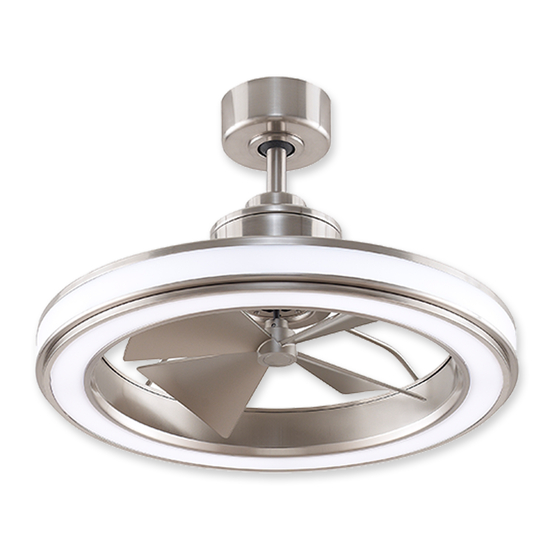
CEILING FAN
GLEAM
™
MODEL #FP8404**
Net Weight 20.90 lbs (9.48 kgs)
Español p. 18
Advertisement
Chapters
Table of Contents

Subscribe to Our Youtube Channel
Related Manuals for Fanimation SHOWROOM GLEAM FP8404 Series


Summary of Contents for Fanimation SHOWROOM GLEAM FP8404 Series
- Page 1 CEILING FAN GLEAM ™ MODEL #FP8404** Español p. 18 ATTACH YOUR RECEIPT HERE AND REGISTER YOUR FAN AT FANIMATION.COM READ AND SAVE THESE INSTRUCTIONS Net Weight 20.90 lbs (9.48 kgs) Serial Number Purchase Date Questions, problems, missing parts? Before returning to your retailer, call our customer...
- Page 2 Important Safety Instructions WARNING: To avoid fire, shock and serious personal injury, follow these instructions. 1. Read your owner’s manual and safety information before installing your new fan. Review the accompanying assembly diagrams. 2. Before servicing or cleaning unit, switch power off at service panel and lock service panel disconnecting means to prevent power from being switched on accidentally.
-
Page 3: Table Of Contents
6. All costs of removal and reinstallation of the fan are the sole responsibility of the owner of the fan and not the store that sold the fan or Fanimation. 7. Fanimation reserves the right to modify or discontinue any product at any time and may substitute any part under this warranty. -
Page 4: Unpacking Instructions
Fanimation. Substitution of parts or accessories not designated for use with this product by Fanimation could result in personal injury or property damage. 1. Check to see that you have received the following parts: NOTE: If you are uncertain of part description, refer to exploded view illustration. -
Page 5: Energy Efficient Use Of Ceiling Fans
8 - 9 feet above the floor for optimal airflow. Consult your down into the occupied space.Remember to adjust your Fanimation Retailer for optional mounting accessories. thermostat when using your ceiling fan - additional energy and dollar savings could be realized with this simple step! Turn Off When Not in the Room Ceiling fans cool people, not rooms. - Page 6 Electrical and Structural Requirements (Continued) Deep box with brace (Figure 3) Paired with a deep box, this hanger is meant to span CEILING JOIST between two joists and takes the place of wooden blocking. WARNING To reduce the risk of fire, electric shock, or personal injury, mount to outlet box marked acceptable for fan support of 15.9 kg (35 lbs) or less and use mounting screws provided with the outlet box.
-
Page 7: How To Assemble Your Ceiling Fan
How to Assemble Your Ceiling Fan 1. Remove the hanger ball portion from the downrod/ hanger ball assembly by loosening the set screw in the hanger ball until the ball falls freely down the downrod. Downrod Remove the pin from the downrod, then remove the hanger ball. - Page 8 How to Assemble Your Ceiling Fan (continued) 5. Route wires and safety cable through motor coupling cover, canopy screw cover and ceiling canopy. (Figure 5) Ceiling Canopy Canopy Screw Motor Coupling Cover Cover Figure 5 6. Reinstall the hanger ball on the downrod as follows. Route the black, white and blue wires and safety cable through the hanger ball.
-
Page 9: How To Hang Your Ceiling Fan
How to Hang Your Ceiling Fan WARNING To avoid possible electrical shock, be sure electricity is turned off at the main fuse box before hanging. (Figure 1) NOTE: If you are not sure if the outlet box is grounded, contact a licensed electrician for advice, as it must be grounded for safe operation. -
Page 10: How To Wire Your Ceiling Fan
How to Wire Your Ceiling Fan NOTE: The remote unit has 32 different code Receiver Unit combinations. To prevent possible interference from or to other remote units, simply change the combination code in the remote and receiver. 1. To set the code on receiver unit, slide dip switches to the same positions as set on the remote. -
Page 11: How To Install Your Canopy Housing
How to Install Your Canopy Housing NOTE: This step is applicable after the neccessary wiring is completed. Remove one of the two shoulder screws in the hanger bracket. Loosen the second shoulder screw without fully removing it. Assemble canopy by rotating key slot in canopy over shoulder screw in hanger bracket. -
Page 12: How To Operate Your Ceiling Fan
How to Operate Your Ceiling Fan IMPORTANT: Using a full range dimmer switch (not included) to control fan speed will damage the fan. To reduce the risk of fire or electrical shock, do not use a full range dimmer switch to control the fan speed. (Figure 1) Restore electrical power to the outlet box by turning the electricity on at the main fuse box. -
Page 13: How To Install Your Remote Control
How to Operate Your Ceiling Fan (continued) 6. If airflow is desired in the opposite direction, turn the fan off and wait for the blades to stop turning. Then slide the reverse switch on top of motor assembly to the opposite position and turn fan on again. -
Page 14: Troubleshooting
3. Tighten the hanger bracket screws to box is not securely fastened. the outlet box, and secure outlet box. 4.NOT ENOUGH AIR 1. If possible, consider using a longer downrod (not included, you can buy MOVEMENT the longer downrod from fanimation.com). -
Page 15: Parts List
Parts List Model No. FP8404** Hanger Bracket Assembly AP255BL Hanger Ball/Downrod Assembly ADR1-45** Ceiling Canopy PG154** C anopy Screw Cover Assembly AP260** Motor Coupling Cover Assembly APPAC1414** Motor Assembly AMA8404** Receiver Unit RCCA04005000 Hand-Held Remote TR500 Hardware Bag Containing: HDWFP8404 Wire Connectors (4) Bag Assembly Safety Cable ** Insert FINISH CODES (Refer to fan model number located on downrod support) -
Page 16: Exploded-View Illustration
Gleam ™ Exploded-View Illustration Figure 1 NOTE: The illustration shown is not to scale or its actual con guration may vary. Product/parts are subject to change without notice. - Page 17 10983 Bennett Parkway Zionsville, IN 46077 Phone: 888-567-2055 Outside U.S.: 317-733-4113 2019/01 V.01 FAX: 866-482-5215 Copyright 2019 Fanimation FANIMATION.COM...
- Page 18 VENTILADOR DE TECHO GLEAM ™ MODELO 8404** ADJUNTE SU RECIBO AQUÍ Y REGISTRE SU VENTILADOR EN FANIMATION.COM LEA Y GUARDE ESTAS INSTRUCCIONES Peso neto 9.48 kg (20.90 lbs) Número de serie Fecha de compra Preguntas, problemas, piezas faltantes? Antes de volver a la tienda, llame a nuestro Departamento de Servicio al Cliente al 1-888-567-2055, 8 a.m.
- Page 19 Instrucciones de seguridad importantes ADVERTENCIA: Siga estas instrucciones para prevenir incendios, descargas eléctricas y lesiones personales graves. Lea el manual del propietario y la información de seguridad antes de instalar su nuevo ventilador. Observe los diagramas de ensamblaje adjuntos. Antes de llevar a cabo el mantenimiento o la limpieza de la unidad, desconecte la electricidad en el panel de servicio y bloquee los medios de desconexión del mismo para evitar que se active accidentalmente.
- Page 20 GARANTÍA LIMITADA DE POR VIDA DEL MOTOR - Si se produjera una falla en alguna de las partes del motor de su ventilador debido a un defecto en los materiales o en la fabricación durante el tiempo de vida del comprador original, Fanimation proporcionará la pieza de repuesto sin cargo una vez que el ventilador defectuoso sea devuelto a nuestro centro de servicios nacional.
-
Page 21: Instrucciones Para El Desempaque
Fanimation específicamente para el mismo. La pag-nant et/ou les accessoires spécifiquement conçus sustitución de piezas o accesorios que Fanimation no designó pour ce produit par Fanimation. La substitution de para usar con este producto podría ocasionar lesiones pièces ou d'accessoires non conçus par Fanimation... -
Page 22: Requisitos Eléctricos Y Estructurales
óptimo. del reloj. Esto produce una suave corriente ascendente, Consulte en su tienda minorista de Fanimation para que obliga al aire cálido que se acumula cerca del techo a obtener accesorios de montaje opcionales. - Page 23 Requisitos eléctricos y estructurales (cont.) Uso del soporte (Figura 3) Conectado a una caja de distribución eléctrica, este colgador Vigas del techo sirve para abarcar el espacio entre dos vigas y ocupar el lugar de bloqueo de la madera. ADVERTENCIA Para reducir el riesgo de incendios, descargas eléctricas o lesiones personales, fije el ventilador a la caja de distribución eléctrica marcada como aceptable para...
- Page 24 Cómo ensamblar el ventilador de techo 1. Extraiga la pieza de la bola colgante de la unidad de la bola colgante / varilla aflojando el tornillo de Pasador presión de la bola colgante hasta que la bola se Varilla libere de la varilla. Retire el pasador del barral y luego extraiga la semiesfera.
- Page 25 Cómo ensamblar el ventilador de techo (cont.) Pase los cables y cable de seguridad a través de la cubierta de unión del motor, la cubierta para el tornillo del capuchón y el capuchón con el lado abierto Capuchón apuntando hacia arriba. (Figura 5) de techo Cubierta del tornillo de la base...
- Page 26 Cómo colgar el ventilador de techo ADVERTENCIA Para evitar una posible descarga eléctrica, asegúrese de cortar la alimentación eléctrica de la caja de fusiblesprincipal antes de colgar el ventilador. (Figura 1) PRINCIPAL CAJA DE FUSIBLES NOTA: Si no está seguro de si la caja de salida tiene conexión a tierra, pida consejo a un electricista certificado, ya que debe tener conexión a tierra para un funcionamiento seguro.
- Page 27 Cómo colgar el ventilador de techo (cont.) 4. Levante cuidadosamente el ventilador y coloque el ensamble de la bola para colgar/varilla en la abrazadera para colgar que acaba de fijar a la caja de salida. Asegúrese de que la ranura de la bola esté alineada con la lengüeta de la abrazadera para colgar.
- Page 28 Cómo realizar la instalación eléctrica del ventilador de techo NOTA: El mando a distancia incluido en este ventilador Unidad del receptor tiene 32 combinaciones diferentes de códigos. Para evitar posibles interferencias desde o hacia otros mandos a distancia, modifique el código de combinación de su transmisor y receptor.
-
Page 29: Cómo Instalar La Carcasa De La Cubierta
Cómo realizar la instalación eléctrica del ventilador de techo (cont.) 3. Una vez realizadas las conexiones, gire los Conductor blanco Conductor verde conductores hacia arriba y, con cuidado, colóquelos del suministro Caja de salida (puesta a tierra) dentro de la caja de salida; con los conductores blancos y homologada verdes hacia un lado y los conductores negros hacia el Suministro... - Page 30 Cómo utilizar su ventilador de techo El uso de un regulador de la intensidad completa (no incluido) para controlar la velocidad del ventilador dañará el dispositivo. Para reducir el riesgo de incendio o descarga eléctrica, no utilice dicho regulador para controlar la velocidad del ventilador.
- Page 31 Cómo utilizar su ventilador de techo (cont.) 5. Funciones del control remoto: (Figura 5) Luz LED del indicador: Velocidad del ventilador Enciende el ventilador y aumenta la velocidad. Enciende el ventilador y disminuye la velocidad. Enciende el ventilador y aumenta la velocidad. Figura 5 Temporizador de apagado automático: Pulse y tanto el ventilador y la iluminación se...
- Page 32 Cómo instalar su mando a distancia 1. Instalación de la placa de la pared: (Figura 1) Fije la placa de la pared usando los dos tornillos suministrados. Figura 1 Mantenimiento PRECAUCIÓN El único mantenimiento necesario para el ventilador de techo es una limpieza periódica. Al llevar a cabo la limpieza, use sólo un cepillo suave o un No utilice solventes para limpiar el ventilador de techo.
-
Page 33: Solución De Problemas
4. NO HAY SUFICIENTE 1. Si es posible, considere el uso de un barral más largo. Por ejemplo (no incluido, usted puede comprar el MOVIMIENTO DE AIRE tiempo de la vara hacia abajo fanimation.com) -
Page 34: Lista De Piezas
Lista de piezas Modelo N.° FP8404** Descripción Pieza # N.° N.° de Ref. AP255BL Unidad del soporte de suspensión ADR1-45** Unidad del barral/de la semiesfera PG154** Capuchón de techo AP260** Cubierta para el tornillo del capuchón APPAC1414** Cubierta de unión del motor Unidad del motor AMA8404** RCCA04005000... -
Page 35: Ilustración Del Despiece
Gleam ™ Ilustración del despiece Figura 1 NOTA La ilustración que se muestra no está hecha a escala y sucguraciónrealy/oterminación puede variar. - Page 36 10983 Bennett Parkway Zionsville, IN 46077 Llame sin cargo al (888) 567-2055 FAX (866) 482-5215 Desde fuera de los EE.UU., llame al (317) 733-4113 2019/01 V.01 Copyright 2019 Fanimation Visite nuestro sitio Web en www.fanimation.com...
Need help?
Do you have a question about the SHOWROOM GLEAM FP8404 Series and is the answer not in the manual?
Questions and answers