Table of Contents
Advertisement
Quick Links
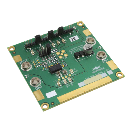
Enpirion EN5367QI DC-DC Converter
w/Integrated Inductor Evaluation Board
Introduction
Thank you for choosing Altera Enpirion power products!
This evaluation board user guide applies to EN5367QI. The EN5367QI is a 6A device.
In addition to this document, you will also need the latest device datasheet.
• The EN5367QI features integrated inductor, power MOSFETS, controller, a bulk
of the compensation network, and protection circuitry against system faults. This
level of integration delivers a substantial reduction in footprint and parts count
over competing solutions. The evaluation board is optimized for engineering ease
of testing through programming options, clip leads, test points etc.
• The EN5367QI features a customer programmable output voltage by means of a
resistor divider. The resistor divider allows the user to set the output voltage to
any value within the range 0.75V to (V
shipped is populated with a 4 resistor divider option. The upper resistor is fixed
and has a phase lead capacitor in parallel. One of 4 lower resistors is selected
with the jumper option for different output voltages to change V
upper resistor and capacitor values and change only the lower resistor.
• This device has no over-voltage protection feature. If making modifications to the
board, we strongly recommend the customer to ensure the feedback loop is truly
closed before powering up the device especially if the load can not withstand the
input voltage.
• The input and output capacitors are X5R or X7R multi-layer ceramic chip
capacitors. The Soft-start capacitor is a small 47nF X7R MLCC. Pads are
available to have multiple input and output capacitors. This allows for evaluation
of performance over a wide range of input/output capacitor combinations.
• The jumper labeled LLM/SYNC pin controls the SYNC pin. LLM (light-load mode)
function is not available on this part. This pin should be pulled LOW if the SYNC
function is not to be used. Do not leave this pin floating or high.
• The jumper labeled VDROOP should be left grounded. This function is not
available on this part.
®
Enpirion
Power Evaluation Board User Guide
-V
IN
DROPOUT
Page 1 of 8
www.altera.com/enpirion
EN5367QI PowerSoC
). The evaluation board, as
, retain the
OUT
Advertisement
Table of Contents

Related Manuals for Altera Enpirion EN5367QI-E


Summary of Contents for Altera Enpirion EN5367QI-E
- Page 1 Inductor Evaluation Board Introduction Thank you for choosing Altera Enpirion power products! This evaluation board user guide applies to EN5367QI. The EN5367QI is a 6A device. In addition to this document, you will also need the latest device datasheet.
- Page 2 Figure 1 and set the supply to the desired voltage. The device disable current may be measured in this configuration. CAUTION: be mindful of the polarity. Even though the evaluation board comes with reverse polarity protection diodes, it may not protect the device under all conditions. Page 2 of 8 www.altera.com/enpirion...
- Page 3 Modes: In order to activate this mode, it may be necessary to a solder a SMA connector at J7. Alternately the input clock signal leads may be directly soldered to the through holes of J7 as shown below. Page 3 of 8 www.altera.com/enpirion...
- Page 4 The added capacitor at the input edge is for high- frequency decoupling of the input cables. The one added at the output edge is meant to represent a typical load decoupling capacitor. Page 4 of 8 www.altera.com/enpirion...
- Page 5 ® Enpirion Power Evaluation Board User Guide EN5367QI PowerSoC Figure 4: Evaluation Board Layout Top and Assembly Layers Page 5 of 8 www.altera.com/enpirion...
- Page 6 1206 VOUT TP20 0805 0805 Use combination 1206/0805 footprint C6-7 TP22 TP25 VOUT PVIN VOUT SCH 05820 PCB 05707 05837 Caps on back 05839 Caps on top and back Figure 5: EN5367QI Evaluation Board Schematic Page 6 of 8 www.altera.com/enpirion...
- Page 7 / output capacitors. For more accurate ripple measurement, please see Enpirion App Note regarding this subject (www.altera.com/enpirion). 4. The board includes a pull-up resistor for the POK signal and ready to monitor the power OK status at clip lead marked POK.
- Page 8 Altera's standard warranty, but reserves the right to make changes to any products and services at any time without notice. Altera assumes no responsibility or liability arising out of the application or use of any information, product, or service described herein except as expressly agreed to in writing by Altera. Altera customers are advised to obtain the latest version of device specifications before relying on any published information and before placing orders for products or services.
Need help?
Do you have a question about the Enpirion EN5367QI-E and is the answer not in the manual?
Questions and answers