Advertisement
Quick Links
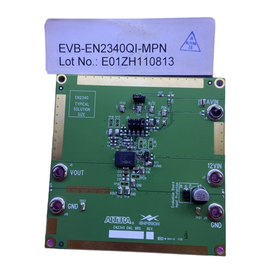
Enpirion EN2340QI DC-DC Converter
w/Integrated Inductor Evaluation Board
Introduction
Thank you for choosing Altera Enpirion power products!
This evaluation board user guide applies to the EN2340 devices mounted on PCB's with
the part number 06905 rev A, and three components on the backside. In addition to this
document, you will also need the latest device datasheet.
• The EN2340QI features integrated inductor, power MOSFETS, controller, a bulk
of the compensation network, and protection circuitry against system faults. This
level of integration delivers a substantial reduction in footprint and parts count
over competing solutions. The evaluation board is optimized for engineering ease
of testing through programming options, clip leads, test points etc.
• The EN2340QI features a customer programmable output voltage by means of a
resistor divider. The resistor divider allows the user to set the output voltage to
any value within the range 0.75V to 5V. The evaluation board, as shipped is
populated with a 4 resistor divider option. The upper resistor is fixed and has a
phase lead capacitor in parallel. One of the 4 lower resistors is selected with the
jumper option for different output voltages. To change V
resistor and capacitor and change only the lower resistor.
• The input and output capacitors are X5R or X7R multi-layer ceramic chip
capacitors. The Soft-start capacitor is a small value X7R MLCC. Pads are
available to have multiple input and output capacitors. This allows for evaluation
of performance over a wide range of input/output capacitor combinations.
• Clip-on terminals are provided for ENA and POK. Banana jacks are provided for
12V
, AVIN, and V
IN
also provided to measure V
• The Enable pin is pre-wired with a resistor divider to PVIN and GND according to
the datasheet recommendation. Enable may also be controlled by applying an
external signal to the ENA clip-on terminal.
®
Enpirion
Power Evaluation Board User Guide
terminals. Several signal and GND clip-on test points are
OUT
, V
, and GND nodes.
IN
OUT
Page 1 of 10
www.altera.com/enpirion
EN2340QI PowerSoC
, retain the upper
OUT
Advertisement

Subscribe to Our Youtube Channel
Related Manuals for Altera Enpirion EN2340QI


Summary of Contents for Altera Enpirion EN2340QI
- Page 1 Inductor Evaluation Board Introduction Thank you for choosing Altera Enpirion power products! This evaluation board user guide applies to the EN2340 devices mounted on PCB’s with the part number 06905 rev A, and three components on the backside. In addition to this document, you will also need the latest device datasheet.
- Page 2 Figure 1), and the component FB1 (to the left of AVIN test point TP28) should not be populated. Please contact Altera Power Applications support if your board does not have these components added on the back side, or if FB1 is still populated.
- Page 3 / output ripple, load transient, drop-out voltage measurements may be conducted at this point. The over current trip level, short circuit protection, under voltage lock out thresholds, temperature coefficient of the output voltage may also be measured in this configuration. Page 3 of 10 www.altera.com/enpirion...
- Page 4 SMA connector at J4. Alternately the input clock signal leads may be directly soldered to the through holes of J4 as shown below. Ext. Clock Figure 3: SMA Connector for External Clock Input Page 4 of 10 www.altera.com/enpirion...
- Page 5 The one added at the output edge is meant to represent a typical load decoupling capacitor. We recommend doing EMI testing in single-supply mode only as this will simplify the test setup. Page 5 of 10 www.altera.com/enpirion...
- Page 6 ® Enpirion Power Evaluation Board User Guide EN2340QI PowerSoC Figure 4: Evaluation Board Top and Assembly Layers. Page 6 of 10 www.altera.com/enpirion...
- Page 7 C3, 10 are 1206/0805 VOUT 12VIN VOUT TP32 TP20 C12, 13, 15, 21 are 1206/0805 TP21 06904 w mods TP22 06905 TP19 Figure 5: EN2340 Evaluation Board Schematic (NR1-NR3 are additional components on the back side) Page 7 of 10 www.altera.com/enpirion...
- Page 8 ≤ 1.2V 31.6kΩ 0.75V < V ≤ 2.0V 33.2kΩ 1.2V < V ≤ 3.0V 36.5kΩ 2.0V < V ≤ 4.0V 39.2kΩ 3.0V < V ≤ 5.0V 41.2kΩ 4.0V < V Table 1: Recommended RCLX values Page 8 of 10 www.altera.com/enpirion...
-
Page 9: Bill Of Materials
TEST POINT SURFACE MOUNT, KEYSTONE 5016 TP21,TP22, TP28,TP32, TP33 TP30, TP31 TEST POINT SURFACE MOUNT, KEYSTONE 5015 EN2340QI QFN 4A RES 10.0K OHM 1/4W 1% AXIAL RES 4.02KOHM 1/4W1% 0805 SMD RES 562 OHM 1/4W 1% AXIAL Page 9 of 10 www.altera.com/enpirion... -
Page 10: Contact Information
Altera's standard warranty, but reserves the right to make changes to any products and services at any time without notice. Altera assumes no responsibility or liability arising out of the application or use of any information, product, or service described herein except as expressly agreed to in writing by Altera. Altera customers are advised to obtain the latest version of device specifications before relying on any published information and before placing orders for products or services.
Need help?
Do you have a question about the Enpirion EN2340QI and is the answer not in the manual?
Questions and answers