Table of Contents
Advertisement
Quick Links
Advertisement
Table of Contents

Subscribe to Our Youtube Channel
Related Manuals for Four-Faith F2103


Summary of Contents for Four-Faith F2103
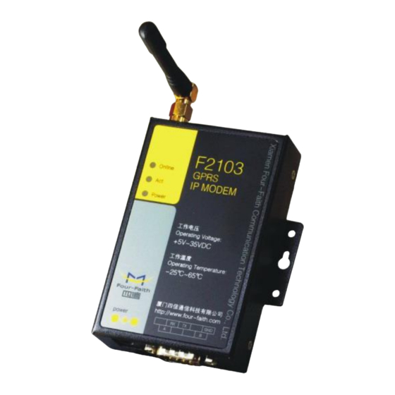
- Page 1 Four-Faith Smart Power Technology Co., Ltd. F2103 GPRS IP MODEM USER MANUAL...
-
Page 2: Table Of Contents
Four-Faith Smart Power Technology Co., Ltd. Contents Contents Chapter 1 Brief Introduction of Product................3 1.1 General........................3 1.2 Features and Benefits..................3 1.3 Working Principle....................4 1.4 Specifications..................... 4 Chapter 2 Installation Introduction.................. 6 2.1 General........................6 2.2 Encasement List....................6 2.3 Installation and Cable Connection..............6 2.4 Power........................ -
Page 3: Chapter 1 Brief Introduction Of Product
1.1 General Power range: DC 5~35V Stability and Reliability F2103 GPRS IP MODEM is a kind of cellular terminal device that provides data Support hardware and software WDT transfer function by public GPRS network. Support auto recovery mechanism, including online detect, auto redial when... -
Page 4: Working Principle
Four-Faith Smart Power Technology Co., Ltd. Support dynamic domain name(DDNS) and IP access to data center Compliant to GSM phase 2/2+ Design with standard TCP/IP protocol stack GPRS class 10, class 12(optional) Support APN/VPDN Bandwidth 85.6Kbps TX power GSM850/900: <33dBm... - Page 5 Four-Faith Smart Power Technology Co., Ltd. Operating 95% ( Non-condensing) Humidity Power Input Item Content Standard Power DC 12V/1.5A Power Range DC 5~35V Consumption <250mA (12V) Physical Characteristics Item Content Housing Iron, providing IP30 protection Dimensions 91x58.5x22 mm Weight 205g...
-
Page 6: Chapter 2 Installation Introduction
Four-Faith Smart Power Technology Co., Ltd. Chapter 2 Installation Introduction 2.3 Installation and Cable Connection Dimension : (unit: mm) 2.1 General The IP MODEM must be installed correctly to make it work properly. Warning: Forbid to install the IP MODEM when powered! 2.2 Encasement List... -
Page 7: Power
Four-Faith Smart Power Technology Co., Ltd. Warning: Forbid to install SIM/UIM card when powered! Installation of antenna: Screw the SMA male pin of the antenna to the female SMA outlet of the IP The signal connection of the RS485 data cable is as follows: MODEM tightly. -
Page 8: Indicator Lights Introduction
Four-Faith Smart Power Technology Co., Ltd. 2.5 Indicator Lights Introduction The IP MODEM provides three indicator lights: “Power”, “ACT”, “Online”. Indicator State Introduction Light Power IP MODEM is powered on IP MODEM is powered off BLINK Data is communicating No data... -
Page 9: Chapter 3 Configuration
Four-Faith Smart Power Technology Co., Ltd. make IP MODEM enter configure state, please refer to appendix. Chapter 3 Configuration The following describes how to configure IP MODEM with the configure software tool. At the same time, it gives out the corresponding AT command of each configuration item. -
Page 10: Re-Power Ip Modem
Four-Faith Smart Power Technology Co., Ltd. display 3.5 Configuration “Port(COM1) Has Opened,Please Re-Power the IP MODEM, Waiting IP MODEM Enter Configure State...” 3.5.1 Data Service Center Settings 3.4 Re-power IP MODEM Settings on this page are the parameters related to Data Service Center(DSC). - Page 11 Four-Faith Smart Power Technology Co., Ltd. AT command: AT+PTSEC=xxx AT+SVRCNT=x xxx: The port value x: Data Service Center number Note: every AT command is terminated with a enter character. ◆Multi DSC Configuration ◆Main Center Addr+Port: IP Address and Port of the Main DSC, It’s better to set the port greater than 1024.
-
Page 12: Ip Modem Settings
Four-Faith Smart Power Technology Co., Ltd. AT+IPAD2=166.111.8.238 AT+PORT2=5001 ◆ Main and Backup Center DNS Server When the IP MODEM work in Multi Data Service Center method and the centers use domain name, 2~5 DNS server is used to resolve center 2~5 correspondingly. - Page 13 Four-Faith Smart Power Technology Co., Ltd. PROT : Heartbeat packet with TCP protocol, Data transmission with TCP protocol, transmission. But in some circumstances, it’s important to reduce wireless data flow. heartbeat packet and application data transmission are in the same TCP To realize this function, the software can makes IP MODEM into sleep state in idle connection.
- Page 14 Four-Faith Smart Power Technology Co., Ltd. AT+DEBUG=x --- 600 bps x : the debug level value 1200 --- 1200 bps 2400 --- 2400 bps Note: Only there is some problem to the IP MODEM, It’s necessary to set this 4800...
- Page 15 Four-Faith Smart Power Technology Co., Ltd. AT Command: ◆ Bytes Interval AT+RETMAIN=x x : 0 or 1 ◆ Device ID The time interval used to determine whether the serial data frame transmission has completed, IP MODEM will send the serial data to the center when two bytes transmit time interval larger than this item value.
-
Page 16: Other Settings
Four-Faith Smart Power Technology Co., Ltd. ◆ Custom Heartbeat String xxx:times try to connect to the center “Reconnect Time Interval” AT Command: AT+RDLWT=xxx This item is only valid when the WorkMode is TCST. It’s the self defined heartbeat xxx: the sleep time until next retry. - Page 17 Four-Faith Smart Power Technology Co., Ltd. ◆ Network AT+CENT=xxx xxx: call center phone number of ISP ◆ SMS Center APN: access point name. Your local SMS center number Username: username to login the ISP network. Password: password to login the ISP network...
- Page 18 Four-Faith Smart Power Technology Co., Ltd. This item is only valid when the “Trigger Type” is CTRL or MIXD. In this trigger type, IP MODEM will keeps in idle state until it receives the trigger phone call, then it This item is valid only when the “Trigger Type” is DATA or MIXD, IP MODEM will connect to the center.
-
Page 19: Functions
Four-Faith Smart Power Technology Co., Ltd. ◆ Factory setting Restore to factory settings This item is valid only when the “Data Center Number” is greater than 1. ◆ Show Config When one of the configured data center lost connection, IP MODEM will try to... -
Page 20: Work State Switch
Four-Faith Smart Power Technology Co., Ltd. Restore settings from a previous saved configure file Appendix 3.7 Work State Switch The following steps describe how to make IP MODEM enter configure state with the Windows XP Hyper Terminal. 1. Press “Start” ”Programs” ”Accessories” ”Communications” ”Hyper Terminal”... - Page 21 Four-Faith Smart Power Technology Co., Ltd. 3. Choose the correct COM port which connect to IP MODEM, choose “OK” 4. Configure the serial port parameters as following, choose “OK” Bits per second: 115200 5. Complete Hyper Terminal operation, It runs as following...
- Page 22 Four-Faith Smart Power Technology Co., Ltd. Re-power IP MODEM, put mouse focus on the Hyper Terminal and press “s” key continuously until IP MODEM enter configure state as following 7. IP MODEM has entered configure state, you can configure the parameters through...
Need help?
Do you have a question about the F2103 and is the answer not in the manual?
Questions and answers