
Related Manuals for Four-Faith F2816 V2


Summary of Contents for Four-Faith F2816 V2
- Page 1 FOUR FAITH F2816 V2 IP MODEM USER MANUAL V2.0.1 Xiamen Four-Faith Communication Technology Co., Ltd. https://en.four-faith.com...
- Page 2 All contents in the files are protected by copyright law, and all copyrights are reserved by Xiamen Four-Faith Communication Technology Co., Ltd. Without written permission, all commercial use of the files from Four-Faith are forbidden, such as copy, distribute, reproduce the files, etc., but non-commercial purpose, downloaded or printed by individual (all files shall be not revised, and the copyright and other proprietorship notice shall be reserved) are welcome.
- Page 3 Intended USE With high-speed cellular interface (3G and beyond), the F2816 V2 modem are highly versatile, reliable and rugged modem designed for M2M industry in the IoT industry chain.
- Page 4 devices are to be used only according to the instructions described in its manual. Faultless and safe operation of the devices can be guaranteed only if the transport, storage, operation and handling of the devices is appropriate. This also applies to the maintenance of the products.
- Page 5 use and user should avoid moisture or high humidity environment; preferable use only indoors or inside of proper isolation against harsh weather conditions. Do not pull the antenna or power supply cable. Please attach or detach by holding the connector.
- Page 6 power supply. This so-called inrush current can be several times higher than normal current consumption but will last only few ten milliseconds. For proper operation it is crucial to assure that the power supply has output power rated to higher than the maximum power consumption of the device and that the power supply can handle short inrush currents properly.
- Page 7 Increase the separation between the equipment and receiver Connect the equipment into an outlet on a circuit different from that to which the receiver is connected Consult the dealer or an experienced radio technician for help Check settings (APN, SSID) and SIM cards Accessories Device is supplied to customers either in bulk packages or in a cardboard box with following content...
-
Page 8: Table Of Contents
Contents Chapter 1 Brief Introduction of Product..................... 9 1.1 General..........................9 1.2 Features and Benefits......................9 1.3 Working Principle........................10 1.4 Specifications........................12 Chapter 2 Installation Introduction....................15 2.1 General..........................15 2.2 Encasement List........................15 2.3 Installation and Cable Connection..................15 2.4 Power...........................17 2.5 Indicator Lights Introduction.................... -
Page 9: Chapter 1 Brief Introduction Of Product
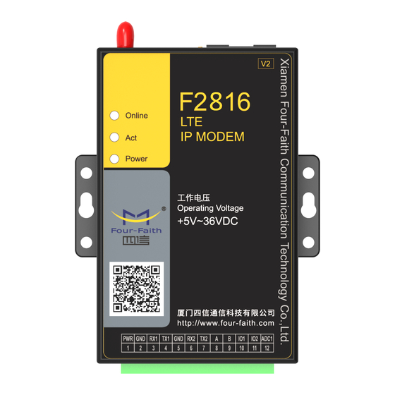
Chapter 1 Brief Introduction of Product 1.1 General F2816V2 series IP MODEM is a kind of cellular terminal device that provides data transfer by public cellular network. It adopts high-powered industrial 32 bits CPU and embedded real time operating system. It supports RS232 and RS485 port that can conveniently and transparently connect one device to a cellular network, allowing you to connect to your existing serial devices with only basic configuration. -
Page 10: Working Principle
High-powered industrial cellular module High-powered industrial 32 bits CPU Support low power consumption mode, including multi-sleep and trigger modes to reduce the power consumption Housing: iron, providing IP30 protection. Power range: DC 5~36V Stability and Reliability ... - Page 11 SRAM& FLASH WDT Module Indicator Lights Antenna Cellular RS232/RS485/RS422 Module Module SIM/UIM Interface Power Module User Interface Figure1-2 IP Modem principle chart F2x16 consists of the following major components: - A controlling unit made of a CPU (industrial 32-bit processor) - WDT module - Cellular module - RS232/RS485 serial module...
-
Page 12: Specifications
Multi-center,and also many common protocol,include Modbus、Http、MQTT. All the above grants the modem to be secure and reliable quite above its essential requirements. 1.4 Specifications Cellular Specification Item Content F2816 V2 FDD-LTE IP MODEM LTE: B1/B3/B5/B7/B8/B20/B28/B38/B40/B41 (other bands optional) Standard WCDMA: B1/B5/B8 EDGE/GPRS/GSM 850/900/1800MHz Bandwidth... - Page 13 DC-HSPA+: Download 42Mbps, Upload 5.76Mbps HSPA+: Download 21Mbps, Upload 5.76Mbps HSDPA: Download 7.2Mbps, Upload 5.76Mbps UMTS: 384Kbps TX power <23dBm RX sensitivity <-93.3dBm Hardware System Item Content Industrial 32 bits CPU FLASH 512KB(Extendable) SRAM 256KB Interface Type Item Content Serial 2 RS232 and 1 RS485 , 15KV ESD protection Data bits: 5, 6 ,7, 8 Stop bits: 1, 1.5, 2...
- Page 14 Communication 45~165mA@12VDC (2G:45~55 mA3G:80~165 mA 4G:75~95mA ) 105~365mA@5VDC (2G:105~115 mA 3G:165~365 mA 4G:150~200mA ) Standby 35~50 mA@12VDC 55~105 mA@5VDC Sleep 3mA@12VDC 6mA@5VDC Physical Characteristics Item Content Housing Iron, providing IP30 protection Dimensions 91x58.5x22 mm Weight 205g Environmental Limits Item Content Operating -35~+75ºC (-22~+167℉) Temperature...
-
Page 15: Chapter 2 Installation Introduction
Chapter 2 Installation Introduction 2.1 General The IP MODEM must be installed correctly to make it work properly. Warning: Forbid to install the IP MODEM when powered! 2.2 Encasement List Name Quantity Remark IP MODEM host Cellular Antenna Power adapter RS232 data cable optional RS485 data cable... - Page 16 Firstly power off the IP MODEM, and press the button of the SIM/UIM card outlet with a needle object. Then the SIM/UIM card sheath will flick out at once. Put SIM/UIM card into the card sheath (Pay attention to put the side which has metal point outside), and insert card sheath back to the SIM/UIM card outlet.
-
Page 17: Power
Black &White Anode Black Cathode RS232 Cable Cable Color DB9-M Pin Number Brown Pin 2 Blue Pin 3 Black Pin 5 RS485 Cable Cable Color Signal definition RS485(A) Black RS485(B) Power adapter and communication cable connection 2.4 Power The power range of the IP MODEM is DC 5~36V We recommend user to use the standard DC 12V/0.5A power adaptor. - Page 18 Indicator State Introduction Power IP MODEM is powered on IP MODEM is powered off BLINK Data is communicating No data Online IP MODEM has logged on network IP MODEM hasn’t logged on network Page 18 of 56...
-
Page 19: Chapter 3 Configuration
Chapter 3 Configuration 3.1 Connection Before configuration, It’s necessary to connect the IP MODEM with the PC by the shipped RS232 or RS232-485 conversion cable as following. 3.2 Configuration Introduction There are two ways to configure the IP MODEM: Configuration software tool: All the settings are configured through the shipped software tool. -
Page 20: Ip Modem's Parameters Configuration
same time, it gives out the corresponding AT command of each configuration item. 3.3 IP Modem’s Parameters Configuration 3.3.1 Run the Configure Tools The “Serial” area shows the current serial port settings. To configure IP MODEM, please choose the correct serial port which connects to IP MODEM, and the baud-rate is 115200 with no parity, then open the serial port. - Page 21 After Re-power IP MODEM, The configure tool will make it enter configure state. At the same time, the software will load current settings from IP MODEM and displays on the right configure columns. It’s now ready to configure. Note:To enter configure state for 4G device may need more time. It is about 40 seconds. 3.3.3 Work Mode 3.3.3.1 App protocol The IP Modem can be configured many communication protocols to adapt for different...
- Page 22 transmission is transparent. DCTCP This protocol is used in electric power field, with TCP protocol. PhoneNo. Phone number DCUDP This protocol is used in electric power field, with UDP protocol PhoneNo. Phone number TRNS The device work as MODEM for sending/receiving SMS, CSD and GPRS dialing. SMSCLI IP MODEM work as a SMS DTU.
- Page 23 Pone No 2nd Group Pone No 3rd Group Pone No 4th Group Pone No 5th Group Show Phone Number If send phone number to serial port or not Hex To Text If convert HEX data to ASCII data or not Send SMS Hex If send SMS with Hex format or not SMSSER...
- Page 24 Device ID ID number for the device. 8 characters Hex To Text If convert HEX data to ASCII data or not Send SMS Hex This item is only valid when the Work Mode is PROT. If this item is set to No, IP MODEM will transfer meaning to 0xfd and 0xfe.
- Page 25 Data Format Text: the flowing items are Text format Hex:the flowing items are Hex format Login Packet Login packet Login Reply Login packet respond Heartbeat Packet Heart packet Heartbeat Reply Heartbeat packet respond Custom protocol:Server mode It supports TCP and udp server. Base Protocol TCP or UDP Listen Port...
- Page 26 SMS Phone No. Trigger phone number. If it is empty, sms received from any phone no. can trigger the device SMS Password The content of SMS to trigger. If it is empty, any content of sms can trigger the device CTRL Make IP MODEM online through a phone call to IP MODEM.
- Page 27 Sleep/Wakeup Made the IP Modem sleep or wake up depended on the I/O state Set I/O port to trigger the IP Modem to sleep or wake up MIXD The combination of SMSD, CTRL, DATA. IP MODEM will be online when meet one of these three trigger methods.
-
Page 28: Data Service Center Settings
Debug Port Port 2:debug info send to port 2 485:debug info send to RS485 3.3.3.4 Clear Serial Buffer When open “clearing Serial buffer” function, serial port data before connecting to the network will not be sent to the center 3.4 Data Service Center Settings Settings on this page are the parameters related to Data Service Center (DSC). - Page 29 Back To Main Server This item is only valid when you set “Data Center Number” as 1. In this mode, IP MODEM will switch to backup center when main center have problems. If this item is set to 1 , IP MODEM will check whether the main center work fine timely.
-
Page 30: Serial Port
ICMP Check Enable or Disable Dest Address The destination address of ICMP packet to send Check Interval(s) The interval should not be too small. 60 is recommended(in second) Check Times >= 3 times 3.5 Serial port IP MODEM support three individual serial ports, Port1, Port2 and RS485. All the three ports can enter configuration state. -
Page 31: Io Function
56000 --- 56000 bps 57600 --- 57600 bps 115200 --- 115200 bps Property:Databit, Parity, Stopbit 8N1 --- 8 Databit, No parity, 1 Stopbit 8E1 --- 8 Databit, Even parity, 1 Stopbit 8O1 --- 8 Databit, Odd parity, 1 Stopbit Bind: Center1: the data from the port send to center 1 Center2: the data from the port send to center 3 Center3: the data from the port send to center 3... -
Page 32: Dial
Report Type Query/Time/IO Trigger Command Random string Data Format Text or Hex High leve Status indicator string,when port is high level,will report it to DSC Low level Status indicator string,when port is low level,will report it to DSC 3.6.2 Analog input Disable or enable ADC Port support COM/GPRS/ SMS... -
Page 33: Global Parameters
CDMA/EVDO card/card PPP Auth AUTO,PAP and CHAP QueryNetMode Search the network mode for the 4G network Net Mode Net Mode AUTO EVDO WCDMA TD-SCDMA CDMA 3.7.2 PPP Redial Re-dial Interval(s) The interval between ppp dial in second Dial Retry Times max times of ppp dial failure 3.7.3 DNS Parameters When the DSC Internet access uses domain name, It’s necessary to set DNS server resolving the... -
Page 34: Device Manage
transmission has completed, IP MODEM will send the serial data to the center when two bytes transmit time interval larger than this item value.(in milliseconds) TCP Max packet length 3.8.2 Action for data send fail When data send to server fail(there are not response from server),IP modem will take a failed action after setting delay. -
Page 35: Operation
Protocol TCP or UDP Service Address manage center server address Port manage center server port 3.9.2 Manage by SMS Configure the IP Modem by SMS SMS Configure Enable or Disable Configure Password The password for SMS Configure Manage Phone No. If it is empty, any number can configure the IP Modem Parameters. -
Page 36: Chapter 4 Application Case
Chapter 4 Application Case 4.1 Modem connect to data center In this application,the client can communicate with the server side by gprs network. IP modem configuration Configure server IP and port: Fill in the APN from your simcard provider: Repower modem,wait it connected to server. Page 36 of 56... -
Page 37: Remote Management Platform
Then you can send data to test the communication between modem with data sever(here use Netassit software to simulate data server) 4.2 Remote management platform You need enable Device management setting in modem: Page 37 of 56... -
Page 38: Sms To Configure Modem
If need remote management service,pls contact Four-Faith engineer for support. 4.3 SMS to configure modem You can send SMS to configure modem via mobile phone Step one Enable SMS Manage function in modem: set SMS sender's phone number, the password is the one set in the modem.it can be digit or letter. -
Page 39: Update Firmware Via Download Tool
Detail AT command pls check in Appendix 2. 4.4 Update firmware via download tool If you need upgarde firmware,pls contact Four-Faith sale or technical support to get the download tool and lattest firmware file. Download tool: Follow the steps to upgrade: connect your laptop with modem via serial cable choose the com and set correct baudrate,and find the firmware version you save in... -
Page 40: Save Modem Logs
When download is complete, you will find the cost time (21 sec). 4.5 Save modem logs When using modem and meet any problems,you can save logs and send it to Four-Faith technical support. In order to get detail log information,you should set debug level to “ level 2”first:... -
Page 41: Modbus Protocol For Gpio&Adc Acquisition
4.6 Modbus Protocol for GPIO&ADC Acquisition 4.6.1 The Way of Cable Connection. Analog input a. Single-cable: Connect the analog output of the sensor to the analog input(ADC) of F2X16 directly. b. Double-cable: Connect the positive of analog output of the sensor to the analog input(ADC) of F2X16, and connect the ground wire to GND(PIN2) of F2114. - Page 42 IO1: Digital input/output 0---3.3V IO2: Digital input/output 0---3.3V ADC: current input 4--20MA *Changes can be made in hardware to make ADC as voltage input. For IO1&IO2: Disable---- Don’t use IO port Input--- Use IO as digital input port. Output---Use IO as digital output port. Indication---When connect to data center, it will output a high level to indicate data transmission You can choose the port for each port: RS232-1----The value will be sent to com1, you can check the value in RS232-1.
- Page 43 You can choose the protocol, and you also need set the query commands. Modbus--you can use our modbus to query the value. Custom---you can use the command of your own. Set modbus address in Global param: Page 43 of 56...
- Page 44 4.6.3 The modbus command for F2X16 IO& ADC: Query digital Input To read IO1 status(digital input) Request: 01 02 00 00 00 01 B9 CA Response:01 02 01 01 60 48 (IO1 is high level) Response:01 02 01 00 A1 88 (IO1 is low level) To read IO2 status(digital input) Request: 01 02 00 01 00 01 E8 0A Response:01 02 01 01 60 48 (IO2 is high level)
-
Page 45: Mqtt Test
Query ADC To read ADC status(current input) Request: 01 04 00 02 00 01 90 0A Response:01 04 02 00 64 B8 DB Notes of the modbus commands. Take the command 01 04 00 01 00 01 60 0A for example. Response 01 04 02 00 B8 B9 42 The acquisition value in HEX. -
Page 46: Mtcp/Mrtu
You can download MQTTBox as another client, parametersconfiguration as the following: Clients will connect to MQTT server if parameters are configured correctly,you can send data to test communication from MQTT Box: The send topic of the MQTTBOX is set to the Receive topic of the terminal, and the Receive topic is set to the send topic of the modem, and data can be sent to each other at this time. - Page 47 Modbus RTU frame format: Slave ID: 1 bytes, used to identify modbus frame transmitted on the TCP/IP stack Function Code: 1 bytes, coding range 1-255 Data: N*1 bytes, length and content are determined by the type of Function code Error Check: 2 bytes, CRC check, used to check whether the received data is correct.
- Page 48 Transaction ID:2 bytes, Modbus request/respond transaction identifier. Protocol ID:2 bytes,0=Modbus protocol Length: follow-up bytes, include Unit ID and data field Unit ID:1 bytes, the ID of remote slave station Example 1: Modbus TCP(Data Center send to modem): 00 01 00 00 00 06 01 04 00 00 00 01 (06 length, 01 is modbus address, 04 is function code, 00 00 00 01 is the register start address 2 bytes + the number of registers 2 bytes) Modbus RTU(recieve in serial port of modem): 01 04 00 00 00 01...
-
Page 49: Http Protocol Test
4.9 HTTP Protocol Test Modem can work in HTTP mode,HTTP Request Mode you can choose GET or POST.as the following setting. You need configure data center address before test. Page 49 of 56... - Page 50 POST mode: If Modem dial successfully and connected to http server,Serial data will be packaged with HTTP format then sent to the server. HTTP data: POST HTTP/1.1 Host: 120.42.46.98:5650 User-Agent: Go-http-client/1.1 Content-Length: 9 Content-Type: application/json 6666666 After sending data,modem should recieve response within 5 second,respond format as: HTTP/1.1 200 When modem recieve data,will transfer application data(OK) to serial port,as the following figure show:...
-
Page 51: Clear Serial Buffer
GET mode: HTTP data: GET 6666666 HTTP/1.1 Host: 120.42.46.98:5650 User-Agent: Go-http-client/1.1 If data send to server successfully,modem aslo will recieve”ok” in serail port,as the following figure show: If no data is sent, modem will send an HTTP request packet according to configured interval. The format is the previous format, but the application data is missing. - Page 52 Page 52 of 56...
- Page 53 Appendix 1 The following steps describe how to make IP MODEM enter configure state with the Windows XP Hyper Terminal. 1. Press “Start””Programs””Accessories””Communications””Hyper Terminal” 2. Input connection name, choose “OK” 3. Choose the correct COM port which connect to IP MODEM, choose “OK” 4.
- Page 54 Bits per second: 115200 Data bits: 8 Parity: None Stop bits: 1 Flow control: None 5. Complete Hyper Terminal operation, It runs as following 6. Re-power IP MODEM, put mouse focus on the Hyper Terminal and press “s” key Page 54 of 56...
- Page 55 continuously until IP MODEM enter configure state as following 7. IP MODEM has entered configure state, you can configure the parameters through AT command. Page 55 of 56...
- Page 56 Appendix 2 AT command for DTU setting: AT+APN=<apn> Set Access Point Name AT+CENT=<center no.> Set Center call number AT+USERNAME=<user id> Set PPP Authentication User AT+PASSWORD=<password> Set PPP Authentication Password AT+SVRCNT=< Total Servers> Set Total Servers AT+IPAD=<Server's Ip Address> Set Server's Ip or Domain AT+IPADn=<Aux Server's Ip Address(n=1,2..4)>...
Need help?
Do you have a question about the F2816 V2 and is the answer not in the manual?
Questions and answers