
Related Manuals for Vivotek SUPREME MD9582-H


Summary of Contents for Vivotek SUPREME MD9582-H
- Page 1 MD9582-H Mobile Dome Camera User ’s Manual 5MP • Mobile Surveillance • IP67 • IK10 • NEMA 4X • Day & Night • WDR Pro • Smart Stream III • SNV II • 20M Smart IR Rev. 1.0...
-
Page 2: Table Of Contents
Ready to Use ................................ 30 Accessing the Network Camera ........................... Using Web Browsers ............................33 Using RTSP Players ............................. 36 Using 3GPP-compatible Mobile Devices ......................37 Using VIVOTEK Recording Software ........................38 Main Page ................................Client Settings ................................. Configuration ................................ -
Page 3: Overview
VIVOTEK Applications > Audio detection ....................... 142 Applications > Shock detection ....................... 144 Applications > Package management - a.k.a., VADP (VIVOTEK Application Development Platform) ... 145 Recording > Recording settings ......................148 Local storage > Storage management ..................... 153 Storage > Content management ......................155 Appendix .............................. -
Page 4: Revision History
2. If powered by a power adapter, the adapter should be properly grounded. 3. Maintenance and repair work must always be carried out by qualified technical personnel. 4. Disconnect power from the unit when performing a maintenance task. 5. Please contact VIVOTEK's certified dealers for power adapters. 4 - User's Manual... - Page 5 VIVOTEK NOTE: Camera Hardware Preventative Maintenance: 1. Visual inspection of all major components including accessories, cabling and connections where accessible for signs of deterioration or damage. 2. Check and clean cameras, lenses and housings inside and out as needed. •...
- Page 6 Cross-Site Request Forgery (CSRF) protection in Configuration > Security > Miscellaneous. • For up-to-date documentation of URL commands, please go to VIVOTEK’s website, register an account with a business mail address and submit for authorization for SDK in Support > Downloads > SDK.
-
Page 7: Package Contents
VIVOTEK Package Contents ■ MD9582-H ■ T10 torx screwdriver, desiccant bag, 4-pin and 2-pin terminals, screws, and hex nuts. ■ Quick Installation Guide & alignment sticker. WARNING: 1. IR lights emit from ths product. 2. Use appropriate shielding or eye protection. -
Page 8: Dimension Drawing
VIVOTEK Dimension Drawing Screw Pack 8 - User's Manual... -
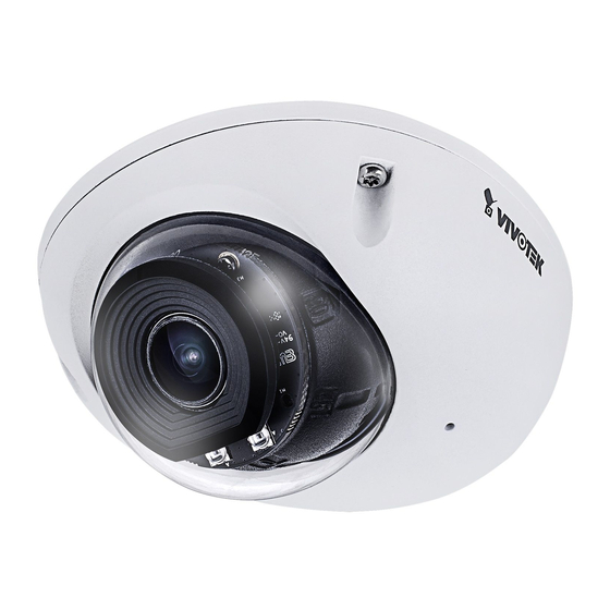
Page 9: Physical Description
VIVOTEK Physical Description Outer View Microphone Lens Inner View Reset button IR LEDs MicroSD card LEDs socket Lens gimbal User's Manual - 9... - Page 10 VIVOTEK NOTE: Some of the suffix syntax used in model naming are listed below: w/ heater for extreme weather Focal length w/ number w/ Remote focus lens w/ PoE repeater w/ High Dynamic Range functionality IMPORTANT: PoE 37V-57V 0.16A-0.11A 10 - User's Manual...
-
Page 11: Hardware Installation
VIVOTEK Hardware Installation IMPORTANT: If you plan to use the Human Detection feature, make sure you measure the height of your camera. The height information is important for the accuracy of the video analytics results. Some of the other perspective information are automatically collected by the onboard S-sensor. - Page 12 VIVOTEK 1. Jot down the camera's MAC address for later reference. XXXXXX 0002D10766AD 2. Loosen the T10 anti-tamper screws to temporarily remove the top cover. 3. If preferred, connect the digital output, digital input, or audio line-in wires. Name DO+ (5V, max. 50mA) DI+ (any input <30V)
- Page 13 VIVOTEK M12 Ethernet D-coded RxData+ TxData+ RxData- TxData- 4. Connect the ground wire to the chassis ground. to chassis ground 5. Install a MicroSD card if onboard storage is preferred. User's Manual - 13...
- Page 14 VIVOTEK 6. Attach the alignment sticker to a preferred location. Aim the shooting direction on the sticker at a direction you prefer. Drill holes on the wall or ceiling to install the plasic anchors. Anchors may not be necessary for installation on different materials.
- Page 15 VIVOTEK The combo cable is made of fire-retardant materials. It may be rigid when fitting it through the vehicle panel. Note the bend radius of the cable as shown below: Cable BEND RADIUS HL1: min. bend radius 67.5mm (9x O.D.) during installation 37.5mm (5x O.D.) during operation...
- Page 16 VIVOTEK 8. Pull the combo cable through the routing hole. 9. Secure the camera to the mount surface by driving 3 screws and tighten with hex nuts. 16 - User's Manual...
-
Page 17: Software Installation
Software Installation 11. Install the Shepherd utility, which helps you locate and configure your Network Camera in the local network. If your camera comes without the CD, go to VIVOTEK’s website, and locate the utility in the Downloads > Software page. - Page 18 11-2. The program will conduct an analysis of your network environment. 11-3. The program will search for all VIVOTEK network devices on the same LAN. 11-4. After a brief search, the installer window will prompt. Click on the MAC and model name that matches the one printed on the product label.
- Page 19 VIVOTEK Forceful Password Configuration 12. The first time you log in to the camera, the firmware will prompt for a password configuration for security concerns. Since your camera is used for the first time, there is no password. Enter “root” as the user name, and nothting for the password.
- Page 20 VIVOTEK Some, but not all special ASCII characters are supported: !, $, %, -, ., @, ^, _, and ~. You can use them in the password combination. Another prompt will request for the password you configured. Enter the password and then you can start configure your camera and see the live view.
- Page 21 VIVOTEK 13. With a live video, you can adjust the camera lens tilt or rotation angle. ±180° ±90° User's Manual - 21...
- Page 22 VIVOTEK Note that the numeric markings on the lens gimbal can be used to indicate the degrees of rotation. 0°: 180°: bottom For example, if the camera is mounted on a vertical surface, and the lens is turned 90 degree to accommodate the mount position, the 90 degree marking should be displayed at the center of the lens gimbal.
- Page 23 VIVOTEK 14. When you acquire an optimal view, replace the desiccant bag at the center of the camera. 15. Remove the protective sheet from the top of lens cover. User's Manual - 23...
- Page 24 VIVOTEK See below for the effective IR illumination range and coverage 70° 100° 24 - User's Manual...
- Page 25 VIVOTEK In addition to mechanically turning the shooting angles, you may also digitally turn the orientation of the image. 90° 270° User's Manual - 25...
- Page 26 VIVOTEK DI/DO Diagram 1. The DO+ pin provides a 5V output, and the max. load is 50mA. 2. The max. voltage for DO- pins is 30VDC (External power). In order to control AC devices, the following diagram can be taken into consideration.
- Page 27 VIVOTEK Wet contact with external DC power source to supply a relay. Switch DC 0V External DC power External AC power with Protected Earth Relay External Device Dry contact and using camera’s DO+ to supply a relay. Switch External AC power...
- Page 28 VIVOTEK LED Definitions Item LED status Description Steady Powered and system booting, or network failed LED off Power off Green LED off Network is disconnected Steady Green LED blinks every 1 Connected to network sec. Green LED blinks every 1 sec. and Upgrading firmware blinks consecutively every 0.15 sec.
-
Page 29: Network Deployment
VIVOTEK Network Deployment General Connection (PoE) When using a PoE-enabled switch The Network Camera is PoE-compliant, allowing transmission of power and data via a sin- gle Ethernet cable. Follow the below illustration to connect the Network Camera to a PoE- enabled switch via Ethernet cable. -
Page 30: Ready To Use
VIVOTEK Ready to Use 1. A browser session with the Network Camera should prompt as shown below. 2. You should be able to see live video from your camera. You may also install the 32-channel recording software from the software CD in a deployment consisting of multiple cameras. - Page 31 VIVOTEK Internet connection via a router Before setting up the Network Camera over the Internet, make sure you have a router and follow the steps below. 1. Connect your Network Camera behind a router, the Internet environment is illustrated below.
- Page 32 For more information with network configuration options (such as that of streaming ports), please refer to Configuration > Network Settings. VIVOTEK also provides the automatic port forwarding feature as an NAT traversal function with the precondition that your router must support the UPnP port forwarding feature.
-
Page 33: Accessing The Network Camera
3. Live video will be displayed in your web browser. 4. If it is the first time installing the VIVOTEK network camera, an information bar will prompt as shown below. Follow the instructions to install the required plug-in on your computer. - Page 34 VIVOTEK ► By default, the Network Camera is not password-protected. To prevent unauthorized access, it is highly recommended to set a password for the Network Camera. For more information about how to enable password protection, please refer to Security on page 107.
- Page 35 VIVOTEK IMPORTANT: • Currently the Network Camera utilizes a 32-bit ActiveX plugin. You CAN NOT open a management/view session with the camera using a 64-bit IE browser. • If you encounter this problem, try execute the Iexplore.exe program from C:\Windows\ SysWOW64.
-
Page 36: Using Rtsp Players
VIVOTEK Using RTSP Players To view the streaming media using RTSP players, you can use one of the following players that support RTSP streaming. VLC media player VLC media player mpegable Player 1. Launch the RTSP player. pvPlayer 2. Choose File > Open URL. A URL dialog box will pop up. -
Page 37: Using 3Gpp-Compatible Mobile Devices
VIVOTEK Using 3GPP-compatible Mobile Devices To view the streaming media through 3GPP-compatible mobile devices, make sure the Network Camera can be accessed over the Internet. For more information on how to set up the Network Camera over the Internet, please refer to Setup the Network Camera over the Internet on page To utilize this feature, please check the following settings on your Network Camera: 1. -
Page 38: Using Vivotek Recording Software
Network Camera to the Channel list. For detailed information about how to use the recording software, please refer to the user’s manual of the software or download it from http://www.vivotek.com. Tips: 1. If you encounter problems with displaying live view or the onscreen plug-in control, you may try to remove the plug-ins that might have been installed on your computer. -
Page 39: Main Page
VIVOTEK Main Page This chapter explains the layout of the main page. It is composed of the following sections: VIVOTEK INC. Logo, Host Name, Camera Control Area, Configuration Area, Menu, and Live Video Window. Resize Buttons VIVOTEK INC. Host Name... - Page 40 VIVOTEK Configuration Area Client Settings: Click this button to access the client setting page. For more information, please refer to Client Settings on page 44. Configuration: Click this button to access the configuration page of the Network Camera. It is suggested that a password be applied to the Network Camera so that only the administrator can configure the Network Camera.
- Page 41 VIVOTEK PTZ Panel: This Network Camera supports “digital“ (e-PTZ) pan/tilt/zoom control, which allows roaming a smaller view frame within a large view frame. Please refer to PTZ settiings on page 122 for detailed information. Global View: Click on this item to display the Global View window. The Global View window contains a full view image (the largest frame size of the captured video) and a floating frame (the viewing region of the current video stream).
- Page 42 VIVOTEK Video Control Buttons: Depending on the Network Camera model and Network Camera configuration, some buttons may not be available. Snapshot: Click this button to capture and save still images. The captured images will be displayed in a pop-up window. Right-click the image and choose Save Picture As to save it in JPEG (*.jpg) or BMP (*.bmp) format.
- Page 43 VIVOTEK ■ The following window is displayed when the video mode is set to MJPEG: Video Title Time 2018/07/25 17:08:56 Video (HTTP-V) Title and Time Video 17:08:56 2018/07/25 Video Control Buttons Video Title: The video title can be configured. For more information, please refer to Media > Image on page 68.
-
Page 44: Client Settings
VIVOTEK Client Settings This chapter explains how to select the stream transmission mode and saving options on the local computer. When completed with the settings on this page, click Save on the page bottom to enable the settings. H.265/H.264 Protocol Options H.264 Protocol Options... - Page 45 VIVOTEK MP4 Saving Options Users can record live video as they are watching it by clicking Start MP4 Recording on the main page. Here, you can specify the storage destination and file name. Folder: Specify a storage destination on your PC for the recorded video files. The location can be changed.
- Page 46 VIVOTEK Joystick settings Enable Joystick Connect a joystick to a USB port on your management computer. Supported by the plug-in (Microsoft’s DirectX), once the plug-in for the web console is loaded, it will automatically detect if there is any joystick on the computer. The joystick should work properly without installing any other driver or software.
- Page 47 VIVOTEK Buttons Configuration In the Button Configuration window, the left column shows the actions you can assign, and the right column shows the functional buttons and assigned actions. The number of buttons may differ from different joysticks. Please follow the steps below to configure your joystick buttons: 1.
- Page 48 VIVOTEK Buttons Configuration Click the Configure Buttons button, a window will prompt as shown below. Please follow the steps below to configure your joystick buttons: 1. Select a button number from the Button # pull-down menu. Tips: If you are not sure of the locations of each button, use the Properties window in the Game Controllers utility.
-
Page 49: Configuration
Click Configuration on the main page to enter the camera setting pages. Note that only Administrators can access the configuration page. VIVOTEK provides an easy-to-use user interface that helps you set up your network camera with minimal effort. In order to simplify the user interface, detailed information will be hidden unless you click on the function item. -
Page 50: System > General Settings
VIVOTEK System > General settings This section explains how to configure the basic settings for the Network Camera, such as the host name and system time. It is composed of the following two columns: System, and System Time. When finished with the settings on this page, click Save at the bottom of the page to enable the settings. - Page 51 VIVOTEK System time Keep current date and time: Select this option to preserve the current date and time of the Network Camera. The Network Camera’s internal real-time clock maintains the date and time even when the power of the system is turned off.
- Page 52 VIVOTEK Western Argentina Summer Time (WARST) is 3 hours behind the prime meridian all year. There is a dummy fall-back transition on December 31 at 25:00 daylight saving time (i.e., 24:00 standard time, equivalent to January 1 at 00:00 standard time), and a simultaneous spring-forward transition on January 1 at 00:00 standard time, so daylight saving time is in effect all year and the initial WART is a placeholder.
-
Page 53: System > Homepage Layout
Theme Options (the second tab on this page). The settings will be displayed automatically in this Preview field. The following shows the homepage using the default settings: ■ Hide Powered by VIVOTEK: If you check this item, it will be removed from the homepage. Logo graph Here you can change the logo that is placed at the top of your homepage. - Page 54 VIVOTEK Theme Options Here you can change the color of your homepage layout. There are three types of preset patterns for you to choose from. The new layout will simultaneously appear in the Preview filed. Click Save to enable the settings.
- Page 55 VIVOTEK ■ Follow the steps below to set up the customized homepage: 1. Click Custom on the left column. 2. Click the field where you want to change the color on the right column. Color Selector Custom Pattern 3. The palette window will pop up as shown below.
-
Page 56: System > Logs
VIVOTEK System > Logs This section explains how to configure the Network Camera to send the system log to a remote server as backup. Log server settings Follow the steps below to set up the remote log: 1. Select Enable remote log. - Page 57 You can install the included VAST recording software, which provides an Event Management function group for delivering event messages via emails, GSM short messages, onscreen event panel, or to trigger an alarm, etc. For more information, refer to the VAST User Manual. VIVOTEK Network Cameras Internet 3G Cell phone HTTP...
- Page 58 VIVOTEK Access log Access log displays the access time and IP address of all viewers (including operators and administrators) in a chronological order. The access log is stored in the Network Camera’s buffer area and will be overwritten when reaching a certain limit.
-
Page 59: System > Parameters
VIVOTEK System > Parameters The View Parameters page lists the entire system’s parameters. If you need technical assistance, please provide the information listed on this page. User's Manual - 59... -
Page 60: System > Maintenance
Note: Do not power off the Network Camera during the upgrade! Follow the steps below to upgrade the firmware: 1. Download the latest firmware file from the VIVOTEK website. The file is in .pkg file format. 2. Click Browse… and locate the firmware file. - Page 61 VIVOTEK General settings > Restore This feature allows you to restore the Network Camera to factory default settings. Network: Select this option to retain the Network Type settings (please refer to Network Type on page 89). Daylight Saving Time: Select this option to retain the Daylight Saving Time settings (please refer to Import/Export files below on this page).
- Page 62 VIVOTEK The following message is displayed when attempting to upload an incorrect file format. Export language file: Click to export language strings. VIVOTEK provides nine languages: English, Deutsch, Español, Français, Italiano, 日本語, Português, 簡体中文, and 繁體中文 . Update custom language file: Click Browse… and specify your own custom language file to upload.
-
Page 63: Media > Image
VIVOTEK Media > Image This section explains how to configure the image settings of the Network Camera. It is composed of the following columns: General settings, IR control, Image settings, Exposure, and Privacy mask. The Focus window is available only for models that come with motorized lens. - Page 64 VIVOTEK Video orientation: Flip - vertically reflect the display of the live video; Mirror - horizontally reflect the display of the live video. Select both options if the Network Camera is installed upside-down (e.g., on the ceiling) to correct the image orientation. Please note that if you have preset locations, those locations will be cleared after flip/mirror setting.
- Page 65 VIVOTEK IR cut filter With a removable IR-cut filter, this Network Camera can automatically remove the filter to let Infrared light pass into the sensor during low light conditions. ■ Auto mode (The Day/Night Exposure Profile will not be available if Auto mode is selected) The Network Camera automatically removes the filter by judging the level of ambient light.
- Page 66 VIVOTEK Illuminators Turn on built-in IR illuminator in night mode Select this to turn on the camera’s onboard IR illuminator when the camera detects low light condition and enters the night mode. Turn on external IR illuminator in night mode Select this to turn on the external IR illuminator when the camera detects low light condition and enters the night mode.
- Page 67 VIVOTEK Tips: If there is an object in close proximity, the IR lights reflected back from it can mislead the Smart IR’s calculation of light level. To solve this problem, you can place an “Exposure Exclude” window on an unavoidable object in the Exposure setting window.
- Page 68 VIVOTEK Image settings On this page, you can tune the White balance and Image adjustment. Sensor Setting 2: For special situations Sensor Setting 1: For normal situations White balance: Adjust the value for the best color temperature. ■ You may follow the steps below to adjust the white balance to the best color temperature.
- Page 69 VIVOTEK Highlight mask ■ Strong light sources will be masked from the scene, and the image contrast will be strengthened. This function is useful to prevent the spot-light effects in a high dynamic scene. False color may be observed around the edges of strong light sources.
- Page 70 VIVOTEK Exposure On this page, you can set the Exposure measurement window, Exposure level, Exposure mode, Exposure time, Gain control, and Day/Night mode settings. You can configure two sets of Exposure settings: one for normal situations, the other for special situations, such as the day/night/schedule mode.
- Page 71 VIVOTEK The inclusive window refers to the “weighted window“; the exclusive window refers to “ignored window“. It adopts the weighted averages method to calculate the value. The inclusive windows have a higher priority. You can overlap these windows, and, if you place an exclusive window within a larger inclusive window, the exclusive part of the overlapped windows will be deducted from the inclusive window.
- Page 72 VIVOTEK Exposure control: ■ Exposure level: You can manually set the Exposure level, which ranges from -2.0 to +2.0 (dark to bright). You can click and drag the semi-circular pointers on the Exposure time and Gain control slide bars to specify a range of shutter time and Gain control values within which the camera can automatically tune to an optimal imaging result.
- Page 73 VIVOTEK You can click Restore to recall the original settings without incorporating the changes. When completed with the settings on this page, click Save to enable the settings. If you want to configure another sensor setting for day/night/schedule mode, please click Profile to open the Profile of exposure settings page as shown below.
- Page 74 VIVOTEK Privacy mask Click Privacy Mask to open the settings page. On this page, you can block out sensitive zones to address privacy concerns. ■ To configure privacy mask windows, 1. Click New to add a new window. 2. You can use 4 mouse clicks to create a new masking window, which is recommended to be at least twice the size of the object (height and width) you want to cover.
-
Page 75: Media > Video
VIVOTEK Media > Video Mode The applicable video modes include: ■ 5MP (max. 30fps): This is the full resolution at 5 megapixels in a 4:3 screen aspect ratio. ■ 4MP (16:9) (max. 30fps): At the 16:9 aspect ratio, the usable resolution is slightly reduced to 4MP. -
Page 76: Media > Video
VIVOTEK Media > Video Stream settings This Network Camera supports multiple streams with frame sizes ranging from 480 x 352 to 2560 x 1920 pixels The definition of multiple streams: ■ Stream 1: Users can define the "Region of Interest" (viewing region) and the "Output Frame Size"... -
Page 77: Media > Video
VIVOTEK Please follow the steps below to set up those settings for a stream: 1. Select a stream for which you want to set up the viewing region. 2. Select a Region of Interest from the drop-down list. The floating frame, the same as the one in the Gloabl View window on the home page, will resize accordingly. - Page 78 VIVOTEK Click the stream item to display the detailed information. The maximum frame size will follow your settings in the above Viewing Window sections. This Network Camera provides real-time H.265, H.264 and MJPEG compression standards (Triple Codec) for real-time viewing. If the H.265...
- Page 79 VIVOTEK The frame rate will decrease if you select a higher resolution. ■ Intra frame period Determine how often for firmware to plant an I frame. The shorter the duration, the more likely you will get better video quality, but at the cost of higher network bandwidth consumption. Select the intra frame period from the following durations: 1/4 second, 1/2 second, 1 second, 2 seconds, 3 seconds, and 4 seconds.
- Page 80 VIVOTEK With the H.265 codec in an optimal scenario and when Dynamic Intra frame is combined with the Smart Stream function, an 80% of bandwidth saving can be achieved compared with using H.264 without enabling these bandwidth-saving features. ■ Smart FPS In a static scene, the algorithm puts old frames in queue when no motions occur in scene.
- Page 81 VIVOTEK • Smart codec: Smart codec effectively reduces the quality of the whole or the non- interested areas on a screen and therefore reduces the bandwidth consumed. You can manually specify the video quality for the foreground and the background areas.
- Page 82 VIVOTEK As the result, the lower screen is constantly displayed in high details, while the upper half is transmitted using a lower-quality format. Although the upper half is transmitted using a lower quality format, you still have an awareness of what is happening on the whole screen.
- Page 83 VIVOTEK Bit rate control ■ Constrained bit rate: A complex scene generally produces a larger file size, meaning that higher bandwidth will be needed for data transmission. The bandwidth utilization is configurable to match a selected level, resulting in mutable video quality performance. The bit rates...
- Page 84 VIVOTEK Fixed quality: On the other hand, if Fixed quality is selected, all frames are transmitted with the same quality; bandwidth utilization is therefore unpredictable. The video quality can be adjusted to the following settings: Medium, Standard, Good, Detailed, and Excellent.
- Page 85 VIVOTEK If the JPEG mode is selected, the Network Camera sends consecutive JPEG images to the client, producing a moving effect similar to a filmstrip. Every single JPEG image transmitted guarantees the same image quality, which in turn comes at the expense of variable bandwidth usage. Because the media contents are a combination of JPEG images, no audio data is transmitted to the client.
-
Page 86: Media > Audio
VIVOTEK Media > Audio Audio Settings Mute: Select this option to disable audio transmission from the Network Camera to all clients. Note that if muted, no audio data will be transmitted even if audio transmission is enabled on the Client Settings page. -
Page 87: Media Profiles
VIVOTEK Media profiles You can configure a different video stream for each of the 3 default profiles, Max. view, Recording, Live view, and App. The related video stream information will display, including stream number, resolution, codec used, frame rate, etc. The Multicast port number, and address for video, audio, and Metadata configuration will also be listed. -
Page 88: Network > General Settings
Use fixed IP address: Select this option to manually assign a static IP address to the Network Camera. 1. You can make use of VIVOTEK Installation Wizard 2 on the software CD to easily set up the Network Camera on LAN. Please refer to Software Installation on page 22 for details. - Page 89 VIVOTEK Primary DNS: The primary domain name server that translates hostnames into IP addresses. Secondary DNS: Secondary domain name server that backups the Primary DNS. Primary WINS server: The primary WINS server that maintains the database of computer names and IP addresses.
- Page 90 VIVOTEK NOTE: ► If the default ports are already used by other devices connected to the same router, the Network Camera will select other ports for the Network Camera. ► If UPnP is not supported by your router, you will see the following message: Error: Router does not support UPnP port forwarding.
- Page 91 VIVOTEK 4. In the Networking Services dialog box, select Universal Plug and Play and click OK. 5. Click Next in the following window. 6. Click Finish. UPnP is enabled. ► How does UPnP work? UPnP networking technology provides automatic IP configuration and dynamic discovery of devices added to a network.
- Page 92 VIVOTEK Enable IPv6 Select this option and click Save to enable IPv6 settings. Please note that this only works if your network environment and hardware equipment support ® IPv6. The browser should be Microsoft Internet Explorer 6.5, Mozilla Firefox 3.0 or above.
- Page 93 VIVOTEK Please follow the steps below to link to an IPv6 address: 1. Open your web browser. 2. Enter the link-global or link-local IPv6 address in the address bar of your web browser. 3. The format should be: http://[2001:0c08:2500:0002:0202:d1ff:fe04:65f4]/ IPv6 address 4.
- Page 94 VIVOTEK 94 - User's Manual...
-
Page 95: Network > Streaming Protocols
VIVOTEK Network > Streaming protocols HTTP streaming To utilize HTTP authentication, make sure that your have set a password for the Network Camera first; please refer to Security > User account on page 107 for details. Authentication: Depending on your network security requirements, the Network Camera provides two types of security settings for an HTTP transaction: basic and digest. - Page 96 VIVOTEK URL command -- http://<ip address>:<http port>/<access name for stream 1, 2, 3> For example, when the Access name for stream 2 is set to video2.mjpg: 1. Launch Mozilla Firefox or Netscape. 2. Type the above URL command in the address bar. Press Enter.
- Page 97 VIVOTEK Authentication: Depending on your network security requirements, the Network Camera provides three types of security settings for streaming via RTSP protocol: disable, basic, and digest. basic authentication is selected, the password is sent in plain text format, but there can be digest potential risks of it being intercepted.
- Page 98 Unrestricted in scope IMPORTANT: The Multicast metadata port is utilized by VIVOTEK VADP modules to transfer video analytics results, PTZ stream, textual data, and event messages between the camera and the client side running and observing the video analysis. If your client side computer is located outside the local network, you may need to open the associated TCP port on routers and firewall.
- Page 99 IP address, to have a fixed host and domain name. Express link Express Link is a free service provided by VIVOTEK server, which allows users to register a domain name for a network device. One URL can only be mapped to one MAC address.
- Page 100 DDNS: Dynamic domain name service Enable DDNS: Select this option to enable the DDNS setting. Provider: Select a DDNS provider from the provider drop-down list. VIVOTEK offers Safe100.net, a free dynamic domain name service, to VIVOTEK customers. It is recommended that you register Safe100.net to access VIVOTEK’s Network Cameras from the...
- Page 101 4. Select Enable DDNS and click Save to enable the setting. ■ CustomSafe100 VIVOTEK offers documents to establish a CustomSafe100 DDNS server for distributors and system integrators. You can use CustomSafe100 to register a dynamic domain name if your distributor or system integrators offer such services.
- Page 102 VIVOTEK Network > QoS (Quality of Service) Quality of Service refers to a resource reservation control mechanism, which guarantees a certain quality to different services on the network. Quality of service guarantees are important if the network capacity is insufficient, especially for real-time streaming multimedia applications. Quality can be defined as, for instance, a maintained level of bit rate, low latency, no packet dropping, etc.
- Page 103 VIVOTEK QoS/DSCP (the DiffServ model) DSCP-ECN defines QoS at Layer 3 (Network Layer). The Differentiated Services (DiffServ) model is based on packet marking and router queuing disciplines. The marking is done by adding a field to the IP header, called the DSCP (Differentiated Services Codepoint). This is a 6-bit field that provides 64 different class IDs.
-
Page 104: Network > Snmp (Simple Network Management Protocol)
VIVOTEK Network > SNMP (Simple Network Management Protocol) This section explains how to use the SNMP on the network camera. The Simple Network Management Protocol is an application layer protocol that facilitates the exchange of management information between network devices. It helps network administrators to remotely manage network devices and find, solve network problems with ease. -
Page 105: Network > Ftp
FTP function. You can disable the FTP server function when it is not in use. FTP port: The FTP server allows the user to save recorded video clips. You can utilize VIVOTEK's Shepherd utility to upgrade the firmware via FTP server. By default, the FTP port is set to 21. It can also be assigned to another port number between 1025 and 65535. -
Page 106: Bonjour
VIVOTEK Bonjour To access the camera from a Mac computer, go to Safari, click on Bonjour and select the camera from a drop-down list. You can go to Safari > Preferences to enter your user name and password, and provide the root password the first time you access the camera. -
Page 107: Security > User Accounts
VIVOTEK Security > User accounts This section explains how to enable password protection and create multiple accounts. Account management The administrator account name is “root”, which is permanent and can not be deleted. If you want to add more accounts in the Account management window, please apply the password for the “root”... - Page 108 VIVOTEK Privilege management Digital Output & PTZ control: You can modify the management privilege as operators or viewers. Select or de-select the checkboxes, and then click Save to enable the settings. If you give Viewers the privilege, Operators will also have the ability to control the Network Camera through the main page.
-
Page 109: Security > Https (Hypertext Transfer Protocol Over Ssl)
VIVOTEK Security > HTTPS (Hypertext Transfer Protocol over SSL) This section explains how to enable authentication and encrypted communication over SSL (Secure Socket Layer). It helps protect streaming data transmission over the Internet on higher security level. Create and Install Certificate Method Before using HTTPS for communication with the Network Camera, a Certificate must be created first. - Page 110 VIVOTEK 5. Click Save to preserve your configuration, and your current session with the camera will change to the encrypted connection. 6. If your web session does not automatically change to an encrypted HTTPS session, click Home to return to the main page. Change the URL address from “http://” to “https://“ in the address bar and press Enter on your keyboard.
- Page 111 VIVOTEK Create certificate request and install 1. Select the option from the Method pull-down menu. 2. Click Create certificate to proceed. 3. The following information will show up in a pop-up window after clicking Create. Then click Save to generate the certificate request.
- Page 112 VIVOTEK 5. Look for a trusted certificate authority, such as Symantec’s VeriSign Authentication Services, that issues digital certificates. Sign in and purchase the SSL certification service. Copy the certificate request from your request prompt and paste it in the CA’s signing request window. Proceed with the rest of the process as CA’s instructions on their webpage.
- Page 113 VIVOTEK 7. Open a new edit, paste the certificate contents, and press ENTER at the end of the contents to add an empty line. 8. Convert file format from DOS to UNIX. Open File menu > Conversions > DOS to Unix.
- Page 114 VIVOTEK 9. Save the edit using the “.crt” extension, using a file name like “CAcert.crt.” 10. Return to the original firmware session, use the Browse button to locate the crt certificate file, and click Upload to enable the certification. 114 - User's Manual...
- Page 115 VIVOTEK Note that 11. When the certifice file is successfully loaded, its status will be stated as Active. a certificate must have been created and installed before you can click on the “Save" button for the configuration to take effect.
-
Page 116: Security > Access List
VIVOTEK Security > Access List This section explains how to control access permission by verifying the client PC’s IP address. General Settings Maximum number of concurrent streaming connection(s) limited to: Simultaneous live viewing for 1~10 clients (including stream 1 to stream 3). The default value is 10. If you modify the value and click Save, all current connections will be disconnected and automatically attempt to re-link (IE Explorer). - Page 117 VIVOTEK ■ Refresh: Click this button to refresh all current connections. ■ Add to deny list: You can select entries from the Connection Status list and add them to the Deny List to deny access. Please note that those checked connections will only be disconnected temporarily and will automatically try to re-link again (IE Explorer).
- Page 118 VIVOTEK There are three types of rules: Single: This rule allows the user to add an IP address to the Allowed/Denied list. For example: 192.168.2.1 Network: This rule allows the user to assign a network address and corresponding subnet mask to the Allow/Deny List.
- Page 119 Authentication server (usually a RADIUS server): Checks the client certificate and decides whether to accept the end user’s access request. ■ VIVOTEK Network Cameras support two types of EAP methods to perform authentication: EAP- PEAP and EAP-TLS. Please follow the steps below to enable 802.1x settings: 1.
- Page 120 VIVOTEK 3. When all settings are complete, move the Network Camera to the protected LAN by connecting it to an 802.1x enabled switch. The devices will then start the authentication automatically. NOTE: ► The authentication process for 802.1x: 1. The Certificate Authority (CA) provides the required signed certificates to the Network Camera (the supplicant) and the RADIUS Server (the authentication server).
- Page 121 VIVOTEK Security > Miscellaneous The embedded TrendMicro utitlity provides the protection against Cross-Site Request Forgery. Cross-site request forgery is also known as one-click attack or session riding and is abbreviated as CSRF. CSRF is a type of malicious exploit of a website, in this case, the camera.
-
Page 122: Ptz > Ptz Settings
VIVOTEK PTZ > PTZ settings This section explains how to control the Network Camera’s Pan/Tilt/Zoom operation. Digital: Control the e-PTZ operation. Within a field of view,it allows users to quickly move the focus to a target area for close-up viewing without physically moving the camera. - Page 123 VIVOTEK Home page in the E-PTZ Mode ■ The e-Preset Positions will also be displayed on the home page. Select one from the drop-down list, and the Network Camera will move to the selected position. ■ If you have set up different preset positions for different streams, you can select one of the video streams to display its separate preset positions.
- Page 124 VIVOTEK Patrol settings You can select some preset positions for the Network Camera to patrol. Please follow the steps below to set up a patrol schedule: 1. Select the preset locations on the list, and click 2. The selected preset locations will be displayed on the Patrol locations list.
- Page 125 VIVOTEK NOTE: • The Preset Positions will also be displayed on the Home page. Select one from the Go to menu, and the Network Camera will move to the selected preset position. • Click Patrol: The Network Camera will patrol along the selected positions repeatedly.
-
Page 126: Event > Event Settings
VIVOTEK Event > Event settings This section explains how to configure the Network Camera to respond to particular situations (event). A typical application is that when a motion is detected, the Network Camera sends buffered images to an FTP server or e-mail address as notifications. Click on Help, there is an illustration shown in the pop-up window explaining that an event can be triggered by many sources, such as motion detection or external digital input devices. - Page 127 VIVOTEK ■ Event name: Enter a name for the event setting. ■ Enable this event: Select this checkbox to enable the event setting. ■ Priority: Select the relative importance of this event (High, Normal, or Low). Events with a higher priority setting will be executed first.
- Page 128 VIVOTEK ■ Audio detection A preset threshold can be configured with an external microphone as the trigger to system event. The triggering condition can be an input exceeding or falling below a threshold. Audio detection can take place as a complement to motion detection or as a method to detect activities not covered by the camera's view.
- Page 129 VIVOTEK Once the triggers are configured, they will be listed under the VADP option. 3. Action Define the actions to be performed by the Network Camera when a trigger is activated. ■ Trigger digital output for seconds Select this option to turn on the external digital output device when a trigger is activated. Specify the length of the trigger interval in the text box.
- Page 130 VIVOTEK Add server It is necessary to configure the server and media settings so that the Network Camera will know what action to take (such as which server to send the media files to) when a trigger is activated. Click server to open the server setting window.
- Page 131 VIVOTEK To verify if the email settings are correctly configured, click Test. The result will be shown in a pop-up window. If successful, you will also receive an email indicating the result. Click Save server to enable the settings. Note that after you configure the first event server, the new event server will automatically display on the Server list.
- Page 132 VIVOTEK ■ Passive mode Most firewalls do not accept new connections initiated from external requests. If the FTP server supports passive mode, select this option to enable passive mode FTP and allow data transmission to pass through the firewall. The firmware default has the Passive mode checkbox selected.
- Page 133 VIVOTEK Network storage: Select to send the media files to a networked storage when a trigger is activated. Please refer to NAS server on page 151 for details. Note that only one NAS server can be configured. Click Save server to enable the settings.
- Page 134 VIVOTEK Click 20190120 to open the directory: The format is: HH (24r) Click to open the file list for that hour 2019/01/20 2019/01/20 Click to go back to the previous Click to delete level of the directory selected items Click to delete all...
- Page 135 VIVOTEK Add media Add media Click to open the media setting window. You can specify the type of media that will be sent when a trigger is activated. A total of 5 media settings can be configured. There are three choices of media types available: Snapshot, Video Clip, and System log.
- Page 136 VIVOTEK ■ Add date and time suffix to the file name Select this option to add a date/time suffix to the file name. For example: Snapshot_20190513_100341 File name prefix Date and time suffix The format is: YYYYMMDD_HHMMSS Click Save media to enable the settings.
- Page 137 VIVOTEK ■ Maximum file size Specify the maximum file size allowed. Some users may need to stitch the video clips together when searching and packing up forensic evidence. ■ File name prefix Enter the text that will be appended to the front of the file name.
- Page 138 VIVOTEK In the Event settings column, the Servers and Medias you configured will be listed; please make sure the Event -> Status is indicated as ON, in order to enable the event triggering action. When completed, click the Save event button to enable the settings and click Close to exit Event Settings page.
-
Page 139: Applications > Motion Detection
VIVOTEK Applications > Motion detection The camera comes with a Smart Motion Detection utility as its pre-loaded VCA package. Please refer to its User Guide for more information: http://download.vivotek.com/downloadfile/solutions/vadp/smart-motion-detection-manual_ en.pdf. Click on Configuration > Applications > Motion detection. The Smart Motion utility will be automatically started. -
Page 140: Applications > Di And Do
VIVOTEK Applications > DI and DO Digital input: Select High or Low as the Normal status for the digital input connection. Connect the digital input pin of the Network Camera to an external device to detect the current connection status. -
Page 141: Applications > Tampering Detection
VIVOTEK Applications > Tampering detection This section explains how to set up camera tamper detection. With tamper detection, the camera is capable of detecting incidents such as redirection, blocking or defocusing, or even spray paint. Please follow the steps below to set up the camera tamper detection function: 1. -
Page 142: Applications > Audio Detection
VIVOTEK Applications > Audio detection Audio detection, along with video motion detection, is applicable in the following scenarios: 1. Detection of activities not covered by camera view, e.g., a loud input by gun shots or breaking a door/window. 2. A usually noisy environment, such as a factory, suddenly becomes quiet due to a breakdown of machines. - Page 143 VIVOTEK You can use the Profile window to configure a different Audio detection setting. For example, a place can be noisy in the day time and become very quiet in the night. 1. Click on the Enable this profile checkbox. Once the Audio detection window is opened, the current sound input will be interactively indicated by a fluctuating yellow wave diagram.
-
Page 144: Applications > Shock Detection
VIVOTEK Applications > Shock detection The camera comes with a shock accelerometer. The shock sensor can detect impacts to the camera. For example, when a person deliberately tries to destroy the camera, the camera can report the event to the administrator. -
Page 145: Applications > Package Management - A.k.a., Vadp (Vivotek Application Development Platform)
Users can store and execute VIVOTEK's or 3rd-party software modules onto the camera's flash memory or SD card. These software modules can apply in video analysis for intelligent video applications such as license plate recognition, object counting, or as an agent for edge recording, etc. - Page 146 VIVOTEK To utilize a software module, acquire the software package and click Browse and Upload buttons. The screen message for a successful upload is shown below: To start a module, select the checkcircle in front, and click the Start button.
- Page 147 VIVOTEK On the License page, register and activate the license for using VIVOTEK's VADP modules. You should acquire the license key elsewhere, and manually upload to the network camera. Follow the onscreen instruction on VIVOTEK's website for the registration procedure.
-
Page 148: Recording > Recording Settings
VIVOTEK Recording > Recording settings This section explains how to configure the recording settings for the Network Camera. Recording Settings Insert your SD card and click here to test NOTE: ► Please remember to format your SD card via the camera’s web console (in the Local storage . - Page 149 VIVOTEK If you enable adaptive recording on a camera, only when an event is triggered on Camera A will the server record the full frame rate streaming data; otherwise, it will only request the I frame data during normal monitoring, thus effectively saves bandwidths and storage space.
- Page 150 VIVOTEK 2. Destination You can select the SD card or network storage (NAS) for the recorded video files. If you have not configured a NAS server, see details in the following. NAS server Click Add NAS server to open the server setting window and follow the steps below to set up: 1.
- Page 151 VIVOTEK If successful, you will receive a test.txt file on the network storage server. 3. Enter a server name. 4. Click Save to complete the settings and click Close to exit the page. ■ Capacity: You can choose either the entire free space available or limit the reserved space. The recording size limit must be larger than the reserved amount for cyclic recording.
- Page 152 VIVOTEK Event f you want to enable recording notification, please click to configure event triggering settings. Please refer to Event > Event settings on page 126 for more details. When completed, select Enable this recording. Click Save to enable the setting and click Close to exit this page.
-
Page 153: Local Storage > Storage Management
VIVOTEK Local storage > Storage management NOTE: • It is recommended to turn OFF the recording activity before you remove an SD card from the camera. • The lifespan of an SD card is limited. Regular replacement of the SD card can be necessary. - Page 154 VIVOTEK SD card control ■ Enable cyclic storage: Check this item if you want to enable cyclic recording. When the maximum capacity is reached, the oldest file will be overwritten by the latest one. ■ Enable automatic disk cleanup: Check this item and enter the number of days you wish to retain a file.
-
Page 155: Storage > Content Management
VIVOTEK Storage > Content management This section explains how to manage the content of recorded videos on the Network Camera. Here you can search and view the records and view the searched results. Searching and Viewing the Records This column allows the user to set up search criteria for recorded data. If you do not select any criteria and click Search button, all recorded data will be listed in the Search Results column. - Page 156 VIVOTEK Search Results The following is an example of search results. There are four columns: Trigger time, Media type, Trigger type, and Locked. Click to sort the search results in either direction. Numbers of entries displayed on one page Click to open a live view ■...
- Page 157 VIVOTEK ■ Lock/Unlock: Select the checkbox in front of a desired search result, then click this button. The selected items will become Locked, which will not be deleted during cyclic recording. You can click again to unlock the selections. For example:...
-
Page 158: Appendix
VIVOTEK Appendix URL Commands for the Network Camera 1. Overview For some customers who already have their own web site or web control application, the Network Camera/Video Server can be easily integrated through URL syntax. This section specifies the external HTTP-based application programming interface. - Page 159 VIVOTEK © 2020 VIVOTEK INC. All Right Reserved 3. General CGI URL Syntax and Parameters CGI parameters are written in lower-case and as one word without any underscores or other separators. When the CGI request includes internal camera parameters, these parameters must be written exactly as they are named in the camera or video server.
- Page 160 VIVOTEK © 2020 VIVOTEK INC. All Right Reserved 4. Security Level SECURITY LEVEL SUB-DIRECTORY DESCRIPTION anonymous Unprotected. 1 [view] viewer Can view, listen, and talk to camera. 4 [operator] operator Operator access rights can modify most of the camera’s parameters except some privileges and network options.
- Page 161 VIVOTEK © 2020 VIVOTEK INC. All Right Reserved 5. Get Server Parameter Values Note: The access right depends on the URL directory. Method: GET/POST Syntax: http://<servername>/cgi-bin/anonymous/getparam.cgi?[<parameter>] [&<parameter>…] http://<servername>/cgi-bin/viewer/getparam.cgi?[<parameter>] [&<parameter>…] http://<servername>/cgi-bin/operator/getparam.cgi?[<parameter>] [&<parameter>…] http://<servername>/cgi-bin/admin/getparam.cgi?[<parameter>] [&<parameter>…] Where the <parameter> should be <group>[_<name>] or <group>[.<name>]. If you do not specify any parameters, all the parameters on the server will be returned.
- Page 162 VIVOTEK © 2020 VIVOTEK INC. All Right Reserved http://192.168.0.123/cgi-bin/admin/getparam.cgi?network_ipaddress Response: HTTP/1.0 200 OK\r\n Content-Type: text/html\r\n Context-Length: 33\r\n \r\n network.ipaddress=192.168.0.123\r\n 162 - User's Manual...
- Page 163 VIVOTEK © 2020 VIVOTEK INC. All Right Reserved 6. Set Server Parameter Values Note: The access right depends on the URL directory. Method: GET/POST Syntax: http://<servername>/cgi-bin/anonymous/setparam.cgi? <parameter>=<value> [&<parameter>=<value>…][&return=<return page>] http://<servername>/cgi-bin/viewer/setparam.cgi? <parameter>=<value> [&<parameter>=<value>…][&return=<return page>] http://<servername>/cgi-bin/operator/setparam.cgi? <parameter>=<value> [&<parameter>=<value>…][&return=<return page>] http://<servername>/cgi-bin/admin/setparam.cgi? <parameter>=<value> [&<parameter>=<value>…][&return=<return page>]...
- Page 164 VIVOTEK © 2020 VIVOTEK INC. All Right Reserved [<parameter pair>] Only the parameters that you set and are readable will be returned. Example: Set the IP address of server to 192.168.0.123: Request: http://myserver/cgi-bin/admin/setparam.cgi?network_ipaddress=192.168.0.123 Response: HTTP/1.0 200 OK\r\n Content-Type: text/html\r\n Context-Length: 33\r\n \r\n network.ipaddress=192.168.0.123\r\n...
- Page 165 VIVOTEK © 2020 VIVOTEK INC. All Right Reserved 7. Available Parameters on the Server Valid values: VALID VALUES DESCRIPTION string[<n>] Text strings shorter than ‘n’ characters. The characters “,’,<,>,& are invalid. string[n~m] Text strings longer than `n’ characters and shorter than `m’ characters.
- Page 166 VIVOTEK © 2020 VIVOTEK INC. All Right Reserved VALID VALUES DESCRIPTION <WxH> The format for resolution. W is the pixel number of width. H is the pixel number of height. Ex: 1920x1080, 2048x1536 available The API is listed in product WebAPIs.
- Page 167 VIVOTEK © 2020 VIVOTEK INC. All Right Reserved NAME VALUE SECURITY DESCRIPTION (get/set) <blank> timezoneindex -489 ~ 529 Indicate timezone and area. <Not recommended to -480: GMT-12:00 Eniwetok, Kwajalein use this> -440: GMT-11:00 Midway Island, Samoa -400: GMT-10:00 Hawaii -360: GMT-09:00 Alaska...
- Page 168 VIVOTEK © 2020 VIVOTEK INC. All Right Reserved NAME VALUE SECURITY DESCRIPTION (get/set) 120: GMT 03:00 Baghdad, Kuwait, Riyadh, Moscow, St. Petersburg, Nairobi 121: GMT 03:00 Iraq 140: GMT 03:30 Tehran 160: GMT 04:00 Abu Dhabi, Muscat, Baku, Tbilisi, Yerevan...
- Page 169 VIVOTEK © 2020 VIVOTEK INC. All Right Reserved NAME VALUE SECURITY DESCRIPTION (get/set) time zone. daylight_auto_begintim string[19] Display the current daylight saving start time. daylight_auto_endtime string[19] Display the current daylight saving end time. daylight_timezones string List time zone index which support daylight saving time.
- Page 170 VIVOTEK © 2020 VIVOTEK INC. All Right Reserved NAME VALUE SECURITY DESCRIPTION (get/set) <positive values except all daylight saving time integer> settings. This command can cooperate with other “restoreexceptXYZ” commands. When cooperating with others, the system parameters will be restored to default values except for a union of combined results.
- Page 171 VIVOTEK © 2020 VIVOTEK INC. All Right Reserved NAME VALUE SECURITY DESCRIPTION (get/set) cus" != 0. restoreexceptlen Restore the system parameters to default <positive values except lens profile. integer> This command can cooperate with other “restoreexceptXYZ” commands. When cooperating with others, the system...
- Page 172 VIVOTEK © 2020 VIVOTEK INC. All Right Reserved NAME VALUE SECURITY DESCRIPTION (get/set) language_i1 : Deutsch language_i2 : Español language_i3 : Français language_i4 : Italiano language_i5 : 日本語 language_i6 : Português language_i7 : 简体中文 language_i8 : 繁體中文 customlanguage_max 0,<positive Maximum number of custom languages count integer>...
- Page 173 VIVOTEK © 2020 VIVOTEK INC. All Right Reserved NAME VALUE SECURITY DESCRIPTION (get/set) onlinenum_httppush 0,<positive Current number of HTTP push server integer> connections. onlinenum_sip 0,<positive Current number of SIP connections. integer> eth_i0 <string> Get network information from mii-tool. vi_i<0~(capability_nvi-1)> <boolean>...
- Page 174 VIVOTEK © 2020 VIVOTEK INC. All Right Reserved NAME VALUE SECURITY DESCRIPTION (get/set) normalstate open, Indicate open circuit or closed circuit grounded (inactive status) 7.5 Security Group: security NAME VALUE SECURITY DESCRIPTION (get/set) privilege_do view, operator, Indicate which privileges and above...
- Page 175 VIVOTEK © 2020 VIVOTEK INC. All Right Reserved NAME VALUE SECURITY DESCRIPTION (get/set) Bit 2=> FTP service; Bit 3 => Two way audio and RTSP Streaming service; To stop service before changing its port settings. It’s recommended to set this...
- Page 176 VIVOTEK © 2020 VIVOTEK INC. All Right Reserved NAME VALUE SECURITY DESCRIPTION (get/set) wins2 <ip address> Secondary WINS server. 7.6.1 802.1x Subgroup of network: ieee8021x (capability_protocol_ieee8021x > 0) NAME VALUE SECURITY DESCRIPTION (get/set) enable <boolean> Enable/disable IEEE 802.1x eapmethod eap-peap, eap-tls...
- Page 177 VIVOTEK © 2020 VIVOTEK INC. All Right Reserved NAME VALUE SECURITY DESCRIPTION (get/set) video Video channel for CoS audio Audio channel for CoS <product dependent> (capability_naudioin > 0) eventalarm Event/alarm channel for CoS management Management channel for CoS eventtunnel Event/Control channel for CoS Subgroup of network: qos_dscp (capability_protocol_qos_dscp >...
- Page 178 VIVOTEK © 2020 VIVOTEK INC. All Right Reserved NAME VALUE SECURITY DESCRIPTION (get/set) port 21, 1025~65535 Local ftp server port. enable <boolean> Enable ftp. 7.6.5 HTTP Subgroup of network: http NAME VALUE SECURITY DESCRIPTION (get/set) port 80, 1025 ~ HTTP port.
- Page 179 VIVOTEK © 2020 VIVOTEK INC. All Right Reserved 7.6.6 HTTP per Channel Subgroup of network: http_c<0~(n-1)> for n channel products n denotes the value of "capability_nvideoin" NAME VALUE SECURITY DESCRIPTION (get/set) s<0~(capability_nmedia string[32] Http server push access name for stream-1)>_accessname channel N and stream M, N= 1~ <product dependent>...
- Page 180 VIVOTEK © 2020 VIVOTEK INC. All Right Reserved NAME VALUE SECURITY DESCRIPTION (get/set) port 554, 1025 ~ 65535 RTSP port. (capability_protocol_rtsp=1) authmode disable, RTSP authentication mode. basic, (capability_protocol_rtsp=1) digest s<0~(capability_nmed string[32] RTSP access name for channel and iastream*capability_n stream. videoin)-1)>_accessna (capability_protocol_spush_mjpeg =1 and capability_nmediastream >...
- Page 181 VIVOTEK © 2020 VIVOTEK INC. All Right Reserved NAME VALUE SECURITY DESCRIPTION (get/set) (channel1stream3) live1s4.sdp = c0_s3_accessname, (channel1stream4) etc. * Values start with prefix “cgi-bin” are prohibited. For example, “c, cg, cgi, cgi-, cgi-b, cgi-bi, cgi-bin” are not allowed. * We modify the value of RTSP...
- Page 182 VIVOTEK © 2020 VIVOTEK INC. All Right Reserved NAME VALUE SECURITY DESCRIPTION (get/set) 0304a. audioipaddress <ip Multicast audio IP address. <product address> * We support this parameter when the version dependent> number (httpversion) is equal or greater than 0304a. * Only available when capability_naudioin > 0 metadataipaddres <ip...
- Page 183 VIVOTEK © 2020 VIVOTEK INC. All Right Reserved NAME VALUE SECURITY DESCRIPTION (get/set) metadataport 1025 ~ 65535 Metadata channel port for RTP. 7.6.12 PPPoE Subgroup of network: pppoe (capability_protocol_pppoe > 0) NAME VALUE SECURITY DESCRIPTION (get/set) user string[128] PPPoE account user name.
- Page 184 VIVOTEK © 2020 VIVOTEK INC. All Right Reserved NAME VALUE SECURITY DESCRIPTION (get/set) enable <boolean> Enable access list filtering. admin_enable <boolean> Enable administrator IP address. admin_ip string[43] Administrator IP address. maxconnection Maximum number of (s). "capability_protoc ol_maxconnection" type 0, 1 Ipfilter policy : 0 =>...
- Page 185 VIVOTEK © 2020 VIVOTEK INC. All Right Reserved NAME VALUE SECURITY DESCRIPTION (get/set) "auto": Auto white balance <product dependent> panorama, manual, "panorama": indicates that camera rbgain, would try to balance the white widerange, balance effect of every sensor. "rbgain": Use rgain and bgain to set...
- Page 186 VIVOTEK © 2020 VIVOTEK INC. All Right Reserved NAME VALUE SECURITY DESCRIPTION (get/set) 2: EV -1.3 3: EV -1.0 4: EV -0.7 5: EV -0.3 6: EV 0 7: EV +0.3 8: EV +0.7 9: EV +1.0 10: EV +1.3 11: EV +1.7...
- Page 187 VIVOTEK © 2020 VIVOTEK INC. All Right Reserved NAME VALUE SECURITY DESCRIPTION (get/set) <Not support * Not support this parameter anymore> anymore when the version number (httpversion) is equal or greater than 0301a. * It's recommanded to use "exposurewin_c<0~(n-1)>_mode" to switch on/off BLC.
- Page 188 VIVOTEK © 2020 VIVOTEK INC. All Right Reserved NAME VALUE SECURITY DESCRIPTION (get/set) * This parameter will not be used after the version number (httpversion) is equal or greater than 0400a. ptzstatus 0,<positive A 32-bit integer, each bit can be set <Not support...
- Page 189 VIVOTEK © 2020 VIVOTEK INC. All Right Reserved NAME VALUE SECURITY DESCRIPTION (get/set) <1~8000>, 5~32000 => 1/5s ~ 1/32000s <5~8000>, 1~8000 => 1s ~ 1/8000s etc. 5~8000 => 1/5s ~ 1/8000s etc. * Available value is * Only available when listed in "capability_image_c<0~(n-1)>_exposu...
- Page 190 VIVOTEK © 2020 VIVOTEK INC. All Right Reserved NAME VALUE SECURITY DESCRIPTION (get/set) "irismode"=fixed * Only available when "capability_image_c<0~(n-1)>_exposu re_rangetype" is "twovalues". * We do not support this parameter when "capability_nvideoin > 1". * This parameter will not be used after the version number (httpversion) is equal or greater than 0400a.
- Page 191 VIVOTEK © 2020 VIVOTEK INC. All Right Reserved NAME VALUE SECURITY( DESCRIPTION get/set) widerange, balance effect of every sensor. outdoor, "rbgain": Use rgain and bgain to set indoor, white balance manually. sodiumauto, "manual": 2 cases: a. if "rbgain" is not supported, this...
- Page 192 VIVOTEK © 2020 VIVOTEK INC. All Right Reserved NAME VALUE SECURITY( DESCRIPTION get/set) * Only available when "rbgain" is listed in "capability_image_c<0~(n-1)>_wbmo de". * Only valid when "videoin_c<0~(n-1)>_whitebalance" ! = auto * Normalized range. exposurelevel 0~12 Exposure level "0,12": This range takes the concept from DC's exposure tuning options.
- Page 193 VIVOTEK © 2020 VIVOTEK INC. All Right Reserved NAME VALUE SECURITY( DESCRIPTION get/set) variable Iris, and keep adjusting Gain "capability_image_c<0~(n- and Shutter speed automatically. 1)>_exposure_modetype") "qualitypriority": Automatically adjust the Iris, Gain and Shutter Speed by VIVOTEK quality algorithm. "manual": Manually adjust with variable Shutter, Iris and Gain.
- Page 194 VIVOTEK © 2020 VIVOTEK INC. All Right Reserved NAME VALUE SECURITY( DESCRIPTION get/set) * Only available when "capability_image_c<0~(n-1)>_iristype "=piris piris_position 1~100 Manual set P-Iris. <product 1: Open <-> 100: Close dependent> * Only valid when "piris_mode"=manual or "capability_image_c<0~(n-1)>_sensor type" is "smartsensor"...
- Page 195 VIVOTEK © 2020 VIVOTEK INC. All Right Reserved NAME VALUE SECURITY( DESCRIPTION get/set) ngain" != "-" * Only valid when "piris_mode"=manual or "irismode"=fixed * Normalized range. * Only available when "capability_image_c<0~(n-1)>_exposu re_rangetype" is "twovalues". gainvalue 0~100 Gain value. 0: Low <-> 100: High * Only available when "capability_image_c<0~(n-1)>_agc_m...
- Page 196 VIVOTEK © 2020 VIVOTEK INC. All Right Reserved NAME VALUE SECURITY( DESCRIPTION get/set) Bit 2 => Support pan operation; 0(not support), 1(support) Bit 3 => Support tilt operation; 0(not support), 1(support) Bit 4 => Support zoom operation; 0(not support), 1(support) Bit 5 =>...
- Page 197 VIVOTEK © 2020 VIVOTEK INC. All Right Reserved NAME VALUE SECURITY( DESCRIPTION get/set) "piris_mode"=manual or "irismode"=fixed * Only available when "capability_image_c<0~(n-1)>_exposu re_rangetype" is "twovalues". maxexposure <1~32000>, Maximum exposure time <product <5~32000>, 1~32000 => 1s ~ 1/32000s dependent> <1~8000>, 5~32000 => 1/5s ~ 1/32000s <5~8000>,...
- Page 198 VIVOTEK © 2020 VIVOTEK INC. All Right Reserved NAME VALUE SECURITY( DESCRIPTION get/set) 1)>_exposure_maxrange" exposure time. Ex: If this is set to 1/5s ~ 1/8000s and camera takes 1/5s on the night, then sensor only outputs 5 frame/s. * Only available when "capability_image_c<0~(n-1)>_exposu...
- Page 199 VIVOTEK © 2020 VIVOTEK INC. All Right Reserved NAME VALUE SECURITY( DESCRIPTION get/set) the version number (httpversion) is equal or greater than 0302a. bracketing_lev 1~100 The total available lists (capability_image_c<0~(n-1)>_ex posure_bracketing_range) will be normalized to 1~100 scale. For example, the total available ...
- Page 200 VIVOTEK © 2020 VIVOTEK INC. All Right Reserved NAME VALUE SECURITY( DESCRIPTION get/set) "capability_videoin_c<0~(n-1)>_smart fps_support" is 1. * We support this parameter when the version number (httpversion) is equal or greater than 0309a. s<0~(m-1)>_h2 <boolean> Enable "Dynamic intra frame period".
- Page 201 VIVOTEK © 2020 VIVOTEK INC. All Right Reserved NAME VALUE SECURITY( DESCRIPTION get/set) 64_qpercent normalized full range. 1: Worst quality 100: Best quality * Only valid when "h264_ratecontrolmode"= vbr and "quant"= 100. s<0~(m-1)>_h2 20000~"capability_videoin The maximum allowed bit rate in fixed 64_maxvbrbitr _c<0~(n-1)>_h264_maxbit...
- Page 202 VIVOTEK © 2020 VIVOTEK INC. All Right Reserved NAME VALUE SECURITY( DESCRIPTION get/set) "h264_ratecontrolmode"= cbr s<0~(m-1)>_h2 1~"capability_videoin_c<0 The maximum frame rates of a H264 64_maxframe ~(n-1)>_h264_maxframera stream at different te" resolutions("capability_videoin_c<0~( n-1)>_resolution") are recorded in "capability_videoin_c<0~(n-1)>_h264 _maxframerate" s<0~(m-1)>_h2 Indicate H264 profiles...
- Page 203 VIVOTEK © 2020 VIVOTEK INC. All Right Reserved NAME VALUE SECURITY( DESCRIPTION get/set) vbr: Fixed quality mode, all frames are 65_ratecontrol mode encoded in the same quality. * Only available when h265 is listed in "capability_videoin_codec". s<0~(m-1)>_h2 1~5, Set the pre-defined quality level:...
- Page 204 VIVOTEK © 2020 VIVOTEK INC. All Right Reserved NAME VALUE SECURITY( DESCRIPTION get/set) rate" When the bit rate exceeds this value, frames will be dropped to restrict the bit rate. * Only available when h265 is listed in "capability_videoin_codec". * Only valid when "h265_ratecontrolmode"= vbr...
- Page 205 VIVOTEK © 2020 VIVOTEK INC. All Right Reserved NAME VALUE SECURITY( DESCRIPTION get/set) 65_prioritypoli * Only available when h265 is listed in "capability_videoin_codec". * Only valid when "h265_ratecontrolmode"= cbr s<0~(m-1)>_h2 1~"capability_videoin_c<0 The maximum frame rates of a H265 65_maxframe ~(n-1)>_h265_maxframera stream at different te"...
- Page 206 VIVOTEK © 2020 VIVOTEK INC. All Right Reserved NAME VALUE SECURITY( DESCRIPTION get/set) 5: Excellent 100: Use the quality level in "qpercent" 99: Use the quality level in "qvalue" s<0~(m-1)>_mj 10~200 Manual video quality level input. The peg_qvalue (Only valid when Q value which is used by encoded "capability_api_httpversio...
- Page 207 VIVOTEK © 2020 VIVOTEK INC. All Right Reserved NAME VALUE SECURITY( DESCRIPTION get/set) 5: Excellent 100: Use the quality level in "cbr_qpercent" * Only valid when "mjpeg_ratecontrolmode"= cbr. s<0~(m-1)>_mj 1~100 Select customized quality in a peg_cbr_qperc normalized full range. 1: Worst quality...
- Page 208 VIVOTEK © 2020 VIVOTEK INC. All Right Reserved NAME VALUE SECURITY( DESCRIPTION get/set) wdrpro_mode 0, 1, 2 0: Disable WDR Pro. <product 1: Enable WDR Pro. dependent> * Only valid when "capability_image_c<0~(n-1)>_wdrpro _mode" = 1 2: Enable WDR Pro II.
- Page 209 VIVOTEK © 2020 VIVOTEK INC. All Right Reserved NAME VALUE SECURITY( DESCRIPTION get/set) 81~100: level 5 Level 1~4(low ~ high) The higher speed level meas shorter AE converged time during AE executing. * Only available when "capability_image_c<0~(n-1)>_aespee d" is 1...
- Page 210 VIVOTEK © 2020 VIVOTEK INC. All Right Reserved NAME VALUE SECURITY( DESCRIPTION get/set) s<0~(m-2)>_fis ‘1O, 1P, 2P, 1R, 4R’ for Local dewarp mode. heyedewarpm ceiling/floor mount “1O” is original mode (disable). ‘1O, 1P, 1R, 4R’ for wall Supported dewarp mode is different <product...
- Page 211 VIVOTEK © 2020 VIVOTEK INC. All Right Reserved NAME VALUE SECURITY DESCRIPTION (get/set) display image. If the value is a positive number, the video quality of ROI is better than the non-ROI areas. The level is from 1 to 5. Level 5 is the maximum level of the quality difference between the ROI and non-ROI areas.
- Page 212 VIVOTEK © 2020 VIVOTEK INC. All Right Reserved NAME VALUE SECURITY DESCRIPTION (get/set) enable <boolean> Enable/disable this profile setting policy night, The mode which the profile is applied schedule <product dependent> * Not support "policy=day" anymore when the version number (httpversion) is equal or greater than 0301a.
- Page 213 VIVOTEK © 2020 VIVOTEK INC. All Right Reserved NAME VALUE SECURITY DESCRIPTION (get/set) "capability_image_c<0~(n- sensor generates a frame per 1)>_exposure_maxrange" exposure time. Ex: If this is set to 1/5s ~ 1/8000s and camera takes 1/5s on the night, then sensor only outputs 5 frame/s.
- Page 214 VIVOTEK © 2020 VIVOTEK INC. All Right Reserved NAME VALUE SECURITY DESCRIPTION (get/set) <Not support * Not support this parameter anymore> anymore when the version number (httpversion) is equal or greater than 0301a. * It's recommanded to use "exposurewin_c<n>_mode" to switch on/off BLC.
- Page 215 VIVOTEK © 2020 VIVOTEK INC. All Right Reserved NAME VALUE SECURITY DESCRIPTION (get/set) "capability_image_c<0~(n- and Shutter speed automatically. 1)>_exposure_modetype") "qualitypriority": Automatically adjust the Iris, Gain and Shutter Speed by VIVOTEK quality algorithm. "manual": Manually adjust with variable Shutter, Iris and Gain.
- Page 216 VIVOTEK © 2020 VIVOTEK INC. All Right Reserved NAME VALUE SECURITY DESCRIPTION (get/set) "capability_image_c<0~(n-1)>_wbmo de" !="-" rgain 0~100 Manual set rgain value of gain control setting. 0: Weak <-> 100: Strong * Only available when "rbgain" is listed in "capability_image_c<0~(n-1)>_wbmo de".
- Page 217 VIVOTEK © 2020 VIVOTEK INC. All Right Reserved NAME VALUE SECURITY DESCRIPTION (get/set) mingain 0~100 Minimum gain value. 0: Low <-> 100: High * Only available when "capability_image_c<0~(n-1)>_agc_mi ngain" != "-" * Only valid when "piris_mode"=manual or "irismode"=fixed * Normalized range.
- Page 218 VIVOTEK © 2020 VIVOTEK INC. All Right Reserved NAME VALUE SECURITY DESCRIPTION (get/set) or flicker effect in indoor environment. "indoor": Avoid rolling and flicker effect first. "manual": Manual set P-Iris by "piris_position". "-": not support (only available when "capability_image_c<0~(n-1)>_sensor type" is "smartsensor") * Only available when "capability_image_c<0~(n-1)>_iristype...
- Page 219 VIVOTEK © 2020 VIVOTEK INC. All Right Reserved NAME VALUE SECURITY DESCRIPTION (get/set) _mode" = 1 2: Enable WDR Pro II. * Only valid when "capability_image_c<0~(n-1)>_wdrpro _mode" = 2 wdrpro_streng 1~100 The strength of WDR Pro. The bigger value means the stronger <product...
- Page 220 VIVOTEK © 2020 VIVOTEK INC. All Right Reserved NAME VALUE SECURITY DESCRIPTION (get/set) executing. * Only available when "capability_image_c<0~(n-1)>_aespee d" is 1 aespeed_sensi 1~100 The sensitivity of AE converge speed. tivity 1~20: level 1 <product 21~40: level 2 dependent> 41~60: level 3...
- Page 221 VIVOTEK © 2020 VIVOTEK INC. All Right Reserved 1 ~ 255 Multicast video time to live value. 7.9 Time Shift Settings Group: timeshift for n channel products and m stream n denotes the value of "capability_nvideoin", m denotes the value of "capability_nmediastream"...
- Page 222 VIVOTEK © 2020 VIVOTEK INC. All Right Reserved NAME VALUE SECURITY DESCRIPTION (get/set) <Not day, * We replace this parameter with recommended to night, “ircutcontrol_c0_mode” when the use this> version number (httpversion) is equal schedule…etc or greater than 0312a. * Available values are...
- Page 223 VIVOTEK © 2020 VIVOTEK INC. All Right Reserved NAME VALUE SECURITY DESCRIPTION (get/set) use this> dtime” when the version number (httpversion) is equal or greater than 0312a. * We do not support this parameter when "capability_nvideoin > 1". * This parameter will not be used after the version number (httpversion) is equal or greater than 0400a.
- Page 224 VIVOTEK © 2020 VIVOTEK INC. All Right Reserved NAME VALUE SECURITY DESCRIPTION (get/set) enablewled <boolean> Enable/disable built-in White led <Not * Only available when " recommended to capability_daynight_c<0~"capability_ use this> nvideoin"-1>_builtinwled > 0". * We replace this parameter with "ircutcontrol_illuminators_builtin_whi teled_enabled"...
- Page 225 VIVOTEK © 2020 VIVOTEK INC. All Right Reserved NAME VALUE SECURITY DESCRIPTION (get/set) ensitivity_type=normalize * Only available when "capability_daynight_c<0~(n-1)> _ircutsensitivity_type" is not "-". * We replace this parameter with ircutcontrol_c<0~(n-1)>_sensitivity” when the version number (httpversion) is equal or greater than 0312a.
- Page 226 VIVOTEK © 2020 VIVOTEK INC. All Right Reserved (get/set) mode auto, Set IR cut control mode day, * We support this parameter when night, the version number (httpversion) is equal or greater than 0312a. schedule…etc * Available values are listed in "capability_daynig...
- Page 227 VIVOTEK © 2020 VIVOTEK INC. All Right Reserved There are two value format: "low,normal,high": if capability_daynight_c<0~(n-1)>_ircuts ensitivity_type=options "1~100": if capability_daynight_c<0~(n-1)>_ircuts ensitivity_type=normalize * Only available when "capability_daynight_c<0~(n-1)> _ircutsensitivity_type" is not "-". * We support this parameter when the version number (httpversion) is equal or greater than 0312a.
- Page 228 VIVOTEK © 2020 VIVOTEK INC. All Right Reserved * We support this parameter when the version number (httpversion) is equal or greater than 0312a. external_do_enabled <boolean> Enable/disable external led mounted on do1 * Only available when "capability_daynight_illuminators_ext ernal_support > 0" and "do" is listed "capability_daynight_illuminators_ext...
- Page 229 VIVOTEK © 2020 VIVOTEK INC. All Right Reserved _spectrum_mode" 7.11 Image Setting per Channel Group: image_c<0~(n-1)> for n channel products and m profile n denotes the value of "capability_nvideoin" and m denotes the value of "capability_nvideoinprofile" NAME VALUE SECURITY DESCRIPTION...
- Page 230 VIVOTEK © 2020 VIVOTEK INC. All Right Reserved NAME VALUE SECURITY DESCRIPTION (get/set) tting" is 1. * We replace "saturation" with "saturationpercent". * This parameter will not be used after the version number (httpversion) is equal or greater than 0400a.
- Page 231 VIVOTEK © 2020 VIVOTEK INC. All Right Reserved NAME VALUE SECURITY DESCRIPTION (get/set) sharpnesspercent 0~100 Set sharpness in the normalized range. 0: Softer <-> 100: Sharper * Only available when bit 3 of "capability_image_c<0~(n-1)>_basicse tting" is 1 gammacurve 0~100 0: Fine-turned gamma curve by <product...
- Page 232 VIVOTEK © 2020 VIVOTEK INC. All Right Reserved NAME VALUE SECURITY DESCRIPTION (get/set) dnr_strength 1~100 Strength of 3DNR <product * Only available when dependent> "capability_image_c<0~(n-1)>_dnr" is defog_mode <boolean> Enable/disable defog mode. <product 0:disable dependent> 1:enable * Only available when "capability_image_c<0~(n-1)>_defog_ mode"...
- Page 233 VIVOTEK © 2020 VIVOTEK INC. All Right Reserved NAME VALUE SECURITY DESCRIPTION (get/set) scene_mode visibility, Value of scene mode <product noiseless, * Only available when dependent> lpcparkinglot, "capability_image_c<0~(n-1)>_scene lpcstreet, mode_support" is 1 lpchighway, auto, deblur, lpcfreeway <product dependent> * Available values are listed in "capability_image_c<...
- Page 234 VIVOTEK © 2020 VIVOTEK INC. All Right Reserved NAME VALUE SECURITY DESCRIPTION (get/set) * Only available when "capability_image_c<0~(n-1)>_deinter lace_support" is 1. xoffset 0~100 Adjusting the image to proper position horizontally. * Only available when the bit 4 of capability_image_c<0~(n-1)>_basicset ting is 1.
- Page 235 VIVOTEK © 2020 VIVOTEK INC. All Right Reserved NAME VALUE SECURITY DESCRIPTION (get/set) (httpversion) is equal or greater than 0301a. * "policy=night" is only available when "capability_daynight_c<0~(n-1)>_sup port > 0". profile_i<0~(m-1)> hh:mm Begin time of schedule mode. _begintime profile_i<0~(m-1)> hh:mm End time of schedule mode.
- Page 236 VIVOTEK © 2020 VIVOTEK INC. All Right Reserved NAME VALUE SECURITY DESCRIPTION (get/set) _saturation saturation <Not 100: Use " recommended to image_c<0~(n-1)>_saturationpercent" use this> * Only available when bit 2 of "capability_image_c<0~(n-1)>_basicse tting" is 1. * We replace "profile_i0_saturation" with "profile_i0_saturationpercent".
- Page 237 VIVOTEK © 2020 VIVOTEK INC. All Right Reserved NAME VALUE SECURITY DESCRIPTION (get/set) * Only available when bit 1 of "capability_image_c<0~(n-1)>_basicse tting" is 1 profile_i<0~(m-1)> 0~100 Set saturation in the normalized _saturationpercent range. 0: Less saturation <-> 100: More saturation * Only available when bit 2 of "capability_image_c<0~(n-1)>_basicse...
- Page 238 VIVOTEK © 2020 VIVOTEK INC. All Right Reserved NAME VALUE SECURITY DESCRIPTION (get/set) profile_i<0~(m-1)> <boolean> Enable/disable hightlight mask. _hlm * Only available when <product "capability_image_c<0~(n-1)>_hlm" is dependent> profile_i<0~(m-1)> <boolean> 3D noise reduction. _dnr_mode 0:disable <product 1:enable dependent> * Only available when "capability_image_c<0~(n-1)>_dnr"...
- Page 239 VIVOTEK © 2020 VIVOTEK INC. All Right Reserved NAME VALUE SECURITY DESCRIPTION (get/set) <product 1:enable dependent> * Only available when 'dis' is listed in "capability_image_c<0~(n-1)>_is_mod e". profile_i<0~(m-1)> 1~100 Strength of digital image stabilizer _dis_strength * Only available when 'dis' is listed in <product...
- Page 240 VIVOTEK © 2020 VIVOTEK INC. All Right Reserved (Only available when "capability_image_c<0~(n-1)>_exposure_mode"=1 and when custom is listed in "capability_image_c<0~(n-1)>_exposure_winmode" and valid when "exposurewin_c<0~(n-1)>_mode"=custom or "exposurewin_c<0~(n-1)>_mode"=hlc) NAME VALUE SECURITY DESCRIPTION (get/set) enable <boolean> Enable or disable the window. policy 0: Indicate exclusive.
- Page 241 VIVOTEK © 2020 VIVOTEK INC. All Right Reserved NAME VALUE SECURITY DESCRIPTION (get/set) * Only available when std is listed in "capability_image_c<0~(n-1)>_exposu re_windomain". sizestd <0~9999x0~9999> Width and height of the window. * Only available when std is listed in "capability_image_c<0~(n-1)>_exposu re_windomain".
- Page 242 VIVOTEK © 2020 VIVOTEK INC. All Right Reserved (Only available when "capability_image_c<0~(n-1)>_exposure_mode"=1 and when custom is listed in "capability_image_c<0~(n-1)>_exposure_winmode" and valid when "exposurewin_c<0~(n-1)>_mode"=custom or "exposurewin_c<0~(n-1)>_mode"=hlc) NAME VALUE SECURITY DESCRIPTION (get/set) enable <boolean> Enable or disable the window. policy 0: Indicate exclusive.
- Page 243 VIVOTEK © 2020 VIVOTEK INC. All Right Reserved NAME VALUE SECURITY DESCRIPTION (get/set) homestd <0~9999,0~9999> Left-top corner coordinate of the window. * Only available when std is listed in "capability_image_c<0~(n-1)>_exposu re_windomain". sizestd <0~9999x0~9999> Width and height of the window. * Only available when std is listed in "capability_image_c<0~(n-1)>_exposu...
- Page 244 VIVOTEK © 2020 VIVOTEK INC. All Right Reserved NAME VALUE SECURITY DESCRIPTION (get/set) 0: Minimum 100: Maximum * Only available when the channel supports internal microphone (The related bit of "capability_audio_intmic" is equal to volume_external 0~100 Volume when take external microphone as input source.
- Page 245 VIVOTEK © 2020 VIVOTEK INC. All Right Reserved NAME VALUE SECURITY DESCRIPTION (get/set) * Reserved for compatibility, and suggest don't use this since the version number (httpversion) is equal or greater than 0301a. * We replace "boostmic" with "volume_internal" and "volume_external".
- Page 246 VIVOTEK © 2020 VIVOTEK INC. All Right Reserved NAME VALUE SECURITY DESCRIPTION (get/set) 32000, 40000 s0_g726_bitstreamp little, big Set G.726 bit streaming packing ackingmode mode. little: Little-endian bitstream format. big: Big-endian bitstream format. * Only available if G.726 is supported.
- Page 247 VIVOTEK © 2020 VIVOTEK INC. All Right Reserved 7.13.1. Multicast Settings for Audio Streaming Group: audioin_c<0~(n-1)>_s0_multicast (capability_naudioin > 0 and capability_media_streamprofiles_support = 1) n denotes the value of "capability_naudioin" NAME VALUE SECURITY( DESCRIPTION get/set) ipaddress <ip address> Multicast audio IP address.
- Page 248 VIVOTEK © 2020 VIVOTEK INC. All Right Reserved NAME VALUE SECURITY DESCRIPTION (get/set) record. 7.16 Motion Detection Settings Group: motion_c<0~(n-1)> for n channel products n denotes the value of "capability_nvideoin" NAME VALUE SECURITY DESCRIPTION (get/set) enable <boolean> Enable motion detection.
- Page 249 VIVOTEK © 2020 VIVOTEK INC. All Right Reserved NAME VALUE SECURITY DESCRIPTION (get/set) the version number (httpversion) is equal or greater than 0400a. polygonpx 0 ~ W,0 ~ H, 0 ~ W,0 Coordinate of polygon window <Not recommended ~ H, 0 ~ W,0 ~ H, 0 ~ position.
- Page 250 VIVOTEK © 2020 VIVOTEK INC. All Right Reserved NAME VALUE SECURITY DESCRIPTION (get/set) 0 ~ 240 Top coordinate of window position. <Not recommended * Only available when to use this> "capability_motion_wintype" = rectangle. * Only available when qvga is listed in "capability_motion_windomain".
- Page 251 VIVOTEK © 2020 VIVOTEK INC. All Right Reserved NAME VALUE SECURITY DESCRIPTION (get/set) enable <boolean> Enable profile 1 ~ (m-1). policy night, The mode which the profile is applied to. schedule * Not support "policy=day" anymore when the version number (httpversion) is equal or greater than 0301a.
- Page 252 VIVOTEK © 2020 VIVOTEK INC. All Right Reserved NAME VALUE SECURITY DESCRIPTION (get/set) to use this> "win_sensitivity". * This parameter will not be used after the version number (httpversion) is equal or greater than 0400a. polygonpx 0 ~ W,0 ~ H, 0 ~ Coordinate of polygon window position.
- Page 253 VIVOTEK © 2020 VIVOTEK INC. All Right Reserved NAME VALUE SECURITY DESCRIPTION (get/set) to use this> "capability_motion_wintype" = rectangle. * Only available when qvga is listed in "capability_motion_windomain". * It's recommended to use polygonsd * This parameter will not be used after the version number (httpversion) is equal or greater than 0400a.
- Page 254 VIVOTEK © 2020 VIVOTEK INC. All Right Reserved NAME VALUE SECURITY DESCRIPTION (get/set) threshold 0~100 Threshold of tamper detection. duration 10~600 If tampering value exceeds the "threshold" for more than "duration" second(s), then tamper detection is triggered. ignorewidth 0,<positive Indicate the width to offset to start to integer>...
- Page 255 VIVOTEK © 2020 VIVOTEK INC. All Right Reserved NAME VALUE SECURITY DESCRIPTION (get/set) enable <boolean> Enable or disable the dynamic DNS. provider DyndnsDynamic, DyndnsDynamic => dyndns.org DyndnsCustom, (dynamic) Safe100 DyndnsCustom => dyndns.org Safe100 => safe100.net <provider>_hostnam string[128] Your DDNS hostname.
- Page 256 VIVOTEK © 2020 VIVOTEK INC. All Right Reserved NAME VALUE SECURITY DESCRIPTION (get/set) enable <boolean> Enable or disable the UPnP port forwarding service. upnpnatstatus The status of UPnP port forwarding, used internally. 0 = OK, 1 = FAIL, 2 = no IGD router, 3 = no need for port forwarding 7.22 System Log...
- Page 257 <boolean> 0 => Custom logo 1 => Default logo logo_link string[128] Hyperlink of the logo http://www.vivot ek.com logo_powerbyvvtk_hidd <boolean> 0 => display the power by vivotek logo 1 => hide the power by vivotek logo User's Manual - 257...
- Page 258 VIVOTEK © 2020 VIVOTEK INC. All Right Reserved NAME VALUE SECURITY DESCRIPTION (get/set) custombutton_manualtr <boolean> Show or hide manual trigger (VI) igger_show button in homepage 0 -> Hidden 1 -> Visible theme_option 1~3: One of the default themes. 4: Custom definition.
- Page 259 VIVOTEK © 2020 VIVOTEK INC. All Right Reserved NAME VALUE SECURITY DESCRIPTION (get/set) equal or greater than 0314b. defaultpassword_length 8 ~ 64 Allowed password length. * We support this parameter when the version number (httpversion) is equal or greater than 0314b.
- Page 260 VIVOTEK © 2020 VIVOTEK INC. All Right Reserved 7.25 Privacy Mask Group: privacymask_c<0~(n-1)> for n channel products and m privacy mask window. n denotes the value of "capability_nvideoin" and m denotes the value of "capability_videoin_c<0~(n-1)>_nprivacymask" NAME VALUE SECURITY DESCRIPTION (get/set) enable <boolean>...
- Page 261 VIVOTEK © 2020 VIVOTEK INC. All Right Reserved NAME VALUE SECURITY DESCRIPTION (get/set) 0 ~ W,0 ~ H, (4 points: x0,y0,x1,y1,x2,y2,x3,y3) 0 ~ W,0 ~ H * Only available when W: 0~ The "capability_image_c<0~(n-1)>_privacy current image mask_wintype" = polygon. width -1...
- Page 262 VIVOTEK © 2020 VIVOTEK INC. All Right Reserved NAME VALUE SECURITY DESCRIPTION (get/set) buildinpt" is "1" win_i<0~(m-1)>_tilt "capability_ptz_c<0~(n-1) Tilt position of window position. >_mintilt" ~ * Only available when bit1 of "capability_ptz_c<0~(n-1) "capability_camctrl_c<0~(n-1)>_ >_maxtilt" buildinpt" is "1" win_i<0~(m-1)>_zoom "capability_ptz_c<0~(n-1) Zoom position of window >_minzoom"...
- Page 263 VIVOTEK © 2020 VIVOTEK INC. All Right Reserved NAME VALUE SECURITY DESCRIPTION (get/set) interfaces. Revision Increase the revision when fix bugs without change any features of the output. _platform This is a constant, it is used to distinguish between different...
- Page 264 VIVOTEK © 2020 VIVOTEK INC. All Right Reserved NAME VALUE SECURITY DESCRIPTION (get/set) nvideoin"-1>_externalir for external * Not support this parameter anymore when the version number (httpversion) is equal or greater than 0301a. npir Number of PIRs. <positive integer> Number of digital inputs.
- Page 265 VIVOTEK © 2020 VIVOTEK INC. All Right Reserved NAME VALUE SECURITY DESCRIPTION (get/set) nmotion <positive integer> The number of motion window. nmotionprofile 0, <positive integer> Number of motion profiles. nevent 0, <positive integer> Number of event. * We support this parameter when the version number (httpversion) is equal or greater than 0311c.
- Page 266 VIVOTEK © 2020 VIVOTEK INC. All Right Reserved NAME VALUE SECURITY DESCRIPTION (get/set) server series) Bit 6 => (only available when bit0 is 1) Reserved bit; always 0. Bit 7 => (only available when bit0 is 1) External or built-in PT;...
- Page 267 VIVOTEK © 2020 VIVOTEK INC. All Right Reserved NAME VALUE SECURITY DESCRIPTION (get/set) presettourdirection <boolean> Indicate whether to support preset tour direction function. It means users can choose which direction the preset tour goes. * We support this parameter when the version number (httpversion) is equal or greater than 0307a.
- Page 268 VIVOTEK © 2020 VIVOTEK INC. All Right Reserved NAME VALUE SECURITY DESCRIPTION (get/set) channel. For some dual-stream products, both streams support ePTZ. nanystream 0, <positive integer> number of any media stream per channel <boolean> Indicate whether to support Intelligent Video analysis whitelight <boolean>...
- Page 269 VIVOTEK © 2020 VIVOTEK INC. All Right Reserved NAME VALUE SECURITY DESCRIPTION (get/set) "tampering" = Tamper detection. "vi" = Virtual input (Manual trigger) "vadp" = VADP trigger. "di"= Digital input. "volalarm" = Audio detection. "temperature" = Temperature detection. "pir" = PIR detection.
- Page 270 VIVOTEK © 2020 VIVOTEK INC. All Right Reserved NAME VALUE SECURITY DESCRIPTION (get/set) protocol_rtp_multi <boolean> Indicate whether to support scalable cast_scalable multicast. protocol_rtp_multi <boolean> Indicate whether to support cast_backchannel backchannel multicast. protocol_rtp_tcp <boolean> Indicate whether to support RTP over TCP.
- Page 271 VIVOTEK © 2020 VIVOTEK INC. All Right Reserved NAME VALUE SECURITY DESCRIPTION (get/set) 1 => Progressive CCD 2 => CMOS videoin_nresolutio <positive integer> This equals "capability_videoin_c0_nresolution". * This is kept for compatibility. videoin_resolution A list of <WxH> This equals <product dependent>...
- Page 272 VIVOTEK © 2020 VIVOTEK INC. All Right Reserved NAME VALUE SECURITY DESCRIPTION (get/set) by commas <product dependent> timeshift <boolean> Indicate whether to support time shift caching stream. audio_aec <boolean> Indicate whether to support acoustic echo cancellation. audio_aecmode auto, Indicate the acoustic echo manual cancellation control mode.
- Page 273 VIVOTEK © 2020 VIVOTEK INC. All Right Reserved NAME VALUE SECURITY DESCRIPTION (get/set) - (notsupport) : the affected function is not available. "Affect API name" can be described in hierarchy, such as "exposurewin.mode.blc:disabled:" which means blc exposure window is disabled. API name can be one word as well, such as "exposurelevel:fixed:6"...
- Page 274 VIVOTEK © 2020 VIVOTEK INC. All Right Reserved NAME VALUE SECURITY DESCRIPTION (get/set) 0: Not support 1: Support Bit 0 for CH0, bit 1 for CH1, and so on. audio_alarm <0~Positive Integer> 0: Not support audio alarm. 1: Support audio alarm.
- Page 275 VIVOTEK © 2020 VIVOTEK INC. All Right Reserved NAME VALUE SECURITY DESCRIPTION (get/set) "g726": G.726 "-": Not supported. audioout_codec g711, - Available codec list for SIP. <product dependent> "-": Not supported. motion_wintype rectangle, polygon,- The supported motion window type. "polygon": The window is a 2D polygon shape.
- Page 276 VIVOTEK © 2020 VIVOTEK INC. All Right Reserved NAME VALUE SECURITY DESCRIPTION (get/set) e_autotracking stream is supported. * Only available when "capability_smartstream_support" is 1 smartstream_mod <boolean> Indicate whether manual smart e_manual stream is supported. * Only available when "capability_smartstream_support" is 1 smartstream_mod <boolean>...
- Page 277 VIVOTEK © 2020 VIVOTEK INC. All Right Reserved NAME VALUE SECURITY DESCRIPTION (get/set) Bit 7 => Support digital signature of package Bit 8 => Support snapshot Bit 9 => Support upload encrypted package vadp_npackage <positive integer> Indicate the maximum number of VADP package that can be uploaded to the device.
- Page 278 VIVOTEK © 2020 VIVOTEK INC. All Right Reserved NAME VALUE SECURITY DESCRIPTION (get/set) tunnel for UART transfer. transmission_mod Indicate transmission mode of the machine: TX = server, Rx = receiver Both box, Both = DVR. network_wire <boolean> Indicate whether to support Ethernet.
- Page 279 VIVOTEK © 2020 VIVOTEK INC. All Right Reserved NAME VALUE SECURITY DESCRIPTION (get/set) equal or greater than 0305a. wireless_apmode_ <string> Indicate the prefix of broadcasted ssidprefix SSID when camera is in wireless AP mode. * Only available when "capability_wireless_apmode_enable" is "1".
- Page 280 VIVOTEK © 2020 VIVOTEK INC. All Right Reserved NAME VALUE SECURITY DESCRIPTION (get/set) media_videoclip_ <positive integer> Maximum length (second) of a maxlength videoclip. media_videoclip_ <positive integer> Maximum duration (second) after maxpreevent event occurred in a videoclip. media_streamprofi <boolean> Indicates support of stream profile les_support feature.
- Page 281 VIVOTEK © 2020 VIVOTEK INC. All Right Reserved NAME VALUE SECURITY DESCRIPTION (get/set) localstorage_mana <boolean> Indicate whether manageable local geable storage is supported. * Only available when "capability_supportsd" is 1 or "capability_storage_dbenabled" is 1. localstorage_seaml Indicate whether seamless recording <positive integer>...
- Page 282 VIVOTEK © 2020 VIVOTEK INC. All Right Reserved NAME VALUE SECURITY DESCRIPTION (get/set) than 0, it means that the camera supports edge recording function. bit 0 : It supports to record directly to an on-board SD-Card. bit 1~: Currently, they are reserved bit, and the default value is 0.
- Page 283 VIVOTEK © 2020 VIVOTEK INC. All Right Reserved NAME VALUE SECURITY DESCRIPTION (get/set) * Only available when "capability_fisheye" > 0 shockalarm_suppo <boolean> Indicate whether to support the shock detection. * We support this parameter when the version number (httpversion) is equal or greater than 0306e.
- Page 284 VIVOTEK © 2020 VIVOTEK INC. All Right Reserved NAME VALUE SECURITY DESCRIPTION (get/set) the version number (httpversion) is equal or greater than 0314b. 7.27.1 Capability for Camctrl Group: capability_camctrl_c<0~(n-1)> n denotes the value of "capability_nvideoin" (capability_ptzenabled > 0) * We support this group when the version number (httpversion) is equal or greater than 0303b.
- Page 285 VIVOTEK © 2020 VIVOTEK INC. All Right Reserved PARAMETER VALUE SECURITY DESCRIPTION (get/set) zoommodule <boolean> Indicate whether to support zoom lens. In our product, only SD series and IZ series use the zoom lens. * Both varifocal and zoom lenses are...
- Page 286 VIVOTEK © 2020 VIVOTEK INC. All Right Reserved 7.27.2 Capability for PTZ Group: capability_ptz_c<0~(n-1)> n denotes the value of "capability_nvideoin" (capability_ptzenabled > 0 and capability_camctrl_c<0~(n-1)>_zoommodule !=0) * We support this group when the version number (httpversion) is equal or greater than 0303b.
- Page 287 VIVOTEK © 2020 VIVOTEK INC. All Right Reserved PARAMETER VALUE SECURITY DESCRIPTION (get/set) maxtilt 0, <positive integer> 0/7 The upper limit for tilt position. *Only available when bit1 of "capability_camctrl_c<0~(n-1)>_buildin pt" is "1" mintiltangle <integer> The lower limit for tilt angle.
- Page 288 VIVOTEK © 2020 VIVOTEK INC. All Right Reserved PARAMETER VALUE SECURITY DESCRIPTION (get/set) minfocus 0, <positive integer> 0/7 The lower limit for focus position. *Only available when the value of "capability_camctrl_c<0~(n-1)>_zoomm odule" is "1" maxfocus 0, <positive integer> 0/7 The upper limit for focus position.
- Page 289 VIVOTEK © 2020 VIVOTEK INC. All Right Reserved PARAMETER VALUE SECURITY DESCRIPTION (get/set) externalir <boolean> Indicate whether to support external IR led. * We replaced this parameter with “capability_daynight_illuminators_exter nal_support” when the version number (httpversion) is equal or greater than 0312a.
- Page 290 VIVOTEK © 2020 VIVOTEK INC. All Right Reserved PARAMETER VALUE SECURITY DESCRIPTION (get/set) ircutsensitivity_type <string> Indicate the cgi interface of "ircutcontrol_sensitivity". "options": the value of "ircutcontrol_sensitivity" parameter is "low, normal,high". "normalize": the value of "ircutcontrol_sensitivity" parameter is "1~100" "-":not support * Only available when "capability_daynight_c<0~(n-1)>_suppo...
- Page 291 VIVOTEK © 2020 VIVOTEK INC. All Right Reserved PARAMETER VALUE SECURITY DESCRIPTION (get/set) spectrum_support <boolean> Indicate whether to support proposed a brightness enhancement method based on CCM(Color Correction Matrix) model to improve the brightness effect of the images if the IR and blue light exists.
- Page 292 VIVOTEK © 2020 VIVOTEK INC. All Right Reserved PARAMETER VALUE SECURITY DESCRIPTION (get/set) mode auto,daynight,di,di2, Indicate the day / night switch mode. di3,di4,schedule,- "auto": The Camera automatically <product judges the current operation mode by dependent> the level of ambient light detected.
- Page 293 VIVOTEK © 2020 VIVOTEK INC. All Right Reserved optimizedir <boolean> Indicate whether to support optimized IR control technology. * We support this parameter when the version number (httpversion) is equal or greater than 0312a. builtin_support <boolean> Indicate whether to support built-in led.
- Page 294 VIVOTEK © 2020 VIVOTEK INC. All Right Reserved spectrum_support <boolean> Indicate whether to support proposed a brightness enhancement method based on CCM(Color Correction Matrix) model to improve the brightness effect of the images if the IR and blue light exists.
- Page 295 VIVOTEK © 2020 VIVOTEK INC. All Right Reserved device sd, nas Indicate the supported storage devices. <product * Only available when dependent> "capability_storage_dbenabled" is 1. * We support this parameter when the version number (httpversion) is equal or greater than 0312a.
- Page 296 VIVOTEK © 2020 VIVOTEK INC. All Right Reserved PARAMETER VALUE SECURITY DESCRIPTION (get/set) color_support <boolean> 1 : camera can select to display color or black/white video streams. 0: camera do not support this feature. * We support this parameter when the version number (httpversion) is equal or greater than 0310a.
- Page 297 VIVOTEK © 2020 VIVOTEK INC. All Right Reserved PARAMETER VALUE SECURITY DESCRIPTION (get/set) rotationaffect When rotation is enabled, some features <product may become malfunction or be forced to a dependent> given value. The affected functions are list here. The format is "Affect API name":"Policy":"Description"...
- Page 298 VIVOTEK © 2020 VIVOTEK INC. All Right Reserved PARAMETER VALUE SECURITY DESCRIPTION (get/set) rotationangle <string> The different angles which camera supports for rotation. * Only avaliable when "capability_videoin_c<0~(n-1)>_rotation" is * We support this parameter when the version number (httpversion) is equal or greater than 0309b.
- Page 299 VIVOTEK © 2020 VIVOTEK INC. All Right Reserved PARAMETER VALUE SECURITY DESCRIPTION (get/set) resolution A list of <WxH> Resolution options in current video mode. <product These options are the possible options for dependent> "videoin_c<n>_s<m>_resolution". The last one is the maximum resolution in current mode.
- Page 300 VIVOTEK © 2020 VIVOTEK INC. All Right Reserved PARAMETER VALUE SECURITY DESCRIPTION (get/set) mjpeg_maxframerate A list of <Positive Maximum fps that the device can encoded Integer> and "-" with MJPEG on resolutions in current video mode. "-" means not support.
- Page 301 VIVOTEK © 2020 VIVOTEK INC. All Right Reserved PARAMETER VALUE SECURITY DESCRIPTION (get/set) h264_maxbitrate <positive integer> 0/7 Maximum bitrates of H.264. The unit is bps. * Only available when 'h264' is listed in "capability_videoin_codec". h264_profile baseline,main,hig Indicate H264 profiles * Only available when 'h264' is listed in "capability_videoin_codec".
- Page 302 VIVOTEK © 2020 VIVOTEK INC. All Right Reserved PARAMETER VALUE SECURITY DESCRIPTION (get/set) fisheye_mounttype ceiling, wall, floor Indicate the supported type. <Not recommended <product wall mount: 180° panoramic view to use this> dependent> ceiling mount: 360° surround view without blind spots floor mount: 360°...
- Page 303 VIVOTEK © 2020 VIVOTEK INC. All Right Reserved PARAMETER VALUE SECURITY DESCRIPTION (get/set) cameraunit_name CU8131, A "camera unit" name of a split-type camera CU8171, system, which the camera unit and the CU8161-H, video core are separated. CU8162-H, -: If the camera is not a split-type camera CU8163-H, system, the value of this parameter is "-".
- Page 304 VIVOTEK © 2020 VIVOTEK INC. All Right Reserved PARAMETER VALUE SECURITY DESCRIPTION (get/set) typewallmount 1O, 1P, 1R, 4R Available dewarp types of wall mount. resolutionC1P A list of <WxH> Available resolutions of 1P mode of ceiling and floor mount. resolutionC2P A list of <WxH>...
- Page 305 VIVOTEK © 2020 VIVOTEK INC. All Right Reserved PARAMETER VALUE SECURITY DESCRIPTION (get/set) eptz 0, <positive integer> 0/7 Indicate this mode whether support eptz. For "nvideoin" = 1, the definition is as following: A 32-bits integer, each bit can be set separately as follows: Bit 0 =>...
- Page 306 VIVOTEK © 2020 VIVOTEK INC. All Right Reserved PARAMETER VALUE SECURITY DESCRIPTION (get/set) outputsize <WxH> The output size of source, equal to the captured size by device, in this video mode. The unit is pixel. This value is used as a basic coordinate system for many features, like ePTZ, privacy mask, motion, etc.
- Page 307 VIVOTEK © 2020 VIVOTEK INC. All Right Reserved PARAMETER VALUE SECURITY DESCRIPTION (get/set) minresolution A list of <Integer> Represent supported minimum resolution of each stream in current video mode. * The element number is defined as "capability_nmediastream". * We support this parameter when the version number (httpversion) is equal or greater than 0304b.
- Page 308 VIVOTEK © 2020 VIVOTEK INC. All Right Reserved PARAMETER VALUE SECURITY DESCRIPTION (get/set) maxfps_h264 A list of <Positive Maximum fps which the device can Integer> and "-" encoded with H.264 on resolutions in this video mode. "-" means not support.
- Page 309 VIVOTEK © 2020 VIVOTEK INC. All Right Reserved NAME VALUE SECURITY DESCRIPTION (get/set) Bit 0 => Supports Brightness or not. Bit 1 => Supports Contrast or not. Bit 2 => Supports Saturation or not. Bit 3 => Supports Sharpness or not.
- Page 310 VIVOTEK © 2020 VIVOTEK INC. All Right Reserved NAME VALUE SECURITY DESCRIPTION (get/set) :fixed:auto, be forced to a given value. The exposurelevel:hidd affected functions are list here. en:, The format is "Affect API exposurelevel:fixed name":"Policy":"Description" :<x>, "Policy" can be categorized into...
- Page 311 VIVOTEK © 2020 VIVOTEK INC. All Right Reserved NAME VALUE SECURITY DESCRIPTION (get/set) * When "wdrpro"=0, this value must be "-" wdrpro_description <string> Description about WDR Pro mode. * Only available when "capability_image_c<0~(n-1)>_wdrpro _mode" > 0 wdrc_mode 0, 1 0: Non-support WDR Enhanced...
- Page 312 VIVOTEK © 2020 VIVOTEK INC. All Right Reserved NAME VALUE SECURITY DESCRIPTION (get/set) as well, such as "exposurelevel:fixed:6" which means exposurelevel is fixed to level 6. "Description" can be a nonnegative integer or string or NULL. For example: "exposurelevel:fixed:6/8/12" which means exposurelevel is fixed to level 6, level 8 and level 12.
- Page 313 VIVOTEK © 2020 VIVOTEK INC. All Right Reserved NAME VALUE SECURITY DESCRIPTION (get/set) "-": not support * We support this parameter when the version number (httpversion) is equal or greater than 0302a. is_strength <boolean> 0: Non-support tuning strength of image stabilizer mode.
- Page 314 VIVOTEK © 2020 VIVOTEK INC. All Right Reserved NAME VALUE SECURITY DESCRIPTION (get/set) - (fixed) : UI is fixed to one selection or value. - (ranged) : UI is fixed to multiple selections or values. - (enabled) : UI is checked.
- Page 315 VIVOTEK © 2020 VIVOTEK INC. All Right Reserved NAME VALUE SECURITY DESCRIPTION (get/set) wbmode auto, Available white balance mode. panorama, "-" means white balance is not manual, supported. rbgain, widerange, outdoor,indoor, sodiumauto, <product dependent> iristype piris, Indicate iris type. dciris, "piris": P-Iris...
- Page 316 VIVOTEK © 2020 VIVOTEK INC. All Right Reserved NAME VALUE SECURITY DESCRIPTION (get/set) constant value. "twovalues": Need two parameters to indicate the exposure range. * Only available when "capability_image_c<0~(n-1)>_ exposure_mode" is 1. * We support this parameter when the version number (httpversion) is equal or greater than 0302a.
- Page 317 VIVOTEK © 2020 VIVOTEK INC. All Right Reserved NAME VALUE SECURITY DESCRIPTION (get/set) "capability_image_c<0~(n-1)>_ exposure_mode" is 1 and "capability_image_c<0~(n-1)>_exposu re_rangetype" is "onevalue". * We support this parameter when the version number (httpversion) is equal or greater than 0302a. exposure_automode_ When exposure auto mode is affect exposurewin.mode...
- Page 318 VIVOTEK © 2020 VIVOTEK INC. All Right Reserved NAME VALUE SECURITY DESCRIPTION (get/set) exposurelevel is fixed to level 6. "Description" can be a nonnegative integer or string or NULL. "-" means no feature is affected. * Only available when auto is listed in "capability_image_c<0~(n-1)>_...
- Page 319 VIVOTEK © 2020 VIVOTEK INC. All Right Reserved NAME VALUE SECURITY DESCRIPTION (get/set) "exposurewin.mode.blc:disabled:" which means blc exposure window is disabled. API name can be one word as well, such as "exposurelevel:fixed:6" which means exposurelevel is fixed to level 6.
- Page 320 VIVOTEK © 2020 VIVOTEK INC. All Right Reserved NAME VALUE SECURITY DESCRIPTION (get/set) selections or values. - (enabled) : UI is checked. - (notsupport) : the affected function is not available. "Affect API name" can be described in hierarchy, such as "exposurewin.mode.blc:disabled:"...
- Page 321 VIVOTEK © 2020 VIVOTEK INC. All Right Reserved NAME VALUE SECURITY DESCRIPTION (get/set) dependent> before and user can't change it. - (hidden) : UI is hidden. - (fixed) : UI is fixed to one selection or value. - (ranged) : UI is fixed to multiple selections or values.
- Page 322 VIVOTEK © 2020 VIVOTEK INC. All Right Reserved NAME VALUE SECURITY DESCRIPTION (get/set) en:, name":"Policy":"Description" icrmode.auto:nots "Policy" can be categorized into upport: following groups: or others - (disabled) : UI turns grey and users <x>: nonnegative can't select it. integer - (unchanged) : UI keeps the status as <product...
- Page 323 VIVOTEK © 2020 VIVOTEK INC. All Right Reserved NAME VALUE SECURITY DESCRIPTION (get/set) "0,12" "videoin_c<0~(n-1)>_exposurelevel" * When "exposure_mode"=0, this value must be set to "-". * Only available when "capability_image_c<0~(n-1)>_ exposure_mode" is 1. exposure_winmode auto, Available options for custom, "exposurewin_c<0~(n-1)>_mode"...
- Page 324 VIVOTEK © 2020 VIVOTEK INC. All Right Reserved NAME VALUE SECURITY DESCRIPTION (get/set) can't select it. - (unchanged) : UI keeps the status as before and user can't change it. - (hidden) : UI is hidden. - (fixed) : UI is fixed to one selection or value.
- Page 325 VIVOTEK © 2020 VIVOTEK INC. All Right Reserved NAME VALUE SECURITY DESCRIPTION (get/set) window is omitted by exposure control. "-": Not supported. * Only available when "capability_image_c<0~(n-1)>_ exposure_mode" is 1. exposure_windomain qvga, px, std, - The domain to set an exposure window.
- Page 326 VIVOTEK © 2020 VIVOTEK INC. All Right Reserved NAME VALUE SECURITY DESCRIPTION (get/set) "capability_image_c<0~(n-1)>_ exposure_mode" is 1. * We support this parameter when the version number (httpversion) is equal or greater than 0301a. exposure_maxrange "1,32000", Available range for "1,8000", "videoin_c<n>_maxexposure"...
- Page 327 VIVOTEK © 2020 VIVOTEK INC. All Right Reserved NAME VALUE SECURITY DESCRIPTION (get/set) two or more exposures but with different exposure values. * Only available when "capability_image_c<0~(n-1)>_ exposure_mode" is 1. * We support this parameter when the version number (httpversion) is equal or greater than 0310a.
- Page 328 VIVOTEK © 2020 VIVOTEK INC. All Right Reserved NAME VALUE SECURITY DESCRIPTION (get/set) "-" "videoin_c<n>_maxgain" “0,100” => 0~100 percent "-" means "videoin_c<n>_maxgain" is not available. agc_mingain "0,100", Available range for "-" "videoin_c<n>_mingain" “0,100” => 0~100 percent "-" means "videoin_c<n>_mingain" is not available.
- Page 329 VIVOTEK © 2020 VIVOTEK INC. All Right Reserved NAME VALUE SECURITY DESCRIPTION (get/set) disabled. API name can be one word as well, such as "exposurelevel:fixed:6" which means exposurelevel is fixed to level 6. "Description" can be a nonnegative integer or string or NULL.
- Page 330 VIVOTEK © 2020 VIVOTEK INC. All Right Reserved NAME VALUE SECURITY DESCRIPTION (get/set) selections or values. - (enabled) : UI is checked. - (notsupport) : the affected function is not available. "Affect API name" can be described in hierarchy, such as "exposurewin.mode.blc:disabled:"...
- Page 331 VIVOTEK © 2020 VIVOTEK INC. All Right Reserved NAME VALUE SECURITY DESCRIPTION (get/set) 1: Support low light mode focusassist 0: Non-support focus assist 1: Support focus assist remotefocus 0,<positive An 4-bit integer, which indicates the integer> supportive application of remotefocus in this channel.
- Page 332 VIVOTEK © 2020 VIVOTEK INC. All Right Reserved NAME VALUE SECURITY DESCRIPTION (get/set) * We support this parameter when the version number (httpversion) is equal or greater than 0302a. autotrack_support <boolean> 0: Non-support auto tracking feature 1: Support auto tracking feature...
- Page 333 VIVOTEK © 2020 VIVOTEK INC. All Right Reserved NAME VALUE SECURITY DESCRIPTION (get/set) "capability_image_c<0~(n-1)>_lens_al ignment" is 1. lens_ldc_support <boolean> Indicate whether to support lens distortion correction function. * We support this parameter when the version number (httpversion) is equal or greater than 0309d.
- Page 334 VIVOTEK © 2020 VIVOTEK INC. All Right Reserved 7.28 Event Setting Group: event_i<0~(n-1)> n denotes the value of "capability_nevent" (capability_nevent > 0) PARAMETER VALUE SECURITY DESCRIPTION (get/set) name string[40] Identification of this entry. enable 0, 1 Enable or disable this event.
- Page 335 VIVOTEK © 2020 VIVOTEK INC. All Right Reserved PARAMETER VALUE SECURITY DESCRIPTION (get/set) 0,<positive Indicate the source id of di trigger. integer> This field is required when trigger condition is “di”. One bit represents one digital input. The LSB indicates DI 0.
- Page 336 VIVOTEK © 2020 VIVOTEK INC. All Right Reserved PARAMETER VALUE SECURITY DESCRIPTION (get/set) valevel0 Select audio detection profile event. 0: not select 1: select inter 1~999 Interval of snapshots in minutes. This field is used when trigger condition is “seq”.
- Page 337 VIVOTEK © 2020 VIVOTEK INC. All Right Reserved PARAMETER VALUE SECURITY DESCRIPTION (get/set) action_cf_folder string[128] Path to store media. <Not recommended to * Only available when use this> "capability_supportsd" > 0 foldername string[128] Path to store media. * We support this parameter when the version number (httpversion) is equal or greater than 0312a.
- Page 338 VIVOTEK © 2020 VIVOTEK INC. All Right Reserved PARAMETER VALUE SECURITY DESCRIPTION (get/set) action_goto_sync <boolean> Capture media after moving to the <product dependent> location. * Only avaliable when the bit4 of capability_ptzenabled is 1 and the bit7 of capability_ptzenabled is 0, or capability_camctrl_c0_zoommodule >...
- Page 339 VIVOTEK © 2020 VIVOTEK INC. All Right Reserved 7.29 Server Setting for Event Action Group: server_i<0~4> PARAMETER VALUE SECURITY DESCRIPTION (get/set) name string[40] Identification of this entry type email, Indicate the server type: ftp, “email” = email server http, “ftp” = FTP server “http”...
- Page 340 VIVOTEK © 2020 VIVOTEK INC. All Right Reserved PARAMETER VALUE SECURITY DESCRIPTION (get/set) ns_location string[128] Location to upload or store the media. * For httpversion is equal or greater than 0312a: The media storage path format is “\<mac address>\date\hour”. (Only available when “nas”...
- Page 341 VIVOTEK © 2020 VIVOTEK INC. All Right Reserved fingerprint_enable boolean Verify server fingerprint to avoid connect to fake server. fingerprint_content string[128] Server fingerprint(MD5). You can get it by calculate server host key(public) md5. publickey_pairmode auto, "autopair": Autopair mode is selected download, for this event server.
- Page 342 VIVOTEK © 2020 VIVOTEK INC. All Right Reserved PARAMETER VALUE SECURITY DESCRIPTION (get/set) snapshot_channel 0~"capability_nvideoin"-1 Indicate the source of media channel. 0 means the first channel. 1 means the second channel. 2 means the third channel. 3 means the fourth channel.
- Page 343 VIVOTEK © 2020 VIVOTEK INC. All Right Reserved PARAMETER VALUE SECURITY DESCRIPTION (get/set) videoclip_channel 0~"capability_nvideoin"-1 Indicate the source of media channel. 0 means the first channel. 1 means the second channel. 2 means the third channel. 3 means the fourth channel.
- Page 344 VIVOTEK © 2020 VIVOTEK INC. All Right Reserved 7.31 Recording Group: recording_i<0~(n-1)> n denotes the value of "capability_nrecording" (capability_nrecording > 0) PARAMETER VALUE SECURITY DESCRIPTION (get/set) name string[40] Identification of this entry. trigger schedule, The event trigger type networkfail schedule: The event is triggered by...
- Page 345 VIVOTEK © 2020 VIVOTEK INC. All Right Reserved PARAMETER VALUE SECURITY DESCRIPTION (get/set) maxretentiontime <string> To specify the expired time for automatic clean up, and it only takes effect for video clip generated by recording_i <0~1>. Format is “‘P[Y]Y[MM]M[DDD]DT[hh]H[mm]M[ss] S’...
- Page 346 VIVOTEK © 2020 VIVOTEK INC. All Right Reserved PARAMETER VALUE SECURITY DESCRIPTION (get/set) weekday 0~127 Indicate which weekday is scheduled. One bit represents one weekday. bit0 (LSB) = Saturday bit1 = Friday bit2 = Thursday bit3 = Wednesday bit4 = Tuesday...
- Page 347 VIVOTEK © 2020 VIVOTEK INC. All Right Reserved PARAMETER VALUE SECURITY DESCRIPTION (get/set) adaptive_enable <boolean> Indicate whether the adaptive recording is enabled adaptive_preevent 0~9 Indicate when is the adaptive recording started before the event trigger point (seconds) adaptive_postevent 0~10 Indicate when is the adaptive recording...
- Page 348 VIVOTEK © 2020 VIVOTEK INC. All Right Reserved NAME VALUE SECURITY DESCRIPTION (get/set) stateorprovincen string[128] State or province name in the certificate information. localityname string[128] The locality name in thecertificate information. organizationname string[64] Organization name in the certificate VIVOTEK Inc.
- Page 349 VIVOTEK © 2020 VIVOTEK INC. All Right Reserved PARAMETER VALUE SECURITY DESCRIPTION (get/set) autocleanup_mode targetbase, Specify the automatic clean up method sourcebase for storage devices, where “targetbase” indicate the automatic clean up is based on the attached devices such as nas or sd card, whereas “sourcebase”...
- Page 350 VIVOTEK © 2020 VIVOTEK INC. All Right Reserved 7.34 Region of Interest Group: roi_c<0~(n-1)> for n channel product and m is the index of video stream which support ePTZ. (capability_eptz > 0) PARAMETER VALUE SECURITY DESCRIPTION (get/set) s<0~(m-1)>_home <W,H> ROI left-top corner coordinate.* If the <product...
- Page 351 VIVOTEK © 2020 VIVOTEK INC. All Right Reserved PARAMETER VALUE SECURITY DESCRIPTION (get/set) tiltspeed -5 ~ 5 Tilt speed (It should be set by eCamCtrl.cgi rather than by setparam.cgi.) panspeed -5 ~ 5 Pan speed (It should be set by eCamCtrl.cgi rather than by setparam.cgi.)
- Page 352 VIVOTEK © 2020 VIVOTEK INC. All Right Reserved PARAMETER VALUE SECURITY DESCRIPTION (get/set) preset_i<0~19>_size <WxH> Width and height of the preset. <product (It should be set by ePreset.cgi rather dependent> than by setparam.cgi.) 7.36 Focus Window Setting Group: focuswindow_c<0~(n-1)> for n channel products n denotes the value of "capability_nvideoin".
- Page 353 VIVOTEK © 2020 VIVOTEK INC. All Right Reserved PARAMETER VALUE SECURITY DESCRIPTION (get/set) diskmode seamless, “seamless” indicates enable seamless manageable recording. “manageable” indicates disable seamless recording. * We replace this parameter with “seamlessrecording_c<0~(n-1)>_diskmode” when the version number (httpversion) is equal or greater than 0312a.
- Page 354 VIVOTEK © 2020 VIVOTEK INC. All Right Reserved PARAMETER VALUE SECURITY DESCRIPTION (get/set) guid<0~2>_id string[127] The connected seamless streaming ID. (Read only) * We replace this parameter with “seamlessrecording_c<0~(n-1)>_guid<0~2>_i d” when the version number (httpversion) is equal or greater than 0312a.
- Page 355 VIVOTEK © 2020 VIVOTEK INC. All Right Reserved diskmode seamless, “seamless” indicates enable seamless manageable recording. “manageable” indicates disable seamless recording. * We support this parameter when the version number (httpversion) is equal or greater than 0312a. maxconnection Maximum number of connected seamless streaming.
- Page 356 VIVOTEK © 2020 VIVOTEK INC. All Right Reserved 7.38 VIVOTEK Application Development Platform Setting Group: vadp NAME VALUE SECURITY DESCRIPTION (get/set) version <string> Indicate the VADP version. resource_total_memory 0,<positive Indicate total available memory size integer> for VADP modules. resource_total_storage 0,<positive Indicate total size of the internal integer>...
- Page 357 VIVOTEK © 2020 VIVOTEK INC. All Right Reserved Maximum of n=10 hyperlink is supported. NAME VALUE SECURITY DESCRIPTION (get/set) moduleidx 0,<positive Refer to the package index. integer> title string[40] Name of the vadp hyperlink. string[120] The URL address of vadp hyperlink.
- Page 358 VIVOTEK © 2020 VIVOTEK INC. All Right Reserved NAME VALUE SECURITY DESCRIPTION (get/set) initscr string[40] The script that will handle operation commands from the system. status string[40] Indicate the running status of the module. statmsg string[128] Indicate the message that will be show on the running status when mouse over.
- Page 359 VIVOTEK © 2020 VIVOTEK INC. All Right Reserved 7.39 Camera PTZ Control Group: camctrl (capability_camctrl_ptztunnel > 0) NAME VALUE SECURITY DESCRIPTION (get/set) enableptztunnel <boolean> Enable PTZ tunnel for camera control. Group: camctrl_c<0~(n-1)> for n channel products (capability_ptzenabled > 0) n denotes the value of "capability_nvideoin" and k denotes the value of "capability_npreset"...
- Page 360 VIVOTEK © 2020 VIVOTEK INC. All Right Reserved NAME VALUE SECURITY DESCRIPTION (get/set) driver. 2: enable PTZ commands with UART tunnel. * only available when capability_camctrl_c0_rs485=2 disablemdonptz <boolean> Disable motion detection on PTZ operation. 7.40 Camera PTZ Control (IZ Series) Group: camctrl_c<0~(n-1)>...
- Page 361 VIVOTEK © 2020 VIVOTEK INC. All Right Reserved NAME VALUE SECURITY DESCRIPTION (get/set) nual * Available values are listed in "capability_cam ctrl_c<0~(n-1)> _focusmode" uart Select corresponding uart "capability_nua (capability_nuart>0). rt"-1 * only available when capability_camctrl_c0_rs485=2 isptz 0 ~ 2 0: disable PTZ commands.
- Page 362 VIVOTEK © 2020 VIVOTEK INC. All Right Reserved NAME VALUE SECURITY DESCRIPTION (get/set) setting fixcurrent essential and should be grouped with “preset_i<0~(k-1)>_name.” * We support this parameter when the version number (httpversion) is equal or greater than 0305b. patrolseq string[120]...
- Page 363 VIVOTEK © 2020 VIVOTEK INC. All Right Reserved NAME VALUE SECURITY DESCRIPTION (get/set) should be taken while idle. idleaction_interval 1~999 While idle over this time interval, idle action will be taken. PTZ C LEASE REFER TO ONTROL 7.41 Camera PTZ Control (SD Series) Group: camctrl_c<0~(n-1)>...
- Page 364 VIVOTEK © 2020 VIVOTEK INC. All Right Reserved NAME VALUE SECURITY DESCRIPTION (get/set) * Available values are listed in "capability_camctrl_c <0~(n-1)>_focusmod e" preset_i<0~(k-1)>_name string[40] Name of the preset location. preset_i<0~(k-1)>_pan capability_ptz_c<0~( Pan position at each preset n-1)>_minpan ~ location. capability_ptz_c<0~( n-1)>_maxpan...
- Page 365 VIVOTEK © 2020 VIVOTEK INC. All Right Reserved NAME VALUE SECURITY DESCRIPTION (get/set) disablemdonptz <boolean> Disable motion detection on PTZ operation. defaulthome <boolean> This field tells system to use default home position or not. axisx capability_ptz_c<0~( Custom home pan position.
- Page 366 VIVOTEK © 2020 VIVOTEK INC. All Right Reserved NAME VALUE SECURITY DESCRIPTION (get/set) Set -1 to disable all the tour groups. tour_i<0~19>_name string[40] Name of the tour. tour_i<0~19>_type <boolean> 0 = Recorded tour 1 = Preset tour tour_i<0~19>_speed -5 ~ 5 Preset tour: pan and tilt speed when moving between presets.
- Page 367 VIVOTEK © 2020 VIVOTEK INC. All Right Reserved Group: uart (capability_nuart > 0 and capability_fisheye = 0) NAME VALUE SECURITY DESCRIPTION (get/set) ptzdrivers_i<0~19, string[40] Name of the PTZ driver. 127>_name ptzdrivers_i<0~19, string[128] Full path of the PTZ driver. 127>_location enablehttptunnel <boolean>...
- Page 368 VIVOTEK © 2020 VIVOTEK INC. All Right Reserved NAME VALUE SECURITY DESCRIPTION (get/set) speedlink_i<0~4>_c string[40] Additional PTZ command list. * only available when capability_camctrl_c0_rs485=2 ptzdriver 0~19, The PTZ driver is used by this COM 127 (custom), port. 128 (no driver)
- Page 369 VIVOTEK © 2020 VIVOTEK INC. All Right Reserved NAME VALUE SECURITY DESCRIPTION (get/set) "1": One stop bit is transmitted to stopbit indicate the end of a byte. "2": Two stop bits are transmitted to indicate the end of a byte.
- Page 370 VIVOTEK © 2020 VIVOTEK INC. All Right Reserved Group: lens_default_i<0~(n-1)> n denotes the value of "lens_default_totalnumbers" NAME VALUE SECURITY DESCRIPTION (get/set) name <string> Default lens name Group: lens_user_i<0~(n-1)> n denotes the value of "lens_user_totalnumbers" NAME VALUE SECURITY DESCRIPTION (get/set) name <string>...
- Page 371 VIVOTEK © 2020 VIVOTEK INC. All Right Reserved NAME VALUE SECURITY DESCRIPTION (get/set) s<0~(m-2)>_region_t -90~90 Tilt home angle of regional view (for 1R mode) Tilt range of ceiling/floor mount is [0~90]. Tilt range of wall mount is [-90~90]. s<0~(m-2)>_region_ 100~300...
- Page 372 VIVOTEK © 2020 VIVOTEK INC. All Right Reserved PARAMETER VALUE SECURITY DESCRIPTION (get/set) objsize_type -1~2 Type of object size. -1 : customized width and height 0 : object size = 30 x 30 1 : object size = 10 x 20...
- Page 373 VIVOTEK © 2020 VIVOTEK INC. All Right Reserved PARAMETER VALUE SECURITY DESCRIPTION (get/set) encrypt none, Encryption method: wep, none: NONE, wpa, wep: WEP, wpa2 wpa: WPA, wpa2: WPA2PSK authmode OPEN, SHARED Authentication mode. * Only valid when "wireless_encrypt" is "wep"...
- Page 374 VIVOTEK © 2020 VIVOTEK INC. All Right Reserved 7.50 Shock Detection Group: shock_c<0~(n-1)> for n channel products n denotes the value of "capability_nvideoin" (capability_shockalarm_support > 0) PARAMETER VALUE SECURITY DESCRIPTION (get/set) alarm_enable <boolean> Enable shock detection's alarm. alarm_level 1~100 The value indicate the support strength level of shock detection's alarm.
- Page 375 VIVOTEK © 2020 VIVOTEK INC. All Right Reserved PARAMETER VALUE SECURITY DESCRIPTION (get/set) videoconfiguration_so c<0~(n-1)>s<0~(m-1) The videoconfiguration source for the urce > profile. Ex. videoconfiguration_source= * n denotes the value c<0~(n-1)>s<0~(m-1)> indicates video stream of channel n stream m is “capability_nvideoin,...
- Page 376 VIVOTEK © 2020 VIVOTEK INC. All Right Reserved Group: metadata_c<0~(n-1)>_s0_multicast (capability_media_streamprofiles_support = 1) n denotes the value of "capability_nvideoin" NAME VALUE SECURITY( DESCRIPTION get/set) ipaddress <ip address> Multicast metadata IP address. port 1025 ~ 65535 Multicast metadata port. ipversion IPv4, IPv6 The version of internet protocol.
- Page 377 VIVOTEK © 2020 VIVOTEK INC. All Right Reserved 8. Useful Functions 8.1 Drive the Digital Output (capability_ndo > 0) Note: This request requires Viewer privileges. Method: GET/POST Syntax: http://<servername>/cgi-bin/dido/setdo.cgi?do1=<value> [&do2=<value>] [&do3=<value>][&do4=<value>] Where state is 0 or 1; “0” means inactive or normal state, while “1” means active or triggered state, and trigger time is indicated in seconds.
- Page 378 VIVOTEK © 2020 VIVOTEK INC. All Right Reserved Return: HTTP/1.0 200 OK\r\n Content-Type: text/plain\r\n Content-Length: <length>\r\n \r\n [di0=<state>]\r\n [di1=<state>]\r\n [di2=<state>]\r\n [di3=<state>]\r\n where <state> can be 0 or 1. Example: Query the status of digital input 1 . Request: http://myserver/cgi-bin/dido/getdi.cgi?di1 Response: HTTP/1.0 200 OK\r\n...
- Page 379 VIVOTEK © 2020 VIVOTEK INC. All Right Reserved [do1=<state>]\r\n [do2=<state>]\r\n [do3=<state>]\r\n where <state> can be 0 or 1. Example: Query the status of digital output 1. Request: http://myserver/cgi-bin/dido/getdo.cgi?do1 Response: HTTP/1.0 200 OK\r\n Content-Type: text/plain\r\n Content-Length: 7\r\n \r\n do1=1\r\n 8.4 Capture Single Snapshot Note: This request requires Normal User privileges.
- Page 380 VIVOTEK © 2020 VIVOTEK INC. All Right Reserved PARAMETER VALUE DESCRIPTION quality The quality of the image. streamid 0~( capability_nmediastream -1) The stream number. Default: Returns snapshot of maxmum resolution for current channel. The server will return the most up-to-date snapshot of the selected channel and stream in JPEG format.
- Page 381 VIVOTEK © 2020 VIVOTEK INC. All Right Reserved PARAMETER VALUE DESCRIPTION username <name> The name of the user to add, delete, or edit. userpass <value> The password of the new user to add or that of the old user to modify. The default value is an empty string.
- Page 382 VIVOTEK © 2020 VIVOTEK INC. All Right Reserved ERROR: Update user's privilege fail! 8.6 Upgrade Firmware Note: This request requires Administrator privileges. Method: POST Syntax: http://<servername>/cgi-bin/admin/upgrade.cgi Post data: fimage=<file name>[&return=<return page>]\r\n \r\n <multipart encoded form data> Server will accept the file named <file name> to upgradethe firmware and return with <return page>...
- Page 383 VIVOTEK © 2020 VIVOTEK INC. All Right Reserved 8.7 ePTZ Camera Control (capability_eptz > 0 and Capability_fisheye = 0) Note: This request requires camctrl privileges. Method: GET/POST Syntax: http://<servername>/cgi-bin/camctrl/eCamCtrl.cgi?channel=<value>&stream=<value> [&move=<value>] – Move home, up, down, left, right [&auto=<value>] – Auto pan, patrol [&zoom=<value>] –Zoom in, out...
- Page 384 VIVOTEK © 2020 VIVOTEK INC. All Right Reserved b. continuous movement - If you trigger a continuous movement, you have to handle the stop time by yourself. A continuous movement is convenient to integrate a joystick control. http://IPAddr/cgi-bin/camctrl/eCamCtrl.cgi?stream=0&zooming=tele&zs=1 http://IPAddr/cgi-bin/camctrl/eCamCtrl.cgi?stream=0&zooming=wide&zs=5 zooming is used to indicate the moving direction, and zs is used to indicate the speed.
- Page 385 VIVOTEK © 2020 VIVOTEK INC. All Right Reserved PARAMETER VALUE DESCRIPTION <integer> movement <integer> The scaled area size <integer> resolution <window size> The resolution of streaming. <integer> The direction of movement, used for joystick control. <integer> 0 ~ 7 Set the speed of movement, “0” means stop.
- Page 386 VIVOTEK © 2020 VIVOTEK INC. All Right Reserved 8.8 ePTZ Recall (capability_eptz > 0 and capability_fisheye = 0) Note: This request requires camctrl privileges. Method: GET/POST Syntax: http://<servername>/cgi-bin/camctrl/eRecall.cgi?channel=<value>&stream=<value>& recall=<value>[&return=<return page>] PARAMETER VALUE DESCRIPTION channel <0~(n-1)> Channel of the video source.
- Page 387 VIVOTEK © 2020 VIVOTEK INC. All Right Reserved PARAMETER VALUE DESCRIPTION addpos <Text string less than Add one preset location to the preset list. 40 characters> delpos <Text string less than Delete preset location from the preset list. 40 characters>...
- Page 388 VIVOTEK © 2020 VIVOTEK INC. All Right Reserved Syntax: http://<servername>/cgi-bin/operator/uartchannel.cgi?[channel=<value>] ------------------------------------------------------------------------- GET /cgi-bin/operator/uartchannel.cgi?[channel=<value>] x-sessioncookie: string[22] accept: application/x-vvtk-tunnelled pragma: no-cache cache-control: no-cache ------------------------------------------------------------------------- POST /cgi-bin/operator/uartchannel.cgi x-sessioncookie: string[22] content-type: application/x-vvtk-tunnelled pragma : no-cache cache-control : no-cache content-length: 32767 expires: Sun, 9 Jam 1972 00:00:00 GMT User must use GET and POST to establish two channels for downstream and upstream.
- Page 389 VIVOTEK © 2020 VIVOTEK INC. All Right Reserved ------------------------------------------------------------------------- GET /cgi-bin/admin/ctrlevent.cgi x-sessioncookie: string[22] accept: application/x-vvtk-tunnelled pragma: no-cache cache-control: no-cache ------------------------------------------------------------------------- POST /cgi-bin/admin/ ctrlevent.cgi x-sessioncookie: string[22] content-type: application/x-vvtk-tunnelled pragma : no-cache cache-control : no-cache content-length: 32767 expires: Sun, 9 Jam 1972 00:00:00 GMT User must use GET and POST to establish two channels for downstream and upstream.
- Page 390 VIVOTEK © 2020 VIVOTEK INC. All Right Reserved network_rtsp_s2_accessname = live2s1.sdp network_rtsp_s3_accessname = live2s2.sdp etc. * Note: RTSP access name format is modified to “live<n>s<m>.sdp” after version number(httpversion) is 0311c. Please refer to the “subgroup of network: rtsp” for setting the accessname of SDP.
- Page 391 VIVOTEK © 2020 VIVOTEK INC. All Right Reserved data <hex decimal The <hex decimal data> is a series of digits from 0 ~ 9, A ~ data>[,<hex decimal F. Each comma separates the commands by 200 data>] milliseconds. flush yes,no yes: Receive data buffer of the COM port will be cleared before read.
- Page 392 VIVOTEK © 2020 VIVOTEK INC. All Right Reserved Command: search PARAMETER VALUE DESCRIPTION label <integer primary key> Optional. The integer primary key column will automatically be assigned a unique integer. triggerType <text> Optional. Indicate the event trigger type. Please embrace your input value with single quotes.
- Page 393 VIVOTEK © 2020 VIVOTEK INC. All Right Reserved PARAMETER VALUE DESCRIPTION limit <positive integer> Optional. Limit the maximum number of returned search records. offset <positive integer> Optional. Specifies how many rows to skip at the beginning of the matched records.
- Page 394 VIVOTEK © 2020 VIVOTEK INC. All Right Reserved PARAMETER VALUE DESCRIPTION state while “1” means Ex: vi0=0(200)1 active or triggered state. Setting virtual input 0 to normal state, waiting 200 milliseconds, setting it to trigger state. Where "nstate" is next state after duration.
- Page 395 VIVOTEK © 2020 VIVOTEK INC. All Right Reserved http://<servername>/<network_http_s<m>_accessname>?maxsft=<value>[&tsmode=<value>&reft ime=<value>&forcechk&minsft=<value>] For RTSP (MP4 and H264), the user needs to input theURL below into an RTSP compatible player. rtsp://<servername>/<network_rtsp_s<m>_accessname>?maxsft=<value>[&tsmode=<value>&refti me=<value>&forcechk&minsft=<value>] “n” is the channel index. “m” is the timeshift stream index.
- Page 396 VIVOTEK © 2020 VIVOTEK INC. All Right Reserved Return Code Description 400 Bad Request Request is rejected because some parameter values are illegal. 415 Unsupported Media Type Returned, if forcechk appears,when minsft is not achievable or the timeshift feature of the target stream is not enabled.
- Page 397 VIVOTEK © 2020 VIVOTEK INC. All Right Reserved PARAMETER VALUE DESCRIPTION position <motor_start> ~ Motor’s position. <motor_end> It works only if function=zoom or function= focus and direction=direct. <motor_start> : remote_focus_zoom_motor_start or remote_focus_focus_motor_start, <motor_end> : remote_focus_zoom_motor_end or remote_focus_focus_motor_end replied from "function=getstatus"...
- Page 398 VIVOTEK © 2020 VIVOTEK INC. All Right Reserved function getstatus Information of motors, return value as below: remote_focus_zoom_motor_max: Maximum steps of zoom motor remote_focus_focus_motor_max: Maximum steps of focus motor remote_focus_zoom_motor_start: Start point of zoom motor remote_focus_zoom_motor_end: End point of zoom motor...
- Page 399 VIVOTEK © 2020 VIVOTEK INC. All Right Reserved PARAMETER VALUE DESCRIPTION function focus, focus – Move focus motor auto – Perform auto focus auto, scan, scan – Perform focus scan stop, stop – Stop current operation positioning, positioning – Position the motors resetfocus –...
- Page 400 VIVOTEK © 2020 VIVOTEK INC. All Right Reserved function getstatus Information of motors, return value as below: remote_focus_focus_motor_max: Maximum steps of focus motor remote_focus_focus_motor_start: Start point of effective focal length remote_focus_focus_motor_end: End point of effective focal length remote_focus_focus_motor: Current position of focus...
- Page 401 VIVOTEK © 2020 VIVOTEK INC. All Right Reserved currentlanguage 0~20 Available language lists. Please refer to: system_info_language_i0 ~ system_info_language_i19 For setting backup file: http://<servername>/cgi-bin/admin/export_backup.cgi?backup 8.22 Upload Files Note: This request requires Administrator privileges. Method: POST Syntax: For daylight saving time configuration file: * This CGI is not supported when the version number (httpversion) is equal or greater than 0314b, please use “system_tz”...
- Page 402 VIVOTEK © 2020 VIVOTEK INC. All Right Reserved Server will accept the file named <file name> to upload this one to camera. 8.23 Update Lens Configuration (capability_image_c<0~(n-1)>_lensconfiguration_support > 0) Note: This request requires Administrator privileges. Method: GET Syntax: For list a name of lens currently used: http://<servername>/cgi-bin/admin/update_lens.cgi?get_currentlens...
- Page 403 VIVOTEK © 2020 VIVOTEK INC. All Right Reserved For upload user-defined lens configuration: http://<servername>/cgi-bin/admin/update_lens.cgi?upload_lens Post data: upload_lens_profile_input = <file name>\r\n \r\n <multipart encoded form data> Server will accept the file named <file name> to upload the lens profile to camera.
- Page 404 VIVOTEK © 2020 VIVOTEK INC. All Right Reserved Play recordings for length seconds which ends at etime rtsp://10.10.1.2/mod.sdp?etime=20110312_040400.000&length=120 Play file file rtsp://10.10.1.2/mod.sdp?filename=/mnt/link0/ 404 - User's Manual...
- Page 405 VIVOTEK © 2020 VIVOTEK INC. All Right Reserved 8.25 3D Privacy Mask (Capability_image_c<0~(n-1)>_privacymask_wintype = 3Drectangle) n denotes the value of "capability_nvideoin" Note: This request requires admin user privilege Method: GET/POST Syntax: http://<servername>/cgi-bin/admin/setpm3d.cgi?method=<value>&maskname=<value>&[maskhei ght=<value>&maskwidth=<value>&videosize=<value>&return=<return page>] PARAMETER VALUE DESCRIPTION method Add a 3D privacy mask at current location...
- Page 406 VIVOTEK © 2020 VIVOTEK INC. All Right Reserved 8.26 Camera Control (capability_camctrl_c<0~(n-1)>_zoommodule = 1) Note: This request requires Viewer privileges. Method: GET/POST Syntax: (for control API) http://<servername>/cgi-bin/camctrl/camctrl.cgi?[channel=<value>][&camid=<value>] [&move=<value>] – Move home, up, down, left, right [&focus=<value>] – Focus operation [&zoom=<value>] – Zoom in, out [&zooming=<value>&zs=<value>] –...
- Page 407 VIVOTEK © 2020 VIVOTEK INC. All Right Reserved PARAMETER VALUE DESCRIPTION down Move camera down. left Move camera left. right Move camera right. speedpan -5 ~ 5 Set the pan speed. speedtilt -5 ~ 5 Set the tilt speed. speedzoom -5 ~ 5 Set the zoom speed.
- Page 408 VIVOTEK © 2020 VIVOTEK INC. All Right Reserved PARAMETER VALUE DESCRIPTION focus auto Auto focus. Focus on further distance. near Focus on closer distance. focusseting sync Applies the selected focus mode in camctrl_c<0~(n-1)>_focusmode to this preset. fixcurrent Applies the current focus position to this preset.
- Page 409 VIVOTEK © 2020 VIVOTEK INC. All Right Reserved PARAMETER VALUE DESCRIPTION getpanangle <integer> Get the current pan angle. *Only available when bit0 of "capability_camctrl_c<0~(n-1)>_buildinpt" is "1" gettilt 0, <positive integer> Get the current tilt position. *Only available when bit1 of "capability_camctrl_c<0~(n-1)>_buildinpt"...
- Page 410 VIVOTEK © 2020 VIVOTEK INC. All Right Reserved PARAMETER VALUE DESCRIPTION "capability_camctrl_c<0~(n-1)>_buildinpt" is "1" getmintiltangle <integer> Get the lower limit for tilt angle. *Only available when bit1 of "capability_camctrl_c<0~(n-1)>_buildinpt" is "1" getmaxtiltangle <integer> Get the upper limit for tilt angle.
- Page 411 VIVOTEK © 2020 VIVOTEK INC. All Right Reserved 8.28 Preset Locations (capability_camctrl_c<0~(n-1)>_zoommodule = 1) Note: This request requires Operator privileges. Method: GET/POST Syntax: http://<servername>/cgi-bin/operator/preset.cgi?[channel=<value>] [&addpos=<value>][&delpos=<value>][&return=<return page>] PARAMETER VALUE DESCRIPTION addpos string[30] Add one preset location to the preset list. channel 0~"capability_nvideoin"-1 Channel of the video source.
- Page 412 VIVOTEK © 2020 VIVOTEK INC. All Right Reserved PARAMETER VALUE DESCRIPTION function getstatus Function type getstauts : Information of smartSD internal status return value as below: smartsd_lifetime_num: Accumulated amount of data that has been written smartsd_lifetime_den: Card-guaranteed amount of data that can be written...
- Page 413 VIVOTEK © 2020 VIVOTEK INC. All Right Reserved Syntax: http://<servername>/cgi-bin/admin/connect_ap.cgi PARAMETER VALUE DESCRIPTION Apply the wireless settings and connect to AP. 8.31 Get Wireless Information (capability_network_wireless > Note: This request requires Administrator privileges. Method: GET/POST Syntax: http://<servername>/cgi-bin/admin/getwirelessinfo.cgi PARAMETER VALUE DESCRIPTION Get wireless information.
- Page 414 VIVOTEK © 2020 VIVOTEK INC. All Right Reserved PARAMETER VALUE DESCRIPTION Get wireless signal strength. 8.33 WPS Transaction (capability_network_wireless > 0) Note: This request requires Administrator privileges. Method: GET/POST Syntax: http://<servername>/cgi-bin/admin/start_wps.cgi PARAMETER VALUE DESCRIPTION Start WPS transaction. 8.34 Peripheral Control (capability_peripheral_c<0~(n-1)>_...
- Page 415 VIVOTEK © 2020 VIVOTEK INC. All Right Reserved "washer_mode : OK\r\n" "washer_status : FAIL\r\n" PARAMETER VALUE DESCRIPTION channel 0~"capability_nvideoin"-1 Channel of the video source. washer_mode wiper Apply the wiper to the mode of washer control system. washer Apply the washer to the mode of washer control system.
- Page 416 VIVOTEK © 2020 VIVOTEK INC. All Right Reserved Pragma: no-cache\r\n \r\n supportdevice=washer,heater\r\n washer_status=off\r\n PARAMETER VALUE DESCRIPTION channel 0~"capability_nvideoin"-1 Channel of the video source. supportdevice Get support peripheral device. washer_supportmode N/A Get the support mode of washer control system. washer_mode Get the current mode of washer control system.
- Page 417 VIVOTEK © 2020 VIVOTEK INC. All Right Reserved 8.35 Optimized IR control (capability_daynight_c<0~(n-1)>_optimizedir > 0) Note: This request requires Administrator privileges. Method: GET/POST Syntax: http://<servername>/cgi-bin/admin/optimizedir.cgi?function=<value>[&channel=<value>] PARAMETER VALUE DESCRIPTION channel 0~"capability_nvideoin"-1 Channel of the video source. function getstatus, "onetimeauto": Camera will automatically adjust the IR onetimeauto zone one time only.
- Page 418 VIVOTEK © 2020 VIVOTEK INC. All Right Reserved http://myserver/cgi-bin/admin/optimizedir.cgi?function=getstatus Response: HTTP/1.0 200 OK\r\n Cache-control: no-cache\r\n Pragma: no-cache\r\n \r\n "optimizedir_c0_irmode='auto'" "optimizedir_c0_irnum='5'" "optimizedir_c0_irstrength='1,97,100,100,100'" "optimizedir_c0_irstatus='normal'" Syntax: (for control API) http://<servername>/cgi-bin/admin/optimizedir.cgi?channel=<value>&operation=<value>&irmode= manual[&strength=<value>] – Set IR strength PARAMETER VALUE DESCRIPTION channel 0~"capability_nvideoin"-1 Channel of the video source.
- Page 419 VIVOTEK © 2020 VIVOTEK INC. All Right Reserved Example: http://myserver/cgi-bin/admin/optimizedir.cgi?channel=0&operation=settoall&irmode=manual&str ength=100 Response: HTTP/1.0 200 OK\r\n Cache-control: no-cache\r\n Pragma: no-cache\r\n \r\n "optimizedir_c0_irstrength='100,100,100,100,100'" "optimizedir_c0_irmode='manual'" Example: http://myserver/cgi-bin/admin/optimizedir.cgi?channel=0&operation=set&irmode=auto&strength= 50,70,50,50,50 Response: HTTP/1.0 200 OK\r\n Cache-control: no-cache\r\n Pragma: no-cache\r\n \r\n ERROR: Parameter "irmode" must be set as "manual"! Example: http://myserver/cgi-bin/admin/optimizedir.cgi?channel=0&operation=set&strength=50,70,50,50,50...
- Page 420 VIVOTEK © 2020 VIVOTEK INC. All Right Reserved http://<servername>/cgi-bin/admin/optimizedir.cgi?channel=<value>&operation=get [&support_irmode] – list all adjustment mode that IR supports [&irmode] – Get current IR mode [&irnum] – Get the number of IR zone PARAMETER VALUE DESCRIPTION channel 0~"capability_nvideoin"-1 Channel of the video source.
- Page 421 VIVOTEK © 2020 VIVOTEK INC. All Right Reserved \r\n Example: http://myserver/cgi-bin/admin/thermalctrl.cgi?operation=set&action=shuttercompensate Response: HTTP/1.0 200 OK\r\n Cache-control: no-cache\r\n Pragma: no-cache\r\n \r\n ERROR: time out Example: http://myserver/cgi-bin/admin/thermalctrl.cgi?operation=set&action=shuttercompensate Response: HTTP/1.0 200 OK\r\n Cache-control: no-cache\r\n Pragma: no-cache\r\n \r\n ERROR: fail PARAMETER VALUE DESCRIPTION action shuttercompensate Camera will do shutter compensate.
- Page 422 VIVOTEK © 2020 VIVOTEK INC. All Right Reserved Response: HTTP/1.0 200 OK\r\n Cache-control: no-cache\r\n Pragma: no-cache\r\n \r\n version=1120B15 8.37 Audio Clip Control (capability_audio_audioclip=1) Note: This request requires Administrator privileges. Method: GET/POST (for control API) Syntax: http://<servername>/cgi-bin/admin/audioclip.cgi?operation=<value>[&name=<value>][&index=<value>] PARAMETER VALUE DESCRIPTION operation startrecording, "startrecording"...
- Page 423 VIVOTEK © 2020 VIVOTEK INC. All Right Reserved clipname <string> Name of the audio clip. clipindex 0, 1 Number of the audio clip. 8.38 Format SD card Note: This request requires Administrator privileges. Method: GET/POST Syntax: (for control API) http://<servername>/cgi-bin/admin/format_sdcard.cgi?operation=set[&<parameter>=<value>] If the user requests a size larger than all stream settings on the server, this request will fail.
- Page 424 VIVOTEK © 2020 VIVOTEK INC. All Right Reserved Response of formatting fail: HTTP/1.1 200 OK\r\n Content-Type: text/plain\r\n Content-Length: <Error Message Length>\r\n \r\n <Error Message> Syntax: (for query API) http://<servername>/cgi-bin/admin/ format_sdcard.cgi?operation=get PARAMETER VALUE DESCRIPTION Get formatting progress(0~100) or result(error message) *It is unnecessary when using the blocking mode.
- Page 425 VIVOTEK © 2020 VIVOTEK INC. All Right Reserved ERROR: The device does not exist or is busy ERROR: Formatted successfully, but cannot create database 8.39 for Accessing Streaming Methods 8.39.1 Get Stream URI (capability_media_streamprofiles_support = 1) Note: This request requires Viewer access privileges.
- Page 426 VIVOTEK © 2020 VIVOTEK INC. All Right Reserved Note: This request requires Viewer access privileges. Method: GET/POST Syntax: http://<servername>:<port>/media2/<streamprofile_i<0~(n-1)>_profilename>.sdp?[<parameter>= <value>] “n” is the maximum stream profile number (capability_media_streamprofiles_num) “streamprofile_i<x>_profilename” is a friendly name for certain profile, x is within ...
- Page 427 VIVOTEK © 2020 VIVOTEK INC. All Right Reserved http://<servername>/cgi-bin/admin/sftpclient.cgi?operation=<value>[¶meter=<value>] PARAMETER VALUE DESCRIPTION operation automode, manualmode "automode": Key pair will be generated, and automatically copy public key to server. "manualmode": Key should be downloaded or uploaded by user. * This field is required.
- Page 428 VIVOTEK © 2020 VIVOTEK INC. All Right Reserved * Only valid when operation=manualmode and key=upload. passphrase_content <128-bit hash value > Passphrase * Only valid when operation=manualmode and key=upload. location string[128] sftp server file location name string[40] Username for server_i<index>_name * The default value is sftp<index>.
- Page 429 VIVOTEK © 2020 VIVOTEK INC. All Right Reserved value>&keytype=test Response of failure: HTTP/1.1 200 OK\r\n Content-Type: text/plain\r\n Content-Length: <Error Message Length>\r\n \r\n ERROR: Invalid keytype Example of upload private key: POST http://172.16.219.217/cgi-bin/admin/sftpclient.cgi HTTP/1.1 Accept: text/html, application/xhtml+xml, */* Accept-Language: zh-TW User-Agent: Mozilla/5.0 (Windows NT 6.1; WOW64; Trident/7.0; rv:11.0) like Gecko Content-Type: multipart/form-data;...
- Page 430 VIVOTEK © 2020 VIVOTEK INC. All Right Reserved TovnyQQANfyNLykEtP7U7Htxbdqg4dqYdFahJEBNs0QHxhmYHTESccKM4NOB0qMY 5+9gwlMZqNIymxGlGwylTMcV7gV6JaY/bX0K4J0B6AhNHjCIOFErrQivp026TXj9 m+bnnrAt7v5uBMH4oclPC8oDHqd1jWwHIBcbqjRPWL37VW5B+YPZQ7FVUP496OKp riheNLTF6yOtYFw9syyoOnRF+gxpFpQrSO7skENGyv4CO7kH/S7Kpc7qmMgTk/rL s12230NogZsqghhTJIpg2vX5Ha3wCDIZZVKPUGItQl0MB6t74nsV1o8YVtRovI5F YX2d8sPIIkcTDWBO498+v98DQ7DH51/i39JoJouRojz+n3ffsSGjY2AKEcTde2xI v2f81KqAxkraXllScl1SNEGXQpngXy3IK2GrVw9BzJILMSBuj30Ar2zfTbc0C5VC YqWK1FcMA5Jb6AvYwmpgijIb52T9P7g07RwFGJpumvaqTchBeSp8pXa3C++DoBdY 9zYohmuSSs52QLoIkTPzDjJJHvncddPi6VuUkSyaK5x75p0+aoljPjlAQHXbXsmt 8HAdPs9Fwab9GbC2aumH4XT1xoWFnYJ9lBHc3iZRiI/nSIPev2YneyyOhJg4tHYD swUUEydNC8Q5qrbLfHESDrkHlx0sQiM7A/DyY1akkoxKEFW9LxqsJpcf7LM2TrlX IjSd+RMqL3yCFzM0aqcQNjd77nDP6+u9RYYyGT8dH5ud7pJVofxI+pvpQN3k5Tlb Pm9IM6OJPDy/Netcu6YEl3ULa6XHkYldqezJDnUfCBHe3OKjhue2FTBRmM2/j9Zl DkUrO7lQz7X88T/w5+rI2OnDIm3szOhzMCYPtHxf8ygMKXI/DKp3OR2/cu6ayGhb DezpoSyTjL1fTFINQAymDtP5tbomfESjFDW1fmfD9h1FivqYEy7017djPWrq8mjH N6nAhlaLVVuTVJ+xxaJAzYiQwMdwWY8SGUq062ksDvfixYCQfhXUd629oEX82fJU 8OxF8CM0WEHFCIotJVbFjDyT5lP4qln5EMeMlPE8jrmUKEEV+AJw9AbaqvCYUNaH EVZ7nlYjrnQqMCktYlO/Um8vSiVsOaMFLUdiYJwj2pzyceTzyW19/KEo//8ufOFD LaSp5EGH6lBCTBfQ9PGeOkB2ZVf0jLFB9Sage8Ln5frWYOAROxzumUJWSvOoBael 15OdV5hApqQjGrn1vbc/kC8p478ZCzx2iDyckPqyVpHSke70T5bV6vcDZcCTrwkA PHdD4Q0cqd7sX0R2OAScwJk2AkaQ+PsLwS05hw1nQBsQrC4m9e8Kmg32RgCGDAES xpV9dkSkvoaLZmN1qfBwnyOxsjmx9OAOBKWzMlW5PoPCR9z8Z1gsiACBnrT+K5ec NZdgsxvxMfdI7vfj6mkO89MvwLX8YEtnFrihIZmDnnVMuHfq6g5kbwlHbHVaoImo -----END RSA PRIVATE KEY----- -----------------------------7e1309282ed0f1a-- (for query API) Syntax: http://<servername>/cgi-bin/admin/sftpclient.cgi?operation=<value>[¶meter=<value>]...
- Page 431 VIVOTEK © 2020 VIVOTEK INC. All Right Reserved * This field is required. Example of scanning SFTP server host key: Request: http://<servername>/cgi-bin/admin/sftpclient.cgi?operation=getserverhostkey&address=<ip> Response of success: HTTP/1.1 200 OK\r\n Content-Type: text/plain\r\n Content-Length: <Success Message Length>\r\n \r\n <MD5 value> 8.40.2 SFTP Server Setting * Only available when bit 1 of "capability_protocol_ftp_server"...
- Page 432 VIVOTEK © 2020 VIVOTEK INC. All Right Reserved Syntax: (for query API) http://<servername>/cgi-bin/admin/sftpserver.cgi?operation=<value> PARAMETER VALUE DESCRIPTION operation gethostkey "gethostkey": Get host key for SFTP server. * This field is required. * If “updatehostkey” is not yet finished, you will receive error message.
-
Page 433: Technology License Notice
VIVOTEK Technology License Notice AMR-NB Standard THIS PRODUCT IS LICENSED UNDER THE AMR-NB STANDARD PATENT LICENSE AGREEMENT. WITH RESPECT TO THE USE OF THIS PRODUCT, THE FOLLOWING LICENSORS’ PATENTS MAY APPLY: TELEFONAKIEBOLAGET ERICSSON AB: US PAT. 6192335; 6275798; 6029125; 6424938; 6058359. NOKIA CORPORATION: US PAT. -
Page 434: Electromagnetic Compatibility (Emc)
VCCI-B Liability VIVOTEK Inc. cannot be held responsible for any technical or typographical errors and reserves the right to make changes to the product and manuals without prior notice. VIVOTEK Inc. makes no warranty of any kind with regard to the material contained within this document, including, but not limited to, the implied warranties of merchantability and fitness for any particular purpose.
Need help?
Do you have a question about the SUPREME MD9582-H and is the answer not in the manual?
Questions and answers