Table of Contents
Advertisement
Quick Links
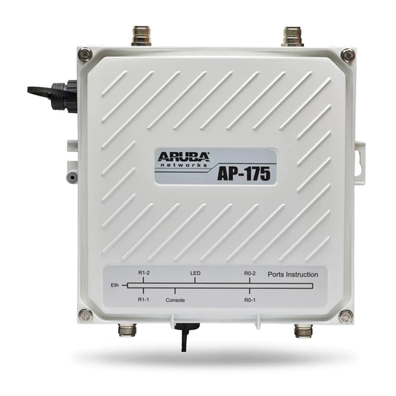
Aruba IAP-175 Outdoor Instant Access Point
Installation Guide
The Aruba IAP-175 is a resilient, environmentally hardened, outdoor rated, dual-radio, dual-band IEEE
802.11 a/b/g/n wireless access point. This outdoor access point is part of Aruba's comprehensive wireless
network solution. The IAP-175 can operate as an Aruba virtual controller or as a member of an Aruba
Instant wireless network.
The IAP-175 requires Aruba 3.0 Instant or later.
There are two versions of the IAP-175, which mainly differ in the way they receive power.
IAP-175P: PoE+ powered (802.3at)
IAP-175AC: AC powered (100 - 240 VAC)
The IAP-175AC can function as a Power Sourcing Equipment (PSE) device by providing power through its Ethernet
port in compliance with the IEEE 802.3af standard.
Guide Overview
"IAP-175 Hardware Overview" on page 3
models.
"Outdoor Planning and Deployment Considerations" on page 7
to consider when deploying an outdoor wireless network.
"Installing Antennas" on page 12
"Weatherproofing Connections" on page 12
connectors.
"Installing the IAP-175" on page 19
deployment of an IAP-175.
"Safety and Regulatory Compliance" on page 30
compliance information.
IAP-175 Operations
Wireless access point (IEEE 802.11 a/b/g/n)
Wireless air monitor (IEEE 802.11 a/b/g/n)
Enterprise mesh point
Enterprise mesh portal
Protocol-independent networking functionality
IAP-175P: IEEE 802.3at Power over Ethernet+ (PoE+) compatible
IAP-175AC: IEEE 802.3af Power Sourcing Equipment (PSE) device
0511096-02
| November 2012
provides a detailed hardware overview of the three IAP-175
describes how to installing antennas.
provides instructions on weatherproofing the AP's
describes the multi-step process for a successful installation and
provides an overview of safety and regulatory
provides key questions to ask and items
1
Advertisement
Table of Contents

Related Manuals for Aruba Networks IAP-175


Summary of Contents for Aruba Networks IAP-175
- Page 1 The Aruba IAP-175 is a resilient, environmentally hardened, outdoor rated, dual-radio, dual-band IEEE 802.11 a/b/g/n wireless access point. This outdoor access point is part of Aruba’s comprehensive wireless network solution. The IAP-175 can operate as an Aruba virtual controller or as a member of an Aruba Instant wireless network.
-
Page 2: Package Contents
Inform your supplier if there are any incorrect, missing, or damaged parts. If possible, retain the carton, including the original packing materials. Use these materials to repack and return the unit to the supplier if needed. Aruba IAP-175 Outdoor Instant Access Point | Installation Guide... -
Page 3: Antenna Interface
(2.4 or 5 GHz) and the desired coverage pattern. The IAP-175 is equipped with four, female N-type antenna interfaces; two on the top of the AP and two on the bottom. The interfaces are grouped into diversity pairs, one pair is marked R0 (Radio 0) and the other pair marked as R1 (Radio 1). - Page 4 Always remember to protect your IAP-175 by installing grounding lines. The ground connection must be complete before connecting power to the IAP-175 enclosure. Ensure that the resistance is less than 5 ohm between the ground termination point and the grounding tier.
- Page 5 Each bar represents a progressive Bars (Blue) increase in signal strength, with 4 bars representing maximum signal strength (100%). 25/50/75/100% Minimum data rate: One lit LEDs Maximum data rate: Four lit LEDs Aruba IAP-175 Outdoor Instant Access Point | Installation Guide...
- Page 6 IAP-175AC LED Status Indicators The IAP-175 include visual indicators for power, link, heat and radio status. Additionally, each radio has a four-LED array that indicates received signal strength (RSSI). The RSSI LED indicators represent varying degrees in the RSSI level. The absence of a signal is indicated by no LED response, and full signal strength is indicated when all four LEDs are active and lit.
-
Page 7: Outdoor Planning And Deployment Considerations
Client can be critical to success. To plan for these differences in elevation, it is important to understand the 3D coverage pattern provided by the antennas that will be deployed in the environment. Aruba IAP-175 Outdoor Instant Access Point | Installation Guide... -
Page 8: Identifying Known Rf Absorbers/Reflectors/Interferences Sources
If there are obstacles in the radio path, there may still be a radio link but the quality and strength of the signal will be affected. Calculating the maximum clearance from objects on a path is important as it directly Aruba IAP-175 Outdoor Instant Access Point | Installation Guide... -
Page 9: Antenna Height
To avoid any obstruction along the path, the height of the object must be added to the minimum clearance required for a clear radio line of sight. Consider the following simple example, illustrated in Figure Aruba IAP-175 Outdoor Instant Access Point | Installation Guide... -
Page 10: Antenna Position And Orientation
802.11a/ b/g channel frequencies. Always use a channel frequency that is furthest away from another signal. Aruba IAP-175 Outdoor Instant Access Point | Installation Guide... -
Page 11: Weather Conditions
It is important that the wireless bridge or mesh link, cables, and any supporting structures are properly grounded. Each IAP-175 access point includes a grounding screw for attaching a ground wire. Be sure that grounding is available and that it meets local and national electrical codes. Ground the access point first using the external ground stud on the unit before making any other connection. -
Page 12: Installing Antennas
7). The same materials are needed for weatherproofing both types of connections but the procedure is slightly different. For weatherproofing directly connected antennas, see "Weatherproofing Directly Connected Antennas" on page 14. For weatherproofing cable connections, see "Weatherproofing Cable Connections" on page 17. Aruba IAP-175 Outdoor Instant Access Point | Installation Guide... - Page 13 Figure 6 Directly Connected Antennas Weep holes Figure 7 Cable Connections Connectors on bottom of antenna N-type connector on an RF cable N-type connector on a pigtail Aruba IAP-175 Outdoor Instant Access Point | Installation Guide...
-
Page 14: Important Points To Remember
5. Repeat steps 3 and 4 until the wrapping extends all the way to the AP’s case. Figure 8 First Wrapping of Tape Pieces of tape as needed Wrap tape from just above knurled section to base of antenna mount Leave weep holes uncovered Aruba IAP-175 Outdoor Instant Access Point | Installation Guide... - Page 15 Figure 10 Butyl Rubber Wrap Wrap rubber around base Squeeze to of antenna bond rubber mount to itself Rubber will be wrapped with 4 layers of tape Aruba IAP-175 Outdoor Instant Access Point | Installation Guide...
- Page 16 Rubber will be wrapped with 4 layers of tape First and third layers wrap Second and final layers wrap top to bottom bottom to top 4. Repeat this process for all connectors. Aruba IAP-175 Outdoor Instant Access Point | Installation Guide...
-
Page 17: Weatherproofing Cable Connections
4. Repeat steps 3 and 4 until the wrapping extends all the way to the cable’s insulation. Figure 12 First Wrapping of Tape Wrap tape from antenna connector base to cable Pieces of tape as needed Aruba IAP-175 Outdoor Instant Access Point | Installation Guide... - Page 18 Stretch thinner & wider Figure 14 Butyl Rubber Wrap Squeeze to Rubber will bond rubber be wrapped to itself with 4 layers of tape Wrap rubber around connector and cable Aruba IAP-175 Outdoor Instant Access Point | Installation Guide...
-
Page 19: Selecting The Installation Site
4. Repeat this process for all connectors. Installing the IAP-175 The IAP-175 can be installed on a wall or attached to a pole. The following section describes how to attach the necessary hardware to the AP and how to mount the AP in the selected location. - Page 20 Installing the IAP-175 on a Pole 1. Attach the IAP-175 on the mounting bracket using the two M6 x30 bolts (with flat and spring washers) on each side of the mounting bracket.
- Page 21 Figure 17 Attaching the mounting bracket to the pole Installing the IAP-175 on a Wall 1. Begin by marking the screw points on the wall in the location you have selected. a. Put the mounting bracket on the installation position against the wall.
- Page 22 Adjust the position of the mounting bracket and tighten the expansion screws. 5. Attach the IAP-175 to the mounting bracket by inserting the two M6 x30 bolts (with flat and spring washers) through the installation holes, and tighten the bolts.
- Page 23 2. Fasten the copper lug to the grounding hole on the IAP-175 with the M4 x12 bolt and external-tooth washer. Aruba IAP-175 Outdoor Instant Access Point...
- Page 24 9. Slide the sealing nut over the narrow end of the weatherproof connector socket and hand tighten it. 10. Insert the ethernet cable connector into the Ethernet interface and hand-tighten the locknut. 11. Water-proof the Ethernet cable connection with electrical tape and butyl rubber. Aruba IAP-175 Outdoor Instant Access Point | Installation Guide...
- Page 25 13. Thread the sealing nut onto the sealing bolt. 14. Insert the Ethernet cable connector into the Ethernet interface and hand-tighten the locknut. 15. Water-proof the Ethernet cable connection with electrical tape and butyl rubber. Aruba IAP-175 Outdoor Instant Access Point | Installation Guide...
- Page 26 The required specifications for third party AC power cable used with the CKIT solution are as follows: 250V/1A minimum voltage/current rating 6-12mm diameter rated for outdoor use and UV exposure Figure 24 AC Power Connector PIN OUT on the AP-175AC Aruba IAP-175 Outdoor Instant Access Point | Installation Guide...
- Page 27 Attaching the Solar Shield to the IAP-175 Attach the solar shield to the IAP-175 by using the four M4 x16 (with flat and spring washers). Figure 25 Attaching the Solar Shield to the AP Aruba IAP-175 Outdoor Instant Access Point...
-
Page 28: Product Specifications
1 x 10/100/1000BASE-T Ethernet (RJ-45), auto-sensing link speed and MDI/MDX Power: 1 x AC power connector (in IAP-175AC model only) Antenna: 4 x N-Type female antenna interfaces Other: Aruba IAP-175 Outdoor Instant Access Point | Installation Guide... -
Page 29: Wireless Lan
802.11a/g: 6, 9, 12, 18, 24, 36, 48, 54 802.11n: MCS0 - MCS15 (6.5 Mbps to 300 Mbps) 802.11n high-throughput (HT) support: HT 20/40 802.11n packet aggregation: A-MPDU, A-MSDU Aruba IAP-175 Outdoor Instant Access Point | Installation Guide... -
Page 30: Safety And Regulatory Compliance
Safety and Regulatory Compliance Aruba Networks provides a multi-language document that contains country-specific restrictions and additional safety and regulatory information for all Aruba access points. This document can be viewed or downloaded from the following location: www.arubanetworks.com/safety_addendum RF Radiation Exposure Statement: This equipment complies with FCC RF radiation exposure limits. This equipment should be installed and operated with a minimum distance of 13.78 inches (35 cm) between the radiator... -
Page 31: Proper Disposal Of Aruba Equipment
Products and packaging will be marked with the “RoHS” label shown at the left indicating conformance to this Directive. China RoHS Aruba products also comply with China environmental declaration requirements and are labeled with the “EFUP 25” label shown at the left. Aruba IAP-175 Outdoor Instant Access Point | Installation Guide... - Page 32 Cet équipement respecte les limites établies par IC en matière d'exposition aux rayonnements, et doit être installé et utilisé en respectant une distance minimale de 20 cm entre l'élément rayonnant et votre corps. REGISTERED No: ER0055290/11 200202320G DEALER No: DA0039425/10 Aruba IAP-175 Outdoor Instant Access Point | Installation Guide...
- Page 33 This page is intentionally left blank. Aruba IAP-175 Outdoor Instant Access Point | Installation Guide...
- Page 34 This page is intentionally left blank. Aruba IAP-175 Outdoor Instant Access Point | Installation Guide...
- Page 35 This page is intentionally left blank. Aruba IAP-175 Outdoor Instant Access Point | Installation Guide...
-
Page 36: Contacting Aruba Networks
The use of Aruba Networks, Inc. switching platforms and software, by all individuals or corporations, to terminate other vendors' VPN client devices constitutes complete acceptance of liability by that individual or corporation for this action and indemnifies, in full, Aruba Networks, Inc. from any and all legal actions that might be taken against it www.arubanetworks.com with respect to infringement of copyright on behalf of those vendors.
Need help?
Do you have a question about the IAP-175 and is the answer not in the manual?
Questions and answers