Table of Contents
Advertisement
Quick Links
PROFESSIONAL MEDICAL PRODUCTS
CAPNO CUBE CAPNOGRAPH
User manual
CAPNO-T
Beijing Kingst Commercial & Trade Co., Ltd.
6th Floor, 2-7, Road Beibinhe in Xibianmen,
100045 Beijing, China
MADE IN CHINA
SUNGO Europe B.V.
Olympisch Stadion 24, 1076DE Amsterdam, Netherlands
Imported by: Gima S.p.A.
Via Marconi, 1 - 20060 Gessate (MI) Italy
gima@gimaitaly.com - export@gimaitaly.com
www.gimaitaly.com
(GIMA 33831)
IP33
0482
Advertisement
Table of Contents

Related Manuals for Gima CAPNO-T


Summary of Contents for Gima CAPNO-T
- Page 1 Beijing Kingst Commercial & Trade Co., Ltd. 6th Floor, 2-7, Road Beibinhe in Xibianmen, 100045 Beijing, China MADE IN CHINA SUNGO Europe B.V. Olympisch Stadion 24, 1076DE Amsterdam, Netherlands Imported by: Gima S.p.A. Via Marconi, 1 - 20060 Gessate (MI) Italy gima@gimaitaly.com - export@gimaitaly.com www.gimaitaly.com...
- Page 2 State Technological Supervision Bureau of China. It complies with both international and enterprise standards and is also approved by State Technological Supervision Bureau. The Manual is written for the current Capno-T Capnograph. The Manual describes, in accordance with the Capnograph’s features and requirements, main structure, functions, specifications, correct methods for transportation, installation, usage, operation, repair, maintenance and storage, etc.
- Page 3 ENGLISH Notice Welcome to use the Capnograph This manual includes the materials and copyright reserved. It is not allowed to copy, reduplicate or translate into other languages without our written permission. Please to read this manual carefully and then to operate by the instruction of this manual.
-
Page 4: Table Of Contents
ENGLISH CONTENTS Chapter 1 Preface ..................6 1.1 Brief ......................6 1.2 Warranty and Maintenance ..............6 1.3 Safety Requirements ................6 Chapter 2 - Technical specifications and characteristics ......10 Chapter 3 - Introduction of Monitor ............13 Chapter 4 - Patient connection ..............14 4.1 CO2 measurement ................14 4.2 Respiration rate measurement ............15 4.3 The sensor's zero ................16 4.4 Notice ....................16... - Page 5 ENGLISH Chapter 7 Trouble Shooting Analysis ............26 Appendix 1. Explanations of Terms in this Manual ........27 Appendix 2. ENGINEER MENU: Changing compensation of balance gas ....................28 Appendix 3. Guidance and manufacturer’s declaration- Electromagnetic compatibility ....................30...
-
Page 6: Chapter 1 Preface
ENGLISH Chapter 1 - Preface 1.1 Brief The purpose of this manual is to provide the User with a brief understanding of the characteristics, functions and operation of the monitor thereby preventing incorrect operation and user error. This device can monitor two physiological parameters for the patient at the same time: End tidal CO2 concentration (EtCO2), Respiration Rate (RR). - Page 7 ENGLISH Warning: Indicating the possible injury on patient or operator. General • Warning: To ensure accurate performance and prevent device failure, do preventive maintenance inspection (including performance and safety check) each 6 or 12 months to verify that the monitor operate functionally in good condition as ensuring patient and medical personnel safety.
- Page 8 ENGLISH symptoms. • Warning: Biocompatibility tests have been performed on all the applied parts, some exceptional allergic patients may still have anaphylaxis. Do not apply to those who have anaphylaxis. • Warning: do not modify this equipment without authorization from the manufacturer.
- Page 9 ENGLISH Fire Hazard • Warning: The monitor is not suitable for use in the presence of flammable anesthetic mixture with air, oxygen or nitrous oxide. Electrical • Warning: To protect against electric shock hazard, the monitor’s cover is to be removed only by qualified service personnel.
-
Page 10: Chapter 2 - Technical Specifications And Characteristics
ENGLISH Chapter 2 - Technical specifications and characteristics EtCO2 Method: Creative proprietary non-dispersive InfraRed Spectroscopy Range: 0 – 150mmHg or 0 – 20kPa or 0 – 20% (v/v) Accuracy: ±2mmHg for EtCO2 range 0 - 40mmHg ±5% for EtCO2 range from 41 - 70mmHg ±8% for EtCO2 range from 71 - 100mmHg Over 100mmHg ±10% Note 1: The accuracy of CO2 concentration measurement is influenced by any... - Page 11 ENGLISH in the gas loop is evacuated and its concentration measured is decreased and reaches zero, when exhaling, CO2 enters the breathing loop and its concentration rises rapidly and is kept at a certain platform, at the end tidal breathing it reaches maximum.
- Page 12 ENGLISH Atmospheric pressure: 86-106 kPa Storage Conditions Temperature: -20 to +55oC Relative Humidity:<93% (non-condensing) = < 29.45 hPa Atmospheric pressure: 50 - 120 kPa Dimensions of Monitor Size: 38 x 42 x 44mm (W x H x D) Weight: 80g (including lithium battery and adult airway adapter) Warranty &...
-
Page 13: Chapter 3 - Introduction Of Monitor
ENGLISH Chapter 3 - Introduction of Monitor Figure 1 (1) Screen: Displays waves, menu, alarm and all measuring parameters. (2) S button: Press this button to move the cursor when menu is activated. (3) +/ Multifunction button a) When menu is activated, to press this button as confirmation button or increase (+) button. -
Page 14: Chapter 4 - Patient Connection
ENGLISH Figure 2 (5): Multifunction button a) Power switch, to press this button for two seconds to turn on or turn off power. b) To press this button and quickly be off the button to enter or quit the menu. (6) Light indicator: Flickering green light indicates power adapter is connected and green light indicates the device begins to work. -
Page 15: Respiration Rate Measurement
ENGLISH Theory introduction The principle is based on the fact that CO2 molecules absorb infrared light energy of specific wavelengths, with the amount of energy absorbed being directly related to the CO2 concentration. When an IR light beam is passed through a gas sample containing CO2, the electronic signal from a infrared sensor (which measures the remaining light energy), can be obtained. -
Page 16: The Sensor's Zero
ENGLISH 4.3 The sensor's zero 1). Zero The vapour-prevent window of the airway adapter has a certain attenuation to infrared signal but due to individual diversity, its attenuation is different. So the sensor needs to be zeroed when changing new adapter. In addition, the sensor and in fared source have a certain of drifting, the sensor need to be zeroed after long usage, if the data is not correct, sensor also needs zero. -
Page 17: Chapter 5 Screen Display And Operation
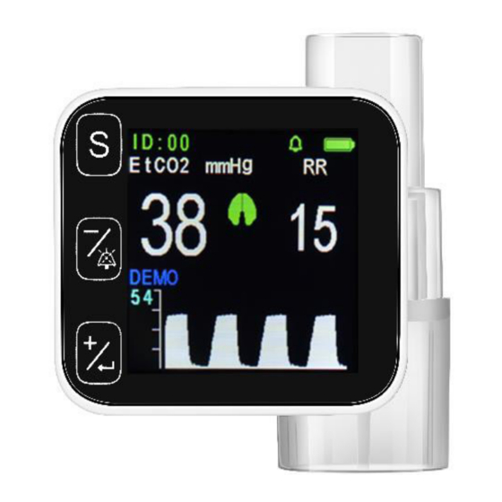
ENGLISH Chapter 5 - Screen display and Operation 5.1 Screen main display menu Figure 4 1. The first line of data shows time (hour, minute)/patient ID, the memory area full indicator ) , silence ( ) or non silence (), bluetooth symbol ( ) and battery indicator Attention: a) When the memory full indicator is displayed, further patient data cannot be... - Page 18 ENGLISH Alarm setting: The alarm settings of the system will not change after shutting down the power of capnograph. Alarming level: There are two types of alarming: physiological alarm and technical alarm. Physiological alarm refers to the alarm causing by physiological change of patient, patient’s life may in danger.
- Page 19 ENGLISH Alarm sound: Alarm sounds as following description. Time interval cannot be changed. Level of alarm Sound Sound pressure Beep-Beep Beep”, triggered Medium priority alarm 45-70dB each 8 seconds Alarm light: Alarm light looks like following description Level of alarm Light Parameter indicator turn yellow, blinking with Intermediat alarm...
-
Page 20: The Main Menu
ENGLISH 5.2 The Main Menu Figure 5 In the main display screen, to press the button to enter the setup menu, see the picture above. In this menu, to press button S to move the cursor to choose item. In this menu, to press button +/ to enter the next submenu, to press again to go back to the main display screen. - Page 21 ENGLISH In this menu, to press button S to move the cursor to choose item, to press button +/ or button to change data highlighted by the cursor. Some items in this menu, if there are some actions not for changing data but just for direct operations such as LOAD_DEFAULTS or EXIT, then to press button +/ to execute.
-
Page 22: Time Set Menu
ENGLISH 5.4 TIME SET Menu Figure 7 In this menu to press button S to move the cursor to choose item, to press button or button to change data highlighted by the cursor. Attention: Any time adjustment will delete any stored trend data, so please take care before making this adjustment. -
Page 23: New Patient Menu
ENGLISH 5.5 NEW PATIENT Menu Figure 9 In this menu to press button S to move the cursor to choose item, to press button or button o change data highlighted by the cursor. In this menu, press button, to exit this menu and enter the main display screen. -
Page 24: Maintenance
ENGLISH unit is > 6 Hours. Charge time is approx. 4 Hours. Battery replacement method: Note that the operation must be done with the DC Charger disconnected ensuring that the operator’s safety is not compromised. Press down and slide off to remove the battery cover, then carefully disconnect and remove the battery. - Page 25 ENGLISH a) The monitor's window: Use cotton swab or cloth strip wetted by clean water to graze and remove blot and naturally air dried. Be sure it is dry before usage. b) Cleaning and disinfecting of adapter: Disinfection: ● For single use airway adapter (A3,A3N): Reuse of the single use Adapter can cause cross infection.
-
Page 26: Chapter 7 Trouble Shooting Analysis
ENGLISH Chapter 7 - Trouble Shooting Analysis Simple analysis of problems Phenomena Causes Solution The values of 1. Leakageofgas 1. Check and CO2 is lower loop replacegasloopand adapter. 2. Needzero 2. Sensorzeros. 3.Theiwindowof adapterhas vapor 3. Wait for the (lowtemperature) temperaturerising 4. -
Page 27: Appendix 1. Explanations Of Terms In This Manual
ENGLISH Flashing red 1. Battery lack 1. To connect AC/DC colour of power. power adapter. closed down automatically Still flashing red AC/DC power 1. To check the AC/DC colour after adapter working adapter and cable. the power is abnormally. supplied and AC indicator no light. -
Page 28: Appendix 2. Engineer Menu: Changing Compensation Of Balance Gas
ENGLISH Offset Calibration Nitrous oxide HELIUM Helium gas O2 CONCENT O2 concentration compensation ANAESTHETIC Anaesthetic gas ZERO GAS Base point or Zero point Temperature and deep lung air pressure BTPS compensation CALIBRATE Calibration CANCEL: Cancellation Appendix 2. ENGINEER MENU: Changing compensation of balance gas Attention: Only the trained personnel may carry out the following the procedure. - Page 29 ENGLISH In this menu to press button S to move the cursor to choose item, to press button or button to change data highlighted by the cursor. In this menu, press button, to exit this menu and enter the main display screen.
-
Page 30: Appendix 3. Guidance And Manufacturer's Declaration-Electromagnetic Compatibility
ENGLISH Appendix 3. Guidance and manufacturer’s declaration- Electromagnetic compatibility Table 1 - Guidance and manufacturer’s declaration- electromagnetic emission-for all EQUIPMENTAND SYSTEMS This device is intended for use in the electromagnetic environment specified below. The customer or the user of the equipment or system should assure that it is used in such an environment. - Page 31 ENGLISH Table 2 - Guidance and manufacturer’s declaration- electromagnetic immu- nity for all EQUIPMENTAND SYSTEMS This device is intended for use in the electromagnetic environment specified below. The customer or the user of the equipment or system should assure that it is used in such an environment.
- Page 32 ENGLISH Mains power quality 0% UT (100% 0% UT (100% should be that of a dip in UT) for 0,5 dip in UT) for typical commercial or cycle 0,5 cycle Voltage hospital environment. 0% UT (100% 0% UT (100 % dips, short If the user of the dip in UT) for 1...
- Page 33 ENGLISH IMMUNITY IEC 60601 Complia Electromagnetic test test level nce level environment - guidance RF condotta 3 Vrms da 150 3 Vrms Portable and mobile RF kHz a 80MHz da 150 kHz communications equipment RF IEC (6V in ISM e a 80MHz (6V should be used no closer bande radio...
- Page 34 ENGLISH Table 4 Recommended separation distances Recommended separation distances between portable and mobile RF com- munications equipment and the equipment or system for EQUIPMENT and SYSTEM that are not LIFE- SUPPORTING Recommended separation distances between Portable and mobile RF communications equipment and the device This device is intended for use in an electromagnetic environment in which radiated RF disturbances are controlled.
- Page 35 Disposal: The product must not be disposed of along with other domestic waste. The users must dispose of this equipment by bringing it to a specific recycling point for electric and electronic equipment GIMA WARRANTY TERMS The Gima 12-month standard B2B warranty applies...
Need help?
Do you have a question about the CAPNO-T and is the answer not in the manual?
Questions and answers