Advertisement
Table of Contents
- 1 Table of Contents
- 2 Warning Decal Placement
- 3 Important Precautions
- 4 Before You Begin
- 5 Part Identification Chart
- 6 Assembly
- 7 How to Use the Studio Cycle
- 8 How to Use the Console
- 9 Fcc Information
- 10 Maintenance and Troubleshooting
- 11 Exercise Guidelines
- 12 Part List
- 13 Exploded Drawing
- 14 Ordering Replacement Parts
- 15 Limited Warranty
- Download this manual
nordictrack.com
Model No. NTEX02422.5
Serial No.
Write the serial number in the space
above for reference.
Serial Number
REGISTER YOUR
PRODUCT
To register your product and
activate your warranty today,
go to my.nordictrack.com.
MEMBER CARE
For service at any time, go to
support.nordictrack.com.
Or call 1-833-680-IFIT
(1-833-680-4348)
Mon.–Fri. 6 a.m.–6 p.m. MT
Sat. 8 a.m.–12 p.m. MT
Please do not contact the store.
CAUTION
Read all precautions and
instructions in this manual before
using this equipment. Keep this
manual for future reference.
Decal
USER'S MANUAL
Advertisement
Table of Contents

Related Manuals for iFIT NordicTrack S22i


Summary of Contents for iFIT NordicTrack S22i
- Page 1 To register your product and activate your warranty today, go to my.nordictrack.com. MEMBER CARE For service at any time, go to support.nordictrack.com. Or call 1-833-680-IFIT (1-833-680-4348) Mon.–Fri. 6 a.m.–6 p.m. MT Sat. 8 a.m.–12 p.m. MT Please do not contact the store. CAUTION...
-
Page 2: Table Of Contents
Apply the decal in the location shown. Note: The decal(s) may not be shown at actual size. NORDICTRACK and IFIT are registered trademarks of iFIT Inc. The Bluetooth ® word mark and logos are regis- tered trademarks of Bluetooth SIG, Inc. and are used under license. Google Maps is a trademark of Google LLC. -
Page 3: Important Precautions
To reduce the risk of serious injury, read all important precautions and instructions in this manual and all warnings on your studio cycle before using your studio cycle. iFIT assumes no responsibility for personal injury or property damage sustained by or through the use of this product. - Page 4 STANDARD SERVICE PLANS...
-
Page 5: Before You Begin
BEFORE YOU BEGIN Congratulations for selecting the revolutionary For your benefit, read this manual carefully before NORDICTRACK ® COMMERCIAL S22I STUDIO you use the studio cycle. If you have questions after CYCLE. The COMMERCIAL S22I STUDIO CYCLE is reading this manual, please see the front cover of this unlike any ordinary exercise bike. -
Page 6: Part Identification Chart
PART IDENTIFICATION CHART Use the drawings below to identify the small parts needed for assembly. The number in parentheses below each drawing is the key number of the part, from the PART LIST near the end of this manual. The number following the key number is the quantity needed for assembly. -
Page 7: Assembly
ASSEMBLY 1. To use the assembly steps in this manual, first see the helpful tips below. • Assembly requires two persons. • In addition to the included tool(s), assembly requires the following tool(s): • Place all parts in a cleared area and remove the one Phillips screwdriver packing materials. - Page 8 2. See the inset drawing. Orient the Handlebar Post (7) so that the lower slot (A) is on the side shown. Next, loosen the indicated Post Knob (100) and insert the Handlebar Post (7) into the Frame (1) until the lower end of the Handlebar Post is below the Frame.
- Page 9 4. Remove the Mount Cover (153) from the Console Support (8), if necessary. Then, pull the wires (D) out of the Console Support. Make sure that the wires are behind the Console Bracket (11). Then, press the Mount Cover (153) into place on the Console Support (8).
- Page 10 6. Look under the Console Support (8) and identify the Upper Wire (123), which has a larger con- nector than the Extension Wire (124). Connect the Upper Wire (123) to the Lower Wire (122) extending from the Handlebar Post (7). Tip: The wire connectors should slide together easily and snap into place with an audible click.
- Page 11 8. Orient the Lower Console Cover (154) as shown and press it onto the back of the Console (10). Position the wires (not shown) in the indi- cated notch (G). Tip: Avoid pinching the wires. Orient the Upper Console Cover (155) as shown and press it onto the back of the Console (10).
- Page 12 10. Position the wires (D, E) so that they fit neatly in the underside of the Hand Weight Tray (38). Orient the Tray Cover (106) so that the curved opening (J) is in the location shown. Then, align the Tray Cover with the Hand Weight Tray (38). D, E Tip: Avoid pinching the wires (D, E).
- Page 13 12. Set the two Hand Weights (14) in the Hand Weight Tray (38). IMPORTANT: Make sure not to hit the Console (10) with the Hand Weights (14) when you set the Hand Weights in the Hand Weight Tray (38) after each use. 13.
-
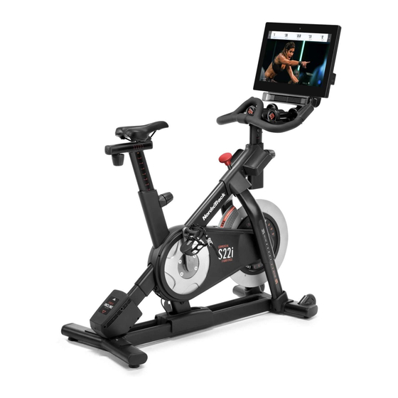
Page 14: How To Use The Studio Cycle
Interactive Wireless Touchscreen Console let that is properly installed in accordance with all local codes and ordinances. The wireless touchscreen console works with iFIT to provide an interactive and immersive in-home studio experience that allows you to participate virtually in group studio classes led by personal trainers and to experience workouts around the world. - Page 15 HOW TO ADJUST THE GEOMETRY OF THE To adjust the saddle STUDIO CYCLE post, loosen the post knob (D), The studio cycle can be adjusted to match the geom- move the saddle etry of your road bike to promote correct form and to post upward or ensure proper training of the muscles.
- Page 16 HOW TO LEVEL THE STUDIO CYCLE The spring tension affects how easy or If the studio cycle difficult it is to clip in rocks slightly on and unclip from the your floor during pedals. To adjust use, turn one or the spring tension both of the leveling of a pedal (L), use...
-
Page 17: How To Use The Console
The console features wireless technology that enables rate using a compatible heart rate monitor. the console to connect to iFIT. With iFIT, you can access a large and varied workout library, create your To turn on and turn off the console, see page 18. - Page 18 HOW TO TURN ON THE CONSOLE HOW TO USE THE TOUCH SCREEN The included power adapter must be used to operate The console features a tablet with a full-color touch the studio cycle. See HOW TO PLUG IN THE POWER screen.
- Page 19 1. Connect to your wireless network. Also, some settings and features described in this manual may no longer be enabled. To use iFIT workouts and to use several other features of the console, the console must be con- 5. Calibrate the incline system.
- Page 20 HOW TO USE THE MANUAL MODE Note: To view the resistance or incline sliders on the screen, touch the screen in any open space 1. Touch the screen or press any button on the and then touch the controls options to enable this console to turn on the console.
- Page 21 5. Wear a compatible heart rate monitor and THE OPTIONAL HEART RATE MONITOR measure your heart rate if desired. Whether your You can wear a compatible heart rate monitor (not goal is to included) to measure your heart rate. The console burn fat or to is compatible with all Bluetooth ®...
- Page 22 Follow Trainer. ing the favorites button (heart symbol). You must be logged into your iFIT account to save a featured If the smart adjust feature is enabled, the con- workout (see step 3 on page 25).
- Page 23 If desired, you can select options such as adding the workout to your sched- ule (see HOW TO USE AN IFIT WORKOUT on page 25) or adding the workout to your favor- ites list. Then, touch Finish to return to the home...
- Page 24 HOW TO CREATE A DRAW-YOUR-OWN-MAP If you make a mistake, touch Undo in the map WORKOUT options. 1. Touch the screen or press any button on the The screen will display the elevation and distance console to turn on the console. statistics for your workout.
- Page 25 (see step 6). button (three horizontal lines symbol) on the screen and then touch Log in to log in to your iFIT account. 5. Schedule an iFIT workout on the calendar if Follow the prompts on the screen to enter your desired.
- Page 26 6. Create a list of favorite iFIT workouts if desired. When your headphones and the console pair successfully, the audio from the console will play To mark an iFIT workout as a favorite, simply view through your headphones. the overview or workout summary of the desired iFIT workout and touch the favorites button (heart 9.
- Page 27 HOW TO CHANGE CONSOLE SETTINGS 3. Customize workout settings. IMPORTANT: Firmware updates are always To customize workout settings and enable workout designed to improve your exercise experience. As a features, touch In Workout, and then touch the result, new settings and features may not be described desired settings.
- Page 28 HOW TO CONNECT TO A WIRELESS NETWORK Follow the prompts on the screen to enter your To use iFIT workouts and to use several other features password and connect to the selected wireless of the console, the console must be connected to a network.
-
Page 29: Fcc Information
FCC INFORMATION This equipment has been tested and found to comply with the limits for a Class B digital device, pursuant to Part 15 of the FCC Rules. These limits are designed to provide reasonable protection against harmful interference in a residential installation. This equipment generates, uses, and can radiate radio frequency energy and, if not installed and used in accordance with the instructions, may cause harmful interference to radio communications. -
Page 30: Maintenance And Troubleshooting
If you are having problems connecting the console to a wireless network or if you are having problems Regular maintenance is important for optimal with your iFIT account or iFIT workouts, go to performance and to reduce wear. Inspect and properly support.iFIT.com. - Page 31 HOW TO ADJUST THE CONSOLE PIVOT AND TILT INCLINE SYSTEM TROUBLESHOOTING If the console feels too loose or does not stay in place If the frame does not move to the correct incline level, when it is moved from side to side, first remove the see HOW TO CHANGE CONSOLE SETTINGS on Mount Cover (153).
- Page 32 HOW TO ADJUST THE REED SWITCH If the console does not display correct feedback, the reed switch should be adjusted. To adjust the reed switch, first press the power switch and unplug the power adapter. Next, remove the three indicated M4 x 14mm Screws (17) from the Right and Left Shields (30, 32).
- Page 33 HOW TO ADJUST THE DRIVE BELT If you can feel the pedals slip while you are pedaling, even when the resistance is adjusted to the highest setting, the drive belt may need to be adjusted. To adjust the drive belt, first press the power switch and unplug the power adapter.
-
Page 34: Exercise Guidelines
EXERCISE GUIDELINES Aerobic Exercise—If your goal is to strengthen your WARNING: cardiovascular system, you must perform aerobic Before beginning this exercise, which is activity that requires large amounts or any exercise program, consult your physi- of oxygen for prolonged periods of time. For aerobic cian. -
Page 35: Part List
PART LIST Model No. NTEX02422.5 R1021A Key No. Qty. Description Key No. Qty. Description Frame Resistance Disc Base Lower Saddle Clamp Power Switch Upper Saddle Clamp Roller Axle Saddle M6 Shoulder Screw Anchored Zip Tie Inner Leg Sleeve Cleat Assembly Handlebar Post #8 x 1/2"... - Page 36 Key No. Qty. Description Key No. Qty. Description Carriage Knob Adjustment Block M6 x 20mm Machine Screw M4 x 10mm Blunt Screw M4 x 10mm Machine Screw M10 x 20mm Hex Screw Roller Plastic Spacer M10 Washer M10 Locknut Tray Cover Shoe Pin M4 x 15mm Machine Screw Pulley Magnet...
-
Page 37: Exploded Drawing
EXPLODED DRAWING A Model No. NTEX02422.5 R1021A 86 57... - Page 38 EXPLODED DRAWING B Model No. NTEX02422.5 R1021A...
- Page 39 EXPLODED DRAWING C Model No. NTEX02422.5 R1021A...
-
Page 40: Ordering Replacement Parts
This warranty extends only to the original purchaser (customer) and is not transferrable. iFIT’s obligation under this warranty is limited to repairing or replacing, at iFIT’s discretion, the product through one of its authorized service providers. All repairs for which warranty claims are made must be preauthorized by iFIT.
Need help?
Do you have a question about the NordicTrack S22i and is the answer not in the manual?
Questions and answers
Lost all power to the bike past the power adapter. What is the likely cause.
If the NordicTrack S22i bike loses all power beyond the power adapter, one possible cause is that the console may need to be reset. A reset involves unplugging the power adapter, pressing and holding the reset button inside the small reset opening, and then plugging the adapter back in while pressing the power switch. If the console still does not turn on, ensure the power adapter is fully plugged in.
This answer is automatically generated