Table of Contents
Advertisement
Quick Links
Advertisement
Table of Contents

Related Manuals for Pulsar PG3500MRCO


Summary of Contents for Pulsar PG3500MRCO
- Page 1 Model: PG3500MRCO Generator OPERATOR’S MANUAL support@pulsar-products.com...
-
Page 2: Table Of Contents
TABLE OF CONTENTS Introduction....................................3 Product Specifications..............................3 Parts Ordering / Customer Service..........................3 Safety Rules.....................................4 Safety Symbols................................4 Safety Instructions ..............................4 Features....................................7 Assembly....................................9 Unpacking ................................. ..9 Packing List .................................9 Attaching Wheels................................10 Adding Oil...................................11 Adding Fuel................................12 Connecting Generator to a Building Electrical System.....................12 Operation....................................13 Grounding the Generator ............................13 How to Start Engine..............................13... -
Page 3: Introduction
INTRODUCTION Thank you for purchasing this superior quality portable generator from Pulsar Products Inc. When operating and maintaining this product as instructed in this manual, your generator will give you many years of reliable service. Product Specifications: This generator is an engine-driven, revolving field, alternating current (AC) portable generator. It is designed to supply electrical power to operate tools, appliances, camping equipment, lighting, or serve as a backup power source during power outages. -
Page 4: Safety Rules
SAFETY RULES Safety Symbols Indicates a potentially hazardous WARNING! situation which could result in serious injury or death if not avoided. Indicates a potentially hazardous CAUTION! situation which could result in damage to equipment or property. Toxic Fumes Risk of fire Risk of explosion Risk of electric shock Hot surface... - Page 5 SAFETY RULES Never exceed generator’s wattage / amperage capacity. This could damage the generator WARNING! and / or connected electrical devices. Check operating voltage and frequency requirements of all electrical devices prior to plugging them into the generator. • Never start or stop engine with electrical devices plugged in to the receptacles. Failure to do WARNING! so could damage the generator and / or connected electrical devices.
- Page 6 Never transport or make adjust this unit while it is running. • Never insert objects through cooling slots. Never operate this unit if there are any broken or missing parts and only use Pulsar WARNING! replacement parts specifically designed for this unit.
-
Page 7: Features
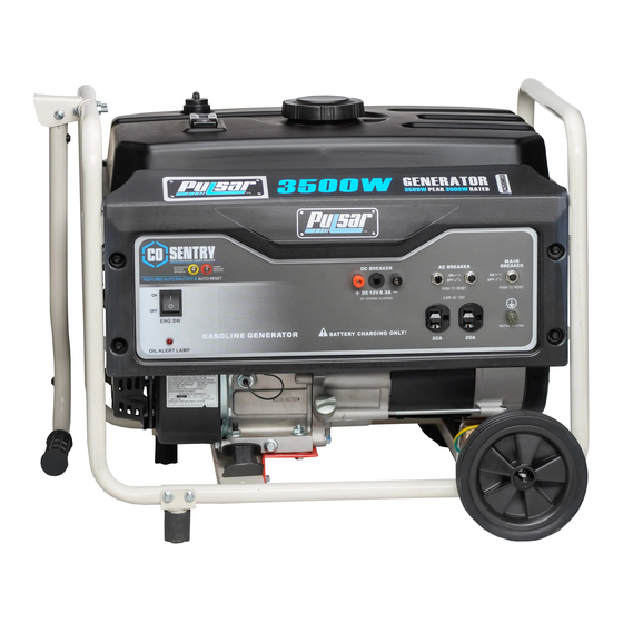
FEATURES A - ON/OFF Switch F -120V NEMA-5 Receptacle B - DC Circuit Breakers G -12V DC Output C - AC Circuit Breakers H - Low Oil Alert D - Main Circuit Protectors I - CO Sensor Light E - Ground Connection... - Page 8 FEATURES J - Tank Vapor Valve O - Handle P - Support Leg K - Choke Lever Q - Fuel Tank L - Fuel Valve (ON/OFF) R - No Flat Tires M - Recoil Starter Grip N - Air Filter Housing...
-
Page 9: Assembly
ASSEMBLY Unpacking 1. Place box on a level surface. 2. Remove all items from box except the generator. Make sure all items listed on the packing list are included and undamaged 3. Cut-down the sides of the box being careful to avoid touching the generator. 4. -
Page 10: Attaching Wheels
ASSEMBLY Attaching Handle (See fig 1) • Parts needed - 1 handle, 1 handle bracket , 4 screws and nuts. • Install handle bracket to generator frame. (fig. 1) • Attach handle to the bracket handle. Attaching Wheels (See fig 2) •... -
Page 11: Adding Oil
ASSEMBLY Adding / Checking Engine Oil (See fig 4) Place generator on a level surface. • Clean area around oil fill. • Remove oil fill cap and wipe dipstick clean. • Screw dipstick into filler neck. Remove dipstick and verify oil level is within safe operating range. •... -
Page 12: Adding Fuel
ASSEMBLY Adding Fuel (See fig 5) • Set generator outdoors in a well-ventilated area, away from structures and people. • Slowly remove fuel cap. • Insert a funnel into the fuel tank and carefully pour gasoline into the tank until fuel level reaches 1 ½ inches below the top of the neck. -
Page 13: Operation
OPERATION Grounding the Generator (See fig 6) ground grounding an earthen ground neutral Fig 6 WARNING! Generator must be properly grounded to prevent electrocution. • When operated as a portable generator, keep out of rain and away from standing water •... -
Page 14: How To Stop Engine
OPERATION CHOKE CHOKE LEVER Fig 7 Fig 8 WAIT 5sec CHOKE CHOKE LEVER Fig 10 Fig 9 Recoil Start How to Stop Engine (See fig 11-13) All electrical loads MUST be disconnected from the generator. Never start or stop the engine with electrical devices •... -
Page 15: Receptacles And Extension Cords
OPERATION Receptacles and Extension Cords Only use high quality, well-insulated, grounded extension cords in good condition with generator receptacles. Extension cords should have a minimum rating of 125 Volts AC, 20 Amps and should be kept as short as possible to minimize voltage drop. -
Page 16: Don't Overload Generator
OPERATION Extension Cord Selection Refer to the below table to ensure the extension cord used has the capacity to carry the required load. If the size of the cable is inadequate it can cause a voltage drop and heat buildup, which can damage the electrical device and cord. Load (Watts) Maximum Cord Length Current... -
Page 17: Wattage Reference Guide
OPERATION Operating voltage and frequency requirement of all electrical equipment should be checked prior to plugging them into this generator. Damage may result if the equipment is not designed to operate within a +/- 10% voltage variation, and +/- 3 Hz frequency variation from the generator name plate ratings. -
Page 18: Cold Weather Operation
OPERATION Power Management Start engine without anything connected to generator. • • When engine has stabilized, plug in and turn on first load. It is strongly recommended to plug in devices with the largest output first and the smallest output last to help prevent overloading the generator. •... -
Page 19: Maintenance
MAINTENANCE Regular maintenance will extend the life of this generator and improve its performance. The warranty does not cover items that result from operator negligence, misuse, or abuse. To receive full value from the warranty, operator must maintain the generator as instructed in this manual, including proper storage. Before inspecting or servicing this machine, make sure the engine is off and no parts are WARNING! moving. -
Page 20: Engine Maintenance
MAINTENANCE Changing Oil (See Fig 14) • Run the Generator until the Engine is warm, then shut OFF. • Place generator on a level surface. • Remove the crankcase dipstick. • Place an oil pan underneath the oil drain hole to collect used oil. •... - Page 21 Replacing Fuel Filter ( If Applicable) Occasionally the fuel filter may become clogged and need replacing. To purchase a replacement fuel filter contact PULSAR customer service or your local small engine repair shop. • Turn the fuel valve to the “OFF” position.
-
Page 22: How To Store
MAINTENANCE Draining the fuel tank • Turn the fuel valve to the OFF position. • Turn the engine OFF • Push the fuel valve knob through the valve holder bracket allowing you to access the petcock. • Remove the fuel line that leads from the carburetor to the petcock by squeezing the ends of the hose clamps and sliding the fuel line off. -
Page 23: Troubleshooting
TROUBLESHOOTING Problem Cause Solution Engine is running, but AC output is not 1. Open circuit breaker 1. Reset circuit breaker available 2. Poor connection 2. Check and repair 3. Defective cord set 3. Check and repair 4. Connected device is faulty 4. -
Page 24: Diagrams
DIAGRAMS... - Page 25 The YELLOW light will flash for at least five minutes after a fault. The generator can be re-started, but may continue to shutoff. A CO sensor fault can only be diagnosed and repaired by an authorized Pulsar service center.
Need help?
Do you have a question about the PG3500MRCO and is the answer not in the manual?
Questions and answers