Stryker Power-LOAD 6390 Maintenance Manual
Cot fastener system
Hide thumbs
Also See for Power-LOAD 6390:
- Operation & maintenance manual (193 pages) ,
- Maintenance manual (154 pages) ,
- Operation manual (66 pages)

Subscribe to Our Youtube Channel
Related Manuals for Stryker Power-LOAD 6390


Summary of Contents for Stryker Power-LOAD 6390
- Page 1 P P o o w w e e r r - - L L O O A A D D ® ® C C o o t t F F a a s s t t e e n n e e r r S S y y s s t t e e m m M M a a i i n n t t e e n n a a n n c c e e M M a a n n u u a a l l 6390 6390-309-002 Rev AB.0...
- Page 3 Caution Warning; crushing of hands Warning; non-ionizing radiation Catalogue number Lot (batch) code Serial number For US Patents see www.stryker.com/patents Manufacturer Date of manufacture Safe working load Dangerous voltage Medical Equipment Recognized by Underwriters Laboratories LLC With Respect to Electric Shock, Fire, and Mechanical Hazards only in accordance with ANSI/AAMI ES60601-1:2012 and CAN/CSA-C22.2 No.
- Page 4 In accordance with European Directive 2012/19/EU on Waste Electrical and Electronic Equipment (WEEE) as amended, this symbol indicates that the product should be collected separately for recycling. Do not dispose of as unsorted municipal waste. Contact local distributor for disposal information. Ensure infected equipment is decontaminated prior to recycling. The Rechargeable Battery Recycling Corporation (RBRC) is a non-profit, public service organization that promotes the recycling of portable rechargeable batteries.
- Page 5 Box manufacturer’s certificate - this packaging box has minimum edge crush test value of 82 lb/ Box manufacturer’s certificate - this packaging box has minimum edge crush test value of 51 lb/ 6390-309-002 Rev AB.0...
- Page 7 T T a a b b l l e e o o f f C C o o n n t t e e n n t t s s Warning/Caution/Note Definition ..........................4 Summary of safety precautions ..........................4 Pinch points ...............................5 Introduction ................................6 Product description ..............................6...
- Page 8 Cot does not jog down once in the transport position....................24 Trolley manual release button does not lower the lifting arms ...................25 Trolley manual release button lowers the lifting arms, but not smoothly ..............25 Trolley error LED indicates an error (solid amber) ....................25 Trolley control panel does not move the lifting arms ....................25 Trolley stops part way while rolling to the transport position ..................25 Trolley is in the transport position with a cot and the trolley LEDs are not illuminated green.........26...
- Page 9 Trolley manual release assembly ......................... 106 Trolley arm assembly ............................108 Arm, left ................................. 109 Arm, right ................................110 Trolley actuator assembly - 6390-001-028 ......................111 Floor plate, install components ..........................112 Wheel guide, optional ............................113 Wheel guide assembly, optional - 6390-001-017 ....................
- Page 10 • The use of accessories, transducers, and cables, other than those specified, with the exception of transducers and cables that are sold by Stryker as replacement parts for internal components, may result in increased emissions or decreased immunity of the P P o o w w e e r r - - L L O O A A D D system.
- Page 11 • This equipment has been tested and found to comply with the limits for a Class A digital device, pursuant to part 15 of the FCC Rules. These limits are designed to provide reasonable protection against harmful interference when the equipment is operated in a commercial environment.
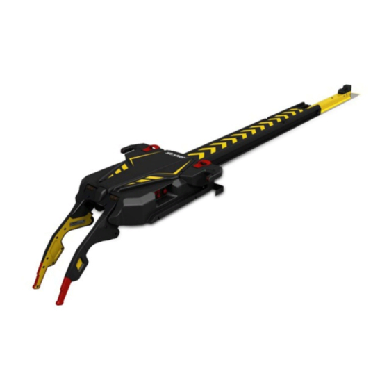
- Page 12 P P r r o o d d u u c c t t d d e e s s c c r r i i p p t t i i o o n n The Stryker Model 6390 P P o o w w e e r r - - L L O O A A D D ® power-loading cot fastener system is designed to lift, lower, or steer compatible ambulance cots into and out of an emergency ground transport vehicle.
-
Page 13: Electrical Requirements
C C o o n n t t r r a a i i n n d d i i c c a a t t i i o o n n s s None known. E E x x p p e e c c t t e e d d s s e e r r v v i i c c e e l l i i f f e e P P o o w w e e r r - - L L O O A A D D has a seven year expected service life under normal use conditions and with appropriate periodic maintenance. -
Page 14: Relative Humidity
The yellow and black color scheme is a proprietary trademark of Stryker Corporation. Hereby, Stryker declares that the radio equipment type short range device is in compliance with Directive 2014/53/EU. The full text of the EU declaration of conformity is available at the following internet address: http://techweb.med.strykercorp. - Page 15 • Do not use portable RF communications equipment (including peripherals such as antenna cables and external antennas) no closer than 30 cm (12 in.) to any part of the P P o o w w e e r r - - L L O O A A D D system, including cables specified by the manufacturer.
-
Page 16: Anchor Assembly
Competent authority of the European Member State where the user and/or patient is established. To view your operations or maintenance manual online, see https://techweb.stryker.com/. Have the serial number (A) of your Stryker product available when calling Stryker Customer Service or Technical Support. Include the serial number in all written communication. - Page 17 Individual usage If you are not sure how or when to perform these checks, contact your Stryker Service Technician. When you perform P P o o w w e e r r - - L L O O A A D D preventive maintenance checks, you must perform a preventive maintenance check on its corresponding P P o o w w e e r r - - L L O O A A D D compatible cot and the optional wheel guide assembly (if applicable) to confirm operability of the entire system.
- Page 18 E E v v e e r r y y t t w w e e l l v v e e m m o o n n t t h h s s C C h h e e c c k k R R o o u u t t i i n n e e Battery Replace if lifting is sluggish...
- Page 19 T T r r a a n n s s f f e e r r l l o o c c k k b b e e a a r r i i n n g g p p a a r r t t r r e e p p l l a a c c e e m m e e n n t t s s c c h h e e d d u u l l e e You must replace the transfer lock bearing parts every 3,653 calls.
- Page 20 T T r r a a i i n n i i n n g g r r e e c c o o r r d d T T r r a a i i n n i i n n g g d d a a t t e e T T r r a a i i n n e e e e n n a a m m e e B B a a s s i i c c t t r r a a i i n n i i n n g g R R e e f f r r e e s s h h e e r r u u p p d d a a t t e e...
- Page 21 T T r r o o u u b b l l e e s s h h o o o o t t i i n n g g T T r r a a n n s s f f e e r r / / c c o o t t d d o o e e s s n n o o t t m m o o v v e e o o u u t t o o f f t t h h e e t t r r a a n n s s p p o o r r t t p p o o s s i i t t i i o o n n Transfer/cot does not move out of the transport position when you press the release lever at the foot end of the anchor.
- Page 22 3. If rolling is still difficult, check to see if the transfer extrusion is worn around the channels. If so, replace the V-guide rollers on the anchor. T T r r o o l l l l e e y y r r o o l l l l s s p p a a r r t t o o f f t t h h e e w w a a y y a a n n d d s s t t o o p p s s 1.
- Page 23 8. Check the connection of the trolley main cable (6390-001-391) to the control board assembly (6390-101-014). If necessary, replace the control board assembly (6390-101-014). 9. Check the connection of the trolley LED cables (6390-001-396). If necessary, replace each of the trolley LEDs (6390- 001-396).
- Page 24 T T r r o o l l l l e e y y p p u u m m p p r r u u n n s s f f o o r r a a n n e e x x t t e e n n d d e e d d t t i i m m e e a a f f t t e e r r c c o o t t j j o o g g u u p p 1. Check the angle position sensor (APS) (6390-001-397) calibration set point. Contact Stryker Technical Support.
- Page 25 N N o o t t e e - - The low battery indication (flashing amber) may continue as the battery recharges. 3. Solid green battery LED and solid amber LED means that there is a system error. Call Stryker Technical Support for advanced troubleshooting.
- Page 26 C C o o t t w w i i l l l l n n o o t t j j o o g g u u p p h h i i g g h h e e n n o o u u g g h h w w h h e e n n r r e e l l e e a a s s e e d d f f r r o o m m t t h h e e t t r r a a n n s s p p o o r r t t p p o o s s i i t t i i o o n n 1. Check the angle position sensor (APS) (6390-001-397) calibration set point. Contact Stryker Technical Support.
- Page 27 Check both sides of the communication link. Replace the communication boards (6390-001-378 or 6500-002-100) as necessary. 3. If the trolley control panel LED error indication is illuminated, contact Stryker Technical Support for advanced troubleshooting. L L i i f f t t i i n n g g a a r r m m s s l l o o w w e e r r , , b b u u t t t t h h e e c c o o t t l l e e g g s s d d o o n n o o t t e e x x t t e e n n d d w w h h e e n n y y o o u u p p r r e e s s s s t t h h e e e e x x t t e e n n d d ( ( + + ) ) b b u u t t t t o o n n 1.
-
Page 28: Replace The Control Board
2. Close the docked/locked latch and use the trolley control panel to cycle the lifting arms up and down a few times without a cot. 3. Check for proper operation of the support sensor (6390-001-452). Make sure that both switches have continuity when you apply weight <... - Page 29 1. Check the support sensor (6390-001-397) on the trolley. 2. Check the cable and connections to the control board. 3. Check for an error on the trolley control panel. If there is an error, contact Stryker Technical Support. 4. Check the cot by itself for proper functionality.
- Page 30 N N o o t t e e - - Low battery indication (flashing amber) may continue while the battery recharges. d. Solid green battery LED and solid amber LED means system error. Contact Stryker Technical Support for advanced troubleshooting.
- Page 31 T T r r o o l l l l e e y y e e r r r r o o r r L L E E D D i i n n d d i i c c a a t t e e s s a a n n e e r r r r o o r r ( ( s s o o l l i i d d a a m m b b e e r r ) ) Contact Stryker Technical Support.
- Page 32 N N o o t t e e - - The transfer lock release ramp is located about 24 in. from the foot end of the anchor. c. Examine the trolley to transfer lock pawl assembly (6390-001-144). Make sure that the pawl rotates freely and, when pressed, rotates fully below the surface of the transfer.
- Page 33 N N o o t t e e - - Foreign objects that do not allow the trolley to reach the full out position could cause this mechanism to not operate properly. C C o o t t / / t t r r o o l l l l e e y y b b a a t t t t e e r r y y c c h h a a r r g g i i n n g g i i s s s s u u e e s s Low voltage to P P o o w w e e r r - - L L O O A A D D can result in misleading errors logged on the cot and trolley.
- Page 34 C C h h e e c c k k i i n n g g t t h h e e i i n n c c o o m m i i n n g g p p o o w w e e r r t t o o P P o o w w e e r r - - L L O O A A D D Use a known, good battery to troubleshoot any potential issues with the incoming power to P P o o w w e e r r - - L L O O A A D D .
- Page 35 4. If you still cannot identify the cause of the charging issue, complete the steps below. a. Disconnect the main connection to remove power from P P o o w w e e r r - - L L O O A A D D . b.
- Page 36 F F i i g g u u r r e e 5 5 – – M M a a t t c c h h t t h h e e r r e e d d a a n n d d b b l l a a c c k k w w i i r r e e s s F F i i g g u u r r e e 6 6 –...
- Page 37 2. Place the trolley in the loading position to expose the head end of the anchor. 3. Locate the window plug (002900010000) and note the status of each battery LED (Figure 8). F F i i g g u u r r e e 8 8 – – W W i i n n d d o o w w p p l l u u g g l l o o c c a a t t i i o o n n 4.
- Page 38 G G r r e e e e n n L L E E D D R R e e d d L L E E D D S S t t a a t t u u s s / / a a c c t t i i o o n n A A c c t t i i o o n n D D i i a a g g n n o o s s e e f f u u r r t t h h e e r r : C C h h e e c c k k t t h h e e v v o o l l t t a a g g e e...
- Page 39 S S e e r r v v i i c c e e T T r r a a n n s s f f e e r r r r e e m m o o v v a a l l T T o o o o l l s s r r e e q q u u i i r r e e d d : : •...
- Page 40 F F i i g g u u r r e e 1 1 0 0 – – T T r r o o l l l l e e y y m m i i d d t t r r a a n n s s f f e e r r p p o o s s i i t t i i o o n n 5.
- Page 41 9. Remove the dead stop bumpers. Save the bumpers for reinstallation. 10. Lift the trolley assembly by its arm and wing. a. Do not lift the trolley by the manual cot release handles. b. Lift only where indicated. c. Installer 1, position hands at A1 and A2 (Figure 12). d.
- Page 42 F F i i g g u u r r e e 1 1 3 3 – – T T r r o o l l l l e e y y t t o o p p c c o o v v e e r r 2.
- Page 43 F F i i g g u u r r e e 1 1 4 4 – – T T r r o o l l l l e e y y s s i i d d e e c c o o v v e e r r s s 6.
- Page 44 F F i i g g u u r r e e 1 1 5 5 – – M M a a n n u u a a l l r r e e l l e e a a s s e e b b u u t t t t o o n n a a s s s s e e m m b b l l y y 7.
- Page 45 W W A A R R N N I I N N G G - - Always take ESD precautions when you handle the control board. For more information about ESD protection, contact Stryker Technical Support at (800) 327-0770. P P r r o o c c e e d d u u r r e e : : 1.
- Page 46 P P r r o o c c e e d d u u r r e e : : 1. Remove the manual release button assembly. See Manual release button assembly removal and replacement (page 37). 2. Using an 1/32" nut driver, remove the five Fiberlock hex nuts (A) that secure the master On/Off switch (B) to the manual release button bracket (C).
- Page 47 F F i i g g u u r r e e 1 1 9 9 – – T T r r o o l l l l e e y y a a c c t t u u a a t t o o r r a a s s s s e e m m b b l l y y 3.
- Page 48 • 1/4'' hex wrench • 3/16'' hex wrench • 1/2'' combination wrench • Diagonal pliers P P r r o o c c e e d d u u r r e e : : 1. Remove the control board assembly. See Control board assembly removal and replacement (page 39). 2.
- Page 49 F F i i g g u u r r e e 2 2 2 2 – – E E n n d d c c a a p p c c y y l l i i n n d d e e r r p p i i n n a a n n d d n n u u t t l l o o c c a a t t i i o o n n s s 9.
- Page 50 F F i i g g u u r r e e 2 2 4 4 – – P P i i n n a a n n d d h h y y d d r r a a u u l l i i c c c c y y l l i i n n d d e e r r r r e e m m o o v v a a l l 13.
- Page 51 F F i i g g u u r r e e 2 2 5 5 – – H H y y d d r r a a u u l l i i c c c c y y l l i i n n d d e e r r r r o o d d e e n n d d a a s s s s e e m m b b l l y y 5.
- Page 52 4. Lift up on the trolley communication board (A) to remove (Figure 27). Discard the communication board. N N o o t t e e - - Do not dispose of as unsorted municipal waste. Refer to your local distributor for return and/or collection systems available in your country.
- Page 53 F F i i g g u u r r e e 2 2 8 8 – – I I n n d d u u c c t t i i v v e e c c o o i i l l a a s s s s e e m m b b l l y y 5.
- Page 54 10. Reverse steps to reinstall. 11. Verify proper operation before you return the product to service. T T r r o o l l l l e e y y p p o o s s i i t t i i o o n n s s e e n n s s o o r r ( ( T T P P S S ) ) r r e e p p l l a a c c e e m m e e n n t t T T o o o o l l s s r r e e q q u u i i r r e e d d : : •...
- Page 55 F F i i g g u u r r e e 3 3 1 1 – – T T P P S S a a s s s s e e m m b b l l y y 7.
- Page 56 F F l l a a t t r r o o l l l l e e r r a a n n d d V V - - g g u u i i d d e e r r o o l l l l e e r r r r e e p p l l a a c c e e m m e e n n t t T T o o o o l l s s r r e e q q u u i i r r e e d d : : •...
- Page 57 • 11/16" combination wrench P P r r o o c c e e d d u u r r e e : : 1. Pull the trolley assembly out of the patient compartment until it locks into the loading position. N N o o t t e e - - This makes working on the product easier, but is not required.
- Page 58 N N o o t t e e - - Hydraulic fluid will leak from the cylinder and hoses. Lay down towels to catch fluid. 8. Using a 5/8" combination wrench, loosen (do not remove) the jam nuts on both of the cylinder hose fittings, and unthread the fitting from the hydraulic cylinder.
- Page 59 4. Using a 5/8" combination wrench, loosen (do not remove) the jam nut on the cylinder hose fitting (B) and unthread the fitting from the hydraulic cylinder (C) (Figure 37). Save all parts for reinstallation. 5. Using a 1/8" hex wrench, remove the velocity fuse (D) from the hydraulic cylinder (C) (Figure 37). Discard the fuse. 6.
- Page 60 N N o o t t e e - - Place a 1/16" hex wrench through the slot on the non-locking manual valve (B) to keep it from turning (Figure 38). 6. Using a 7/8" deep well socket and 3/8" drive ratchet, remove the non-locking manual valve (B) (Figure 38). Discard the valve.
- Page 61 F F i i g g u u r r e e 3 3 9 9 – – H H y y d d r r a a u u l l i i c c h h o o s s e e l l o o c c a a t t i i o o n n 4.
- Page 62 P P r r o o c c e e d d u u r r e e : : 1. Pull the trolley assembly out of the patient compartment until it locks into the loading position. N N o o t t e e - - This makes working on the product easier, but is not required. 2.
- Page 63 F F i i g g u u r r e e 4 4 2 2 – – M M o o t t o o r r a a s s s s e e m m b b l l y y 5.
- Page 64 F F i i g g u u r r e e 4 4 3 3 – – M M o o t t o o r r r r e e p p l l a a c c e e m m e e n n t t p p a a r r t t s s 5.
- Page 65 F F i i g g u u r r e e 4 4 4 4 – – H H e e x x p p l l u u g g l l o o c c a a t t i i o o n n 5.
- Page 66 N N o o t t e e - - Do not dispose of as unsorted municipal waste. Refer to your local distributor for return and/or collection systems available in your country. 5. Install the replacement battery. 6. Reverse steps to reinstall. 7.
- Page 67 Torque item A to 60±10 ft-lb F F i i g g u u r r e e 4 4 6 6 – – R R e e m m o o v v e e t t h h e e a a n n c c h h o o r r m m o o u u n n t t i i n n g g p p o o s s t t s s 4.
- Page 68 Torque item C to 235-317 in-lb F F i i g g u u r r e e 4 4 8 8 – – R R e e m m o o v v e e t t h h e e f f l l a a t t r r o o l l l l e e r r a a s s s s e e m m b b l l y y a a n n d d V V - - g g u u i i d d e e r r o o l l l l e e r r a a s s s s e e m m b b l l y y 8.
- Page 69 P P r r i i m m a a r r y y c c o o i i l l r r e e p p l l a a c c e e m m e e n n t t , , h h e e a a d d e e n n d d T T o o o o l l s s r r e e q q u u i i r r e e d d : : •...
- Page 70 F F i i g g u u r r e e 5 5 1 1 – – R R e e m m o o v v e e c c a a b b l l e e t t i i e e s s 11.
- Page 71 F F i i g g u u r r e e 5 5 3 3 – – R R e e m m o o v v e e t t h h e e a a n n c c h h o o r r h h o o u u s s i i n n g g a a s s s s e e m m b b l l y y 13.
- Page 72 9. Reinstall the transfer. See Transfer removal (page 33). 10. Reinstall the trolley. See Trolley removal (page 33). 11. Verify proper operation before you return the product to service. F F i i g g u u r r e e 5 5 4 4 – – T T r r a a n n s s f f e e r r l l o o c c k k b b e e a a r r i i n n g g r r e e m m o o v v a a l l a a n n d d r r e e p p l l a a c c e e m m e e n n t t 6390-309-002 Rev AB.0...
- Page 73 P P o o w w e e r r - - L L O O A A D D a a s s s s e e m m b b l l y y 6390-001-010 Rev AF (Reference only) N N o o t t e e - - Make sure that you reinstall the serial number tag (item G) any time you service the lifting arm(s).
- Page 74 1. Cut pieces to desired length to cover void at either end, as needed. 2. Drill .400/.450 diameter hole through 6390-001-107, floor plate, for assembly. Hole to be drilled at pre-machined counter-sunk locations only. 3. Torque to 60 ± 10 ft-lb. 4.
- Page 75 I I t t e e m m N N u u m m b b e e r r N N a a m m e e Q Q u u a a n n t t i i t t y y 6390-001-011 Anchor assembly (page 71) 6390-101-012...
- Page 76 A A s s s s e e m m b b l l y y k k i i t t , , P P o o w w e e r r - - L L O O A A D D - - 6 6 3 3 9 9 0 0 - - 0 0 0 0 1 1 - - 0 0 5 5 4 4 Rev AC (Reference only) I I t t e e m m N N u u m m b b e e r r...
- Page 77 A A n n c c h h o o r r a a s s s s e e m m b b l l y y 6390-001-011 Rev AC (Reference only) 6390-309-002 Rev AB.0...
- Page 78 Torque items L and M to 235-317 in-lb I I t t e e m m N N u u m m b b e e r r N N a a m m e e Q Q u u a a n n t t i i t t y y 0001-193-000 Flat head cap screw 0001-194-000...
- Page 79 I I t t e e m m N N u u m m b b e e r r N N a a m m e e Q Q u u a a n n t t i i t t y y 6390-001-136 Anchor end cap, rear 639000010139...
- Page 80 A A n n c c h h o o r r p p a a w w l l a a s s s s e e m m b b l l y y , , h h e e a a d d e e n n d d 639001010024 Rev AB (Reference only) 6390-309-002 Rev AB.0...
- Page 81 I I t t e e m m N N u u m m b b e e r r N N a a m m e e Q Q u u a a n n t t i i t t y y 0004-396-000 Button head cap screw 0004-665-000...
- Page 82 I I t t e e m m N N u u m m b b e e r r N N a a m m e e Q Q u u a a n n t t i i t t y y 6390-001-125 Anchor housing, head end 639002010147...
- Page 83 A A n n c c h h o o r r p p l l u u n n g g e e r r a a s s s s e e m m b b l l y y , , m m i i d d d d l l e e 639002010023 Rev AB (Reference only) I I t t e e m m N N u u m m b b e e r r...
- Page 84 T T r r a a n n s s f f e e r r a a s s s s e e m m b b l l y y 6390-101-012 Rev AC (Reference only) 6390-309-002 Rev AB.0...
- Page 85 6390-309-002 Rev AB.0...
- Page 86 N N o o t t e e - - The transfer lock plate (639000010260) is only compatible with P P o o w w e e r r - - L L O O A A D D units manufactured after July 31, 2017 or units that have been previously serviced with the 639007000021 kit.
- Page 87 I I t t e e m m N N u u m m b b e e r r N N a a m m e e Q Q u u a a n n t t i i t t y y 0004-662-000 Socket head cap screw 0004-665-000...
- Page 88 F F o o o o t t e e n n d d f f a a s s t t e e n n e e r r a a s s s s e e m m b b l l y y 6390-101-018 Rev AA (Reference only) I I t t e e m m N N u u m m b b e e r r...
- Page 89 T T r r a a n n s s f f e e r r t t r r o o l l l l e e y y l l o o c c k k a a s s s s e e m m b b l l y y 6390-001-021 Rev A (Reference only) I I t t e e m m N N u u m m b b e e r r...
- Page 90 T T r r o o l l l l e e y y a a s s s s e e m m b b l l y y 6390-001-013 Rev AA (Reference only) 1. Angle sensor to be connected to Item AD with indicating dot oriented to top. 2.
- Page 91 6390-309-002 Rev AB.0...
- Page 92 I I t t e e m m N N u u m m b b e e r r N N a a m m e e Q Q u u a a n n t t i i t t y y 0004-658-000 Socket head cap screw 0004-665-000...
- Page 93 I I t t e e m m N N u u m m b b e e r r N N a a m m e e Q Q u u a a n n t t i i t t y y 6390-001-313 Cylinder clevis pin 6390-001-377...
- Page 94 T T r r o o l l l l e e y y m m a a i i n n f f r r a a m m e e 6390-001-015 Rev AB (Reference only) Torque item AM Torque item J to 235-317 in-lb to 13-19 ft-lb...
- Page 95 Torque item B to 68-92 in-lb Torque item K to 20-28 ft-lb 6390-309-002 Rev AB.0...
- Page 96 Torque item DE to 480-600 in-lb 6390-309-002 Rev AB.0...
- Page 97 Torque item C to 45 max in-oz 6390-309-002 Rev AB.0...
- Page 98 6390-309-002 Rev AB.0...
- Page 99 6390-309-002 Rev AB.0...
- Page 100 6390-309-002 Rev AB.0...
- Page 101 6390-309-002 Rev AB.0...
- Page 102 6390-309-002 Rev AB.0...
- Page 103 6390-309-002 Rev AB.0...
- Page 104 I I t t e e m m N N u u m m b b e e r r N N a a m m e e Q Q u u a a n n t t i i t t y y 0001-195-000 Flat head cap screw 0003-148-000...
- Page 105 I I t t e e m m N N u u m m b b e e r r N N a a m m e e Q Q u u a a n n t t i i t t y y 0038-895-000 Extension spring 0038-896-000...
- Page 106 I I t t e e m m N N u u m m b b e e r r N N a a m m e e Q Q u u a a n n t t i i t t y y 6390-001-343 Trolley mechanism pivot pillar 6390-001-336...
- Page 107 T T r r o o l l l l e e y y / / t t r r a a n n s s f f e e r r i i n n t t e e r r f f a a c c e e m m e e c c h h a a n n i i s s m m 6390-001-043 Rev AA (Reference only) I I t t e e m m N N u u m m b b e e r r...
- Page 108 W W i i n n g g a a s s s s e e m m b b l l y y , , l l e e f f t t 6390-001-035 Rev A (Reference only) I I t t e e m m N N u u m m b b e e r r N N a a m m e e Q Q u u a a n n t t i i t t y y...
- Page 109 H H y y d d r r a a u u l l i i c c s s a a s s s s e e m m b b l l y y 6390-001-039 Rev AB (Reference only) I I t t e e m m N N u u m m b b e e r r N N a a m m e e...
- Page 110 M M a a n n i i f f o o l l d d a a s s s s e e m m b b l l y y 6390-101-038 Rev AB (Reference only) I I t t e e m m N N u u m m b b e e r r N N a a m m e e Q Q u u a a n n t t i i t t y y...
- Page 111 I I t t e e m m N N u u m m b b e e r r N N a a m m e e Q Q u u a a n n t t i i t t y y 410521 Filter 416242...
- Page 112 T T r r o o l l l l e e y y m m a a n n u u a a l l r r e e l l e e a a s s e e a a s s s s e e m m b b l l y y 6390-001-046 Rev AA (Reference only) I I t t e e m m N N u u m m b b e e r r...
- Page 113 I I t t e e m m N N u u m m b b e e r r N N a a m m e e Q Q u u a a n n t t i i t t y y 6390-001-332 Trolley release handle 6390-001-387...
- Page 114 T T r r o o l l l l e e y y a a r r m m a a s s s s e e m m b b l l y y 6390-001-016 Rev AB (Reference only) I I t t e e m m N N u u m m b b e e r r N N a a m m e e...
- Page 115 A A r r m m , , l l e e f f t t 6390-001-037 Rev AB (Reference only) I I t t e e m m N N u u m m b b e e r r N N a a m m e e Q Q u u a a n n t t i i t t y y 0023-163-000...
- Page 116 A A r r m m , , r r i i g g h h t t 6390-001-036 Rev AB (Reference only) I I t t e e m m N N u u m m b b e e r r N N a a m m e e Q Q u u a a n n t t i i t t y y 0023-163-000...
- Page 117 T T r r o o l l l l e e y y a a c c t t u u a a t t o o r r a a s s s s e e m m b b l l y y - - 6 6 3 3 9 9 0 0 - - 0 0 0 0 1 1 - - 0 0 2 2 8 8 Rev A (Reference only) I I t t e e m m N N u u m m b b e e r r...
- Page 118 F F l l o o o o r r p p l l a a t t e e , , i i n n s s t t a a l l l l c c o o m m p p o o n n e e n n t t s s 6390-001-055 Rev AB (Reference only) I I t t e e m m N N u u m m b b e e r r...
- Page 119 W W h h e e e e l l g g u u i i d d e e , , o o p p t t i i o o n n a a l l 6390-027-000 Rev D (Reference only) I I t t e e m m N N u u m m b b e e r r N N a a m m e e...
- Page 120 W W h h e e e e l l g g u u i i d d e e a a s s s s e e m m b b l l y y , , o o p p t t i i o o n n a a l l - - 6 6 3 3 9 9 0 0 - - 0 0 0 0 1 1 - - 0 0 1 1 7 7 Rev C (Reference only) I I t t e e m m N N u u m m b b e e r r...
-
Page 121: Dowel Pin
T T r r a a n n s s f f e e r r l l o o c c k k p p i i n n a a s s s s e e m m b b l l y y 639001010074 Rev AA (Reference only) I I t t e e m m N N u u m m b b e e r r... - Page 122 P P o o w w e e r r - - L L O O A A D D a a s s s s e e m m b b l l y y , , M M T T S S - - 6 6 3 3 9 9 0 0 0 0 0 0 5 5 5 5 0 0 0 0 1 1 0 0 Rev AB (Reference only) N N o o t t e e - - See drawing Power-LOAD assembly (page 67) for assembly view and drawing notes.
- Page 123 P P o o w w e e r r - - L L O O A A D D a a s s s s e e m m b b l l y y w w i i t t h h o o u u t t f f l l o o o o r r p p l l a a t t e e , , M M T T S S - - 6 6 3 3 9 9 0 0 0 0 0 0 5 5 5 5 0 0 0 0 1 1 1 1 Rev AA (Reference only) N N o o t t e e - - See drawing Power-LOAD assembly (page 67) for assembly view and drawing notes.
- Page 124 E E M M C C i i n n f f o o r r m m a a t t i i o o n n G G u u i i d d a a n n c c e e a a n n d d m m a a n n u u f f a a c c t t u u r r e e r r ’ ’ s s d d e e c c l l a a r r a a t t i i o o n n - - e e l l e e c c t t r r o o m m a a g g n n e e t t i i c c e e m m i i s s s s i i o o n n s s P P o o w w e e r r - - L L O O A A D D is intended for use in the electromagnetic environment specified below.
-
Page 125: Electrostatic Discharge (Esd)
G G u u i i d d a a n n c c e e a a n n d d m m a a n n u u f f a a c c t t u u r r e e r r ’ ’ s s d d e e c c l l a a r r a a t t i i o o n n - - e e l l e e c c t t r r o o m m a a g g n n e e t t i i c c i i m m m m u u n n i i t t y y P P o o w w e e r r - - L L O O A A D D is suitable for use in the electromagnetic environment specified below. - Page 126 G G u u i i d d a a n n c c e e a a n n d d m m a a n n u u f f a a c c t t u u r r e e r r ’ ’ s s d d e e c c l l a a r r a a t t i i o o n n - - e e l l e e c c t t r r o o m m a a g g n n e e t t i i c c i i m m m m u u n n i i t t y y Portable and mobile RF communications equipment should be used no closer to...
- Page 127 G G u u i i d d a a n n c c e e a a n n d d m m a a n n u u f f a a c c t t u u r r e e r r ’ ’ s s d d e e c c l l a a r r a a t t i i o o n n - - e e l l e e c c t t r r o o m m a a g g n n e e t t i i c c i i m m m m u u n n i i t t y y N N o o t t e e 1 1 : : At 80 MHz and 800 MHz, the higher frequency range applies.
- Page 128 R R e e c c y y c c l l i i n n g g p p a a s s s s p p o o r r t t 6 6 3 3 9 9 0 0 0 0 2 2 0 0 1 1 0 0 0 0 2 2 3 3 Rev AB I I t t e e m m R R e e c c y y c c l l a a b b l l e e p p a a r r t t...
- Page 129 6 6 3 3 9 9 0 0 0 0 1 1 0 0 1 1 0 0 0 0 2 2 4 4 Rev AB I I t t e e m m R R e e c c y y c c l l a a b b l l e e p p a a r r t t M M a a t t e e r r i i a a l l c c o o d d e e I I m m p p o o r r t t a a n n t t Q Q u u a a n n t t i i t t y y...
- Page 130 6 6 3 3 9 9 0 0 - - 0 0 0 0 1 1 - - 0 0 1 1 3 3 Rev AA I I t t e e m m R R e e c c y y c c l l a a b b l l e e p p a a r r t t M M a a t t e e r r i i a a l l c c o o d d e e I I m m p p o o r r t t a a n n t t Q Q u u a a n n t t i i t t y y...
- Page 131 6 6 3 3 9 9 0 0 - - 0 0 0 0 1 1 - - 0 0 1 1 5 5 Rev AB I I t t e e m m R R e e c c y y c c l l a a b b l l e e p p a a r r t t M M a a t t e e r r i i a a l l c c o o d d e e I I m m p p o o r r t t a a n n t t Q Q u u a a n n t t i i t t y y...
-
Page 132: Master On/Off Switch
6 6 3 3 9 9 0 0 - - 0 0 0 0 1 1 - - 0 0 1 1 5 5 Rev AB I I t t e e m m R R e e c c y y c c l l a a b b l l e e p p a a r r t t M M a a t t e e r r i i a a l l c c o o d d e e I I m m p p o o r r t t a a n n t t Q Q u u a a n n t t i i t t y y... - Page 133 6 6 3 3 9 9 0 0 - - 0 0 0 0 1 1 - - 0 0 1 1 5 5 Rev AB I I t t e e m m R R e e c c y y c c l l a a b b l l e e p p a a r r t t M M a a t t e e r r i i a a l l c c o o d d e e I I m m p p o o r r t t a a n n t t Q Q u u a a n n t t i i t t y y...
-
Page 134: Hydraulics Assembly
6 6 3 3 9 9 0 0 - - 0 0 0 0 1 1 - - 0 0 3 3 5 5 Rev A I I t t e e m m R R e e c c y y c c l l a a b b l l e e p p a a r r t t M M a a t t e e r r i i a a l l c c o o d d e e I I m m p p o o r r t t a a n n t t Q Q u u a a n n t t i i t t y y... - Page 135 6 6 3 3 9 9 0 0 - - 0 0 0 0 1 1 - - 0 0 4 4 3 3 Rev AA I I t t e e m m R R e e c c y y c c l l a a b b l l e e p p a a r r t t M M a a t t e e r r i i a a l l c c o o d d e e I I m m p p o o r r t t a a n n t t Q Q u u a a n n t t i i t t y y...
- Page 136 6 6 3 3 9 9 0 0 - - 0 0 0 0 1 1 - - 0 0 6 6 6 6 Rev AA I I t t e e m m R R e e c c y y c c l l a a b b l l e e p p a a r r t t M M a a t t e e r r i i a a l l c c o o d d e e I I m m p p o o r r t t a a n n t t Q Q u u a a n n t t i i t t y y...
- Page 138 Stryker Medical 3800 E. Centre Avenue Portage, MI 49002 6390-309-002 Rev AB.0 2021/02 WCR: AE.5...
Need help?
Do you have a question about the Power-LOAD 6390 and is the answer not in the manual?
Questions and answers