
Related Manuals for Lightronics RD-121


Summary of Contents for Lightronics RD-121
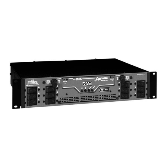
- Page 1 RD - 121 RACK MOUNT DIMMER OWNERS MANUAL REVISION 1.2 02/28/2005 www.lightronics.com Lightronics Inc. 509 Central Drive, Virginia Beach, VA 23454 (757) 486-3588...
-
Page 2: Table Of Contents
TO SAVE A CHASE STEP MAINTENANCE AND REPAIR TROUBLESHOOTING OWNER MAINTENANCE OPERATING AND MAINTENANCE ASSISTANCE MULTIPLEX CONNECTIONS - DIAGRAM DMX-512 CONNECTIONS - DIAGRAM PIN ASSIGNMENTS OF CONTROL SIGNAL CONNECTORS www.lightronics.com Lightronics Inc. 509 Central Drive, Virginia Beach, VA 23454 (757) 486-3588... -
Page 3: Unit Description And Functions
Power enters the RD-121 through a knockout sized hole at the rear of the unit. Remove the top cover and install an appropriate cable clamp in the knockout hole. Pass the power cables through the hole. Behind the hole is a terminal block with three lugs. -
Page 4: Output Channel Connections
("LMX" or compatible), plug the control cable into the 3 pin "XLR" connector. If you are using the DMX- 512 protocol, plug your 5 pin DMX control cable into the 5 pin to 9 pin adapter supplied with the RD-121 and plug the 9 pin connector into the upper 9 pin connector on the rear of the dimmer. -
Page 5: Resetting The Unit
RESETTING THE UNIT The RD-121 may be reset to a "factory provided" configuration by holding down the MENU button on the front panel for about 5 seconds. A message "SYSTEM RESET" will appear on the front panel LCD display. Release the MENU button when you see the message. -
Page 6: Normal Operation
TO ACTIVATE A STORED SCENE: A scene previously stored in the RD-121 is activated by connecting together pins 5 and 9 of either DB9 connector. The DB9 connectors are on the rear of the dimmer. This may be done via a remotely located switch. The activated scene will remain active as long as pins 5 and 9 on the DB9 connectors remain connected together. -
Page 7: Notes About Internal Scene
5 and 9 on the DB9 connectors remain connected together. In addition to activating a chase, the RD-121 can be set to ignore the remote switch or use it to activate a scene. -
Page 8: Controlling Chaser Characteristics
** Overrides remote switch setting The default setting is the factory set value. All of these characteristics can be set via the RD-121 menu system. See the diagram STRUCTURE OF MENU SYSTEM for a complete layout of menu system operation. -
Page 9: Structure Of The Menu System
= Set Chase run Normal/Single (Normal = Continuous) Normal SELECT = Exit MENU ChsPwr = Set Chase at Power Up (Normal = OFF, PwrUp - ON) Normal SELECT = Exit MENU www.lightronics.com Lightronics Inc. 509 Central Drive, Virginia Beach, VA 23454 (757) 486-3588... -
Page 10: Creating Your Own Custom Chase Pattern
The chase step is then recorded. This action is then repeated for each additional step to be recorded. The channel intensities can be set either from the RD-121 front panel as in manual operation or by using a control console. -
Page 11: Maintenance And Repair
Service by other than Lightronics authorized agents may void your warranty. OPERATING AND MAINTENANCE ASSISTANCE If service is required, contact the dealer from whom you purchased the equipment or contact Lightronics, Service Department, 509 Central Drive, Virginia Beach, VA 23454 TEL 757 486 3588. -
Page 12: Multiplex Connections - Diagram
5 pin XLR connectors (SHIELDED data cable) DIMMER DMX-512 protocol 5 pin to 9 pin adapter Supplied with each unit DIMMER Ribbon Cable Jumper Supplied with each unit To other units www.lightronics.com Lightronics Inc. 509 Central Drive, Virginia Beach, VA 23454 (757) 486-3588... -
Page 13: Pin Assignments Of Control Signal Connectors
Page 13 of 13 RD - 121 RACK MOUNT DIMMER OWNERS MANUAL Version 1.2 02/28/2005 PIN ASSIGNMENTS OF CONNECTORS USED ON THE RD-82 AND RD-121 DMX-512 CONNECTOR MULTIPLEX ( LMX) CONNECTOR 3 PIN MALE XLR 5 PIN MALE XLR Used on adapter cable... - Page 14 A) If service is required, you may be asked to provide proof of purchase from an authorized Lightronics dealer. B) The FIVE YEAR WARRANTY is only valid if the warranty card is returned to Lightronics accompanied with a copy of the original receipt of purchase within 30 DAYS of the purchase date, if not then the TWO YEAR WARRANTY applies.
Need help?
Do you have a question about the RD-121 and is the answer not in the manual?
Questions and answers