Table of Contents
Advertisement
Quick Links
Advertisement
Table of Contents

Related Manuals for Lenovo 30BJ


Summary of Contents for Lenovo 30BJ
- Page 1 P320 User Guide Machine Types: 30BJ, 30BK, and 30BS...
- Page 2 Important safety information” on page iii and Appendix G “Notices” on page 129. Fourth Edition (May 2018) © Copyright Lenovo 2017, 2018. LIMITED AND RESTRICTED RIGHTS NOTICE: If data or software is delivered pursuant to a General Services Administration “GSA”...
-
Page 3: Table Of Contents
(Windows 7 only) ..Enabling or disabling the automatic power-on An introduction to Lenovo programs ..of your computer ... . - Page 4 Safety and warranty ... 109 Chapter 6. Troubleshooting, Lenovo Web site... . . 109 diagnostics, and recovery ..45 Lenovo Support Web site .
-
Page 5: Read This First: Important Safety Information
Replacement parts approved for customer installation are referred to as Customer Replaceable Units, or CRUs. Lenovo provides documentation with instructions when it is appropriate for customers to install options or replace CRUs. You must closely follow all instructions when installing or replacing parts. -
Page 6: Static Electricity Prevention
When replacing CRUs, be cautious of sharp edges or corners that might cause injury. If you suffer an injury, seek medical care immediately. Static electricity prevention Static electricity, although harmless to you, can seriously damage computer components and options. Improper handling of static-sensitive parts can damage the part. When you unpack an option or CRU, do not open the static-protective package containing the part until the instructions direct you to install it. -
Page 7: Extension Cords And Related Devices
Your computer, power adapter, and many accessories produce some heat during normal operation. Extended contact with the body could cause discomfort or, potentially, a skin burn. © Copyright Lenovo 2017, 2018... -
Page 8: Computer Placement Notices
• Do not charge the battery or operate your computer, power adapter, or accessories near flammable materials or in explosive environments. • Ventilation slots, fans, and heat sinks are provided with the product for safety, comfort, and reliable operation. These features might inadvertently become blocked by placing the product on a bed, sofa, carpet, or other flexible surface. -
Page 9: Laser Compliance Statement
Disassembling of these components might cause fire or might even result in death. If you suspect a problem with one of these parts, contact a service technician. Lithium coin-cell battery notice DANGER Danger of explosion if battery is incorrectly replaced. © Copyright Lenovo 2017, 2018... -
Page 10: Using Earphones, Headphones, Or A Headset
2 can be dangerous due to excessive sound pressure levels. If your Lenovo computer came with headphones or earphones in the package, as a set, the combination of the headphones or earphones and the computer already complies with the specifications of EN 50332-1. If different headphones or earphones are used, ensure that they comply with EN 50332-1 (Clause 6.5... -
Page 11: Cleaning And Maintenance
Do not spray any liquid detergent directly on the computer or use any detergent containing flammable material to clean the computer. Spray the detergent on a soft cloth and then wipe the computer surfaces. © Copyright Lenovo 2017, 2018... - Page 12 P320 User Guide...
-
Page 13: Chapter 1. Product Overview
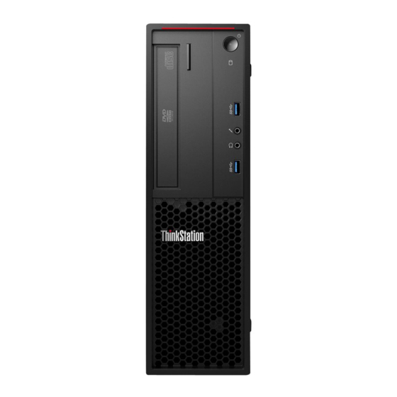
Card reader (some models) Optical-drive eject/close button Press the button to eject or close the tray of the optical drive. Power indicator When the power indicator is on, the computer is turned on. Power button © Copyright Lenovo 2017, 2018... -
Page 14: Rear View
Press the power button to turn on your computer. If your computer is unresponsive, you can turn off the computer by pressing and holding the power button for four or more seconds. Storage drive activity indicator This indicator shows the status of the internal storage drives (such as hard disk drives or solid-state drives). On: The storage drives are active and data is being transferred. - Page 15 Figure 2. Rear panel Power-cord connector VGA connector ® Serial connector DisplayPort connectors (2) USB 3.0 connectors (4) USB 2.0 connectors (2) Microphone connector Audio line-out connector Audio line-in connector PCIe card area* Optional serial connector Ethernet connector Cable-lock slots (2) PS/2 keyboard and mouse connectors (some models) Security-lock slot Padlock loop...
- Page 16 Use this connector to attach an external modem, a serial printer, or other devices that use a 9-pin serial connector. DisplayPort connector (2) Use this connector to attach a high-performance monitor, a direct-drive monitor, or other compatible devices. USB 3.0 connectors (4) Use this connector to attach a USB-compatible device, such as a USB keyboard, mouse, storage drive, or printer.
-
Page 17: Computer Components
Use this connector to attach a Personal System/2 (PS/2) keyboard or a PS/2 mouse. Security-lock slot Attach a Kensington-style cable lock to the security-lock slot to secure your computer. For more information, see “Attaching a Kensington-style cable lock” on page 29. Padlock loop Connect a padlock to secure your computer. -
Page 18: Parts On The System Board
Parts on the system board Note: The system board might look slightly different from the illustrations. The following illustration shows the locations of the parts on the system board. Figure 4. Parts on the system board 4-pin power connector PS/2 keyboard and mouse connector Microprocessor Microprocessor fan connector Battery... -
Page 19: Internal Storage Drives
PCIe x1 card slot 4 PCIe x4 card slot 3 (negotiable link width x4, x1) PCIe x1 card slot 2 PCIe x16 card slot 1 (graphic card available on some models) System fan connector Cover presence switch connector (intrusion switch connector) Internal storage drives Internal drives are devices that your computer uses to read and store data. -
Page 20: Machine Type And Model Label
PCIe solid-state drives or other PCIe cards might be installed in the slots. Machine type and model label The machine type and model label identifies your computer. When you contact Lenovo for help, the machine type and model information helps support technicians to identify your computer and provide faster service. -
Page 21: Computer Features
Figure 6. Machine type and model label Computer features For your specific computer model, some features might vary or not apply. Information about your computer • To view basic information (such as microprocessor and memory information) about your computer, do the following: 1. - Page 22 • Card reader (9-in-1, available on some models) • Optical drive (available on some models) • Serial Advanced Technology Attachment (SATA) hard disk drive • SATA hybrid drive (available on some models) • SATA solid-state drive (available on some models) •...
- Page 23 • Hard-disk-drive bays • Memory slots • Optical-drive bays • PCIe x1 card slots • PCIe x4 card slot (negotiable link width x4, x1) • PCIe x16 card slot (graphic card available on some models) Power supply Your computer comes with one of the following power supplies: •...
-
Page 24: Computer Specifications
Your computer is preinstalled with Windows 7 or Windows 10 operating system. Additional operating systems might be identified by Lenovo as compatible with your computer. To determine if an operating system has been certified or tested for compatibility, check the Web site of the operating system provider. -
Page 25: Programs
Accessing a program on your computer Note: For Windows 7, depending on your computer model, some of the Lenovo programs might be ready to be installed, so you must install them manually. Then, you can access and use these programs. -
Page 26: Installing A Program That Is Ready To Be Installed (Windows 7 Only)
An introduction to Lenovo programs This section provides information about the major Lenovo programs available on your operating system. Note: Depending on your computer model, some of the following programs might not be available. - Page 27 Lenovo Solution Center The Lenovo Solution Center program enables you to troubleshoot and resolve computer problems. It combines diagnostic tests, system information (Windows 7) collection, security status, and support information, along with hints and tips for maximum system performance. Lenovo ThinkVantage Tools The Lenovo ThinkVantage Tools program provides easy access to various tools to help your work more easily and securely.
- Page 28 P320 User Guide...
-
Page 29: Chapter 2. Using Your Computer
When you register your computer with Lenovo, you enter required information into a Lenovo database. The information enables Lenovo to contact you when there is a recall or other severe problem and provide quicker service when you call Lenovo for help. In addition, some locations offer extended privileges and services to registered users. -
Page 30: Playing And Removing A Disc
• To remove dust or fingerprints, wipe the disc with a clean, soft cloth from the center to the outside. Wiping the disc in a circular direction might cause loss of data. • Do not write or stick paper on the disc. •... -
Page 31: Connecting To A Network
2. Open Windows Media Player. See “Accessing a program on your computer” on page 13. 3. Follow the instructions on the screen. • Burn a disc from an ISO file. 1. Insert a recordable disc into the optical drive that supports recording. 2. - Page 32 To connect to a Bluetooth-enabled device, do the following: 1. Turn on the Bluetooth feature of your computer. Ensure that the Bluetooth-enabled device is located within a distance of about 10 m (32.8 ft) from your computer. 2. Click the Bluetooth icon in the Windows notification area on the taskbar. Then, click Add a Device and follow the instructions on the screen.
-
Page 33: Chapter 3. You And Your Computer
For more information about power cords or power adapters, see “Power cords and power adapters” on page Comfort Although no single working position is ideal for everyone, here are a few guidelines to help you find a position that suits you best. The following figure sets an example for your reference. © Copyright Lenovo 2017, 2018... -
Page 34: Accessibility Information
Accessibility information Lenovo is committed to providing users who have hearing, vision, and mobility limitations with greater access to information and technology. This section provides information about the ways these users can get the most out of their computer experience. You also can get the most up-to-date accessibility information from the following Web site: https://www.lenovo.com/accessibility... - Page 35 To use Ease of Access Center, do the following: 1. Click the Start button to open the Start menu. 2. Depending on your Windows version, do one of the following: • For Windows 7: Click Control Panel. View Control Panel by Large icons or Small icons, and then click Ease of Access Center.
- Page 36 • Using PDFs with screen readers: https://www.adobe.com/accessibility.html?promoid=DJGVE • Using the JAWS screen reader: https://www.freedomscientific.com/Products/Blindness/JAWS • Using the NVDA screen reader: https://www.nvaccess.org/ Screen resolution You can make the text and images on your screen easier to read by adjusting the screen resolution of your computer.
-
Page 37: Cleaning Your Computer
Then, you can type a message on your computer and send it to the telephone. Documentation in accessible formats Lenovo provides electronic documentation in accessible formats, such as properly tagged PDF files or HyperText Markup Language (HTML) files. Lenovo electronic documentation is developed to ensure that visually impaired users can read the documentation through a screen reader. -
Page 38: Good Maintenance Practices
The cause of a problem might be change in hardware, change in software, or any other actions that might have taken place. A log book can help you or a Lenovo technician determines the cause of a problem. • Create Product Recovery discs. -
Page 39: Moving Your Computer
3. Follow the instructions on the screen. Note: The device drivers provided by Windows Update might not be tested by Lenovo. It is recommended that you get device drivers by using Lenovo programs or from the Lenovo Web site at http://www.lenovo.com/... - Page 40 P320 User Guide...
-
Page 41: Chapter 4. Security
The cable lock also locks the buttons used to open the computer cover. This is the same type of lock used with many notebook computers. You can order such a cable lock directly from Lenovo by searching for Kensington at: http://www.lenovo.com/support... -
Page 42: Attaching A Cable Lock
Figure 8. Kensington-style cable lock Attaching a cable lock A cable lock can be used to secure devices, such as the keyboard and the mouse, by locking the device cables to your computer. The cable lock attaches to the cable-lock slots on the rear of your computer. To attach a cable lock, do the following: 1. -
Page 43: Viewing And Changing Security Settings In The Setup Utility Program
Figure 9. Cable lock Viewing and changing security settings in the Setup Utility program To view and change security settings in the Setup Utility program, do the following: 1. Start the Setup Utility program. See “Starting the Setup Utility program” on page 35. 2. -
Page 44: Using Fingerprint Authentication
• For Windows 7: Use the Fingerprint Manager Pro or ThinkVantage Fingerprint Software program provided by Lenovo. To open the program, see “Accessing a program on your computer” on page 13. For more information about using the program, refer to the help system of the program. -
Page 45: Protecting Data Against Viruses
Your computer is preinstalled with an antivirus program to help you guard against, detect, and eliminate viruses. Lenovo provides a full version of antivirus software on your computer with a free 30-day subscription. After 30 days, you must renew the license to continue receiving the antivirus software updates. - Page 46 P320 User Guide...
-
Page 47: Chapter 5. Advanced Configuration
Then, select Yes in the window displayed, and press Enter. Enabling or disabling the automatic power-on of your computer The Automatic Power On item in the Setup Utility program provides various options for you to make your computer start up automatically. © Copyright Lenovo 2017, 2018... -
Page 48: Enabling Or Disabling The Erp Lps Compliance Mode
Then, select Yes in the window displayed, and press Enter. Enabling or disabling the ErP LPS compliance mode Lenovo computers meet the eco-design requirements of the ErP Lot 3 regulation. For more information, go http://www.lenovo.com/ecodeclaration You can enable the ErP LPS compliance mode in the Setup Utility program to reduce the consumption of electricity when your computer is off or in sleep mode. -
Page 49: Enabling Or Disabling The System To Record Thermal Alert Logs
1. Start the Setup Utility program. 2. Select Power ➙ Intelligent Cooling Engine (ICE) and press Enter. 3. Select ICE Performance Mode and press Enter. 4. Select Better Acoustic Performance or Better Thermal Performance as desired and press Enter. 5. To save settings and exit the Setup Utility program, press F10 or Fn+F10 (depending on the keyboard settings). -
Page 50: Using Bios Passwords
4. Select Yes in the window displayed and press Enter to confirm your selection. 5. To save settings and exit the Setup Utility program, press F10 or Fn+F10 (depending on the keyboard settings). Then, select Yes in the window displayed, and press Enter. Using BIOS passwords By using the Setup Utility program, you can set passwords to prevent unauthorized access to your computer and data. -
Page 51: Selecting A Startup Device
Setting, changing, or deleting a password To set, change, or delete a password, do the following: 1. Start the Setup Utility program. 2. Select Security. 3. Depending on the password type, select Set Power-On Password, Set Administrator Password, or Hard Disk Password and press Enter. 4. -
Page 52: Exiting The Setup Utility Program
To update the BIOS, do the following: 1. Go to http://www.lenovo.com/support 2. To update the BIOS from your operating system, download the flash BIOS update driver according to your operating system version. To update the BIOS from a flash update disc, download the ISO image version (used to create a flash update disc). -
Page 53: Configuring Raid
Note: If you want to update the BIOS from a flash update disc, the installation instructions might not provide the instructions on how to record the update disc. Recovering from a BIOS update failure To recover from a BIOS update failure, do the following: 1. -
Page 54: Creating Raid Volumes
To enable SATA RAID functionality, do the following: 1. Start the Setup Utility program. See “Starting the Setup Utility program” on page 35. 2. Select Devices ➙ ATA Drive Setup. 3. Select Configure SATA as and press Enter. 4. Select RAID and press Enter. 5. - Page 55 4. When prompted, press Y to confirm the reset action. 5. After resetting your hard disk drives to non-RAID, you can: • See “Deleting RAID volumes” on page 42 for RAID volume deletion. • See “Creating RAID volumes” on page 42 for RAID volume creation. •...
- Page 56 P320 User Guide...
-
Page 57: Chapter 6. Troubleshooting, Diagnostics, And Recovery
4. Run the diagnostic program. If the diagnostic program does not resolve your problem, continue with the next step. 5. Recover your operating system. 6. If none of these actions solve your problem, contact the Lenovo Customer Support Center. For a list of Lenovo Support phone numbers, go to http://www.lenovo.com/support/phone Startup problems The computer does not start up when you press the power button. -
Page 58: Startup Problems
Ensure that no keys are stuck. Startup problems The computer does not start up when you press the power button. Solutions: Ensure that: • The power cord is correctly connected to the rear of the computer and to a working electrical outlet. •... -
Page 59: Cd Or Dvd Problems
• Ensure that the program you are running is designed for use on the Windows operating system. If the program is designed to run in DOS, the program does not use the Windows sound feature. The program must be configured to use Sound Blaster Pro or Sound Blaster emulation. •... -
Page 60: Intermittent Problems
A DVD movie does not play. Solutions: • Ensure that the disc surface is clean and not scratched. • Check the disc or package for regional coding. You might need to purchase a disc with coding for the region where you are using your computer. No audio or only an intermittent audio comes out while a DVD movie is playing. -
Page 61: Ethernet Lan Problems
The computer cannot start up from the correct storage drive or the message “No Operating System Found” is displayed. Solutions: • Ensure that the signal cables and power cables for all the storage drives are connected correctly. • Ensure that the computer starts up from the correct storage drive. Set the storage drive, on which the operating system resides, as the first startup device in the Setup Utility program. -
Page 62: Wireless Lan Problem
The Wake On LAN feature does not work. Solution: Enable the Wake On LAN feature in the Setup Utility program. Wireless LAN problem Note: The wireless LAN feature is available only on some models. The wireless LAN feature does not work. Solutions: •... -
Page 63: Performance Problems
1. Click the Start button to open the Start menu. 2. Click Settings ➙ Devices ➙ Bluetooth & other devices. 3. Turn on the Bluetooth switch to enable the Bluetooth feature. • Update or reinstall the Bluetooth driver. See “Keeping your computer current” on page 26. No sound comes from the Bluetooth headset or headphones. -
Page 64: Serial Connector Problem
• Right-click a blank area on the taskbar and open Task Manager. Then, end some tasks you are not performing. • Install additional memory modules. To purchase memory modules, go to: http://www.lenovo.com Serial connector problem USB device problems A USB device cannot be accessed. -
Page 65: Software And Driver Problems
Diagnosing problems with Lenovo Solution Center on the Windows 7 operating system Lenovo Solution Center is preinstalled on your computer and also is available for download at: http://www.lenovo.com/diags Notes: •... -
Page 66: Recovery Information
• If you are unable to isolate and repair the problem yourself after running Lenovo Solution Center, save and print the log files created by the program. You need the log files when you speak to a Lenovo technical support representative. - Page 67 1. Select the recovery medium as the startup device. 2. Follow the instructions on the screen to choose the appropriate recovery solution. • Use the recovery disc set provided by Lenovo to restore the entire storage drive to the factory-default settings.
- Page 68 – If your computer does not come with the recovery USB key, contact the Lenovo Customer Support Center to order a recovery USB key. P320 User Guide...
-
Page 69: Chapter 7. Hardware Removal And Installation
3. Remove the two screws that secure the computer cover. 4. Press the cover-release button on the side of the computer and slide the cover to the rear of the computer to remove the cover. © Copyright Lenovo 2017, 2018... -
Page 70: Installing Or Replacing Hardware
• When installing or replacing an option, use the appropriate instructions in this section along with the instructions that come with the option. • In most areas of the world, Lenovo requires the return of the defective CRU. Information about this will come with the CRU or will come a few days after the CRU arrives. -
Page 71: Pcie Card
2. Release the three plastic tabs on the top of the front bezel and pivot the front bezel outward to remove it from the computer. Figure 11. Removing the front bezel 3. To reinstall the front bezel, first align the three plastic tabs on the bottom of the front bezel with the corresponding holes in the chassis. - Page 72 Your computer has two PCIe x1 card slots, one PCIe x4 card slot (negotiable link width x4, x1), and one PCIe x16 graphics card slot. To install or replace a PCIe card, do the following: 1. Prepare your computer. See “Preparing your computer and removing the computer cover” on page 57. 2.
-
Page 73: M.2 Solid-State Drive
Figure 15. Installing a PCIe card Note: If you are installing a PCIe x16 graphics card, ensure that the memory-slot retaining clips are closed before you install the card to avoid any interference during the installation. What to do next: •... - Page 74 b. The heat sink is secured by two mounting studs. Pinch the clips of the studs inward and push the studs upward to release the heat sink. Then, lift the heat sink off the M.2 solid-state drive adapter Figure 16. Removing the heat sink from the M.2 solid-state drive adapter c.
- Page 75 Figure 18. Installing the thermal pad 5. Insert the new M.2 solid-state drive into the M.2 slot. Then, insert the plug of the retention latch into the hole to secure the new drive. Figure 19. Installing the M.2 solid-state drive 6.
-
Page 76: Coin-Cell Battery
Figure 20. Installing the heat sink 7. Install the M.2 solid-state drive adapter into the appropriate PCIe card slot on the system board. See “PCIe card” on page 59. Note: It is recommended that you install the M.2 solid-state drive adapter into the PCIe x4 card slot. See “Parts on the system board”... -
Page 77: Memory Module
Figure 21. Removing the old coin-cell battery 4. Install a new coin-cell battery. Figure 22. Installing a new coin-cell battery 5. Reinstall the computer cover and connect the cables. See “Completing the parts replacement” on page 105. Note: When the computer is turned on for the first time after replacing the coin-cell battery, an error message might be displayed. - Page 78 Figure 23. Memory module installation order To install or replace a memory module, do the following: 1. Prepare your computer. See “Preparing your computer and removing the computer cover” on page 57. 2. Lay the computer on its side for easier access to the system board. 3.
- Page 79 Figure 24. Removing a memory module • If you are installing a memory module, open the retaining clips of the memory slot into which you want to install the memory module. Figure 25. Opening the retaining clips 6. Position the new memory module over the memory slot. Ensure that the notch on the memory module is aligned with the key in the slot.
-
Page 80: Optical Drive
Figure 26. Installing a memory module 7. Reinstall the PCIe x16 graphics card if you have removed it. What to do next: • To work with another piece of hardware, go to the appropriate section. • To complete the installation or replacement, go to “Completing the parts replacement” on page 105. Optical drive Attention: Do not open your computer or attempt any repair before reading and understanding the “Read this first: Important safety information”... - Page 81 Figure 27. Pivoting the drive bay assembly upward 4. Depending on whether you are installing or replacing an optical drive, do one of the following: • If you are installing a new optical drive, do the following: a. Remove the metal static shield from the bay. b.
- Page 82 Figure 28. Removing the optical drive 5. Install the optical-drive retainer on the side of the new optical drive. Figure 29. Installing the optical-drive retainer 6. Slide the new optical drive into the drive bay until the optical drive snaps into position. P320 User Guide...
-
Page 83: Hard Disk Drive In The Front-Access Storage Enclosure
Figure 30. Installing the optical drive 7. Connect any required cables. For the optical drive, connect the power cable and the signal cable to the rear of the optical drive. What to do next: • To work with another piece of hardware, go to the appropriate section. •... - Page 84 2. Unlock the enclosure cover with the provided key as shown. Press the notch to open the enclosure cover. Figure 31. Opening the front-access storage enclosure cover 3. Press the pit on the bracket cover, and then grasp the tilted cover to pull the bracket out of the front- access storage enclosure.
- Page 85 Figure 34. Installing the 3.5-inch storage drive into the bracket 6. Slide the bracket with the new 3.5-inch storage drive into the front-access storage enclosure until it snaps into position. Press the notch to secure the enclosure cover and lock the enclosure cover with the key.
- Page 86 Figure 36. Opening the front-access storage enclosure cover 3. Press the pit on the bracket cover, and then grasp the tilted cover to pull the bracket out of the front- access storage enclosure. Figure 37. Removing the bracket from the front-access storage enclosure 4.
- Page 87 Figure 39. Removing the metal bracket from the plastic frame of the converter c. Carefully flex both sides of the metal bracket to remove the storage drive from the bracket. Figure 40. Removing the storage drive from the metal bracket 5.
- Page 88 Figure 42. Inserting the metal bracket into the plastic frame of the converter c. Push the metal bracket down until the tab is slightly curved. Then, push the bracket with the storage drive forward as shown until the tab snaps into position. Figure 43.
-
Page 89: Device In The Multi-Drive Conversion Kit
Figure 44. Installing the converter with the 2.5-inch storage drive into the plastic bracket 6. Slide the plastic bracket with the new 2.5-inch storage drive into the front-access storage enclosure until it snaps into position. Press the notch to secure the enclosure cover and lock the enclosure cover with the key. - Page 90 Note: The instructions on how to install or replace a slim optical drive in the kit also applies to the Slim Optical Drive Adapter. 1. Slide the kit out of the chassis. See “Optical drive” on page 68. 2. If you are replacing an old slim optical drive, do the following: a.
- Page 91 Figure 48. Installing the bracket to the new slim optical drive 4. Insert the new slim optical drive into the kit until you hear a click. The slim optical drive is secured in place. Figure 49. Installing the slim optical drive into the kit 3.5-inch internal storage drive To install or replace a 3.5-inch internal storage drive in the kit, do the following: 1.
- Page 92 Figure 50. Opening the kit from the rear 3. If you are replacing an old 3.5-inch internal storage drive, do the following: a. Press both clips simultaneously toward each other and slide the 3.5-inch internal storage drive out of the rear of the kit. Figure 51.
- Page 93 Figure 52. Flexing both sides of the bracket to remove the 3.5-inch internal storage drive 4. Flex the bracket and align pins , and on the bracket with the corresponding holes in the new 3.5-inch internal storage drive. Then install a new 3.5-inch internal storage drive into the bracket. Do not touch the circuit board on the internal storage drive.
- Page 94 Figure 54. Sliding the new 3.5-inch internal storage drive into the kit 6. Pivot the rear cover of the kit inward until you hear a click. The rear cover is secured in place. Figure 55. Pivoting the rear cover inward 2.5-inch internal storage drive To install or replace a 2.5-inch internal storage drive in the kit, do the following: 1.
- Page 95 Figure 56. Opening the kit from the rear 3. If you are replacing an old 2.5-inch internal storage drive, do the following: a. Press both clips simultaneously toward each other and slide the 2.5-inch internal storage drive out of the rear of the kit. Figure 57.
- Page 96 4. Flex the bracket and align pins , and on the bracket with the corresponding holes in the new 2.5-inch internal storage drive. Then install a new 2.5-inch internal storage drive into the bracket. Do not touch the circuit board on the internal storage drive.
- Page 97 Figure 61. Pivoting the rear cover inward Replacing a 3.5-inch internal storage drive with a 2.5-inch internal storage drive To replace a 3.5-inch internal storage drive with a 2.5-inch internal storage drive, do the following: 1. Ensure that the 3.5-inch internal storage drive is removed from the bracket first. See “3.5-inch internal storage drive”...
- Page 98 Figure 63. Pivoting the bracket 4. Fold the bracket as shown. Figure 64. Folding the bracket 5. Insert tabs into the corresponding slots until you hear a click. Ensure that the tab is secured in place. P320 User Guide...
- Page 99 Figure 65. Inserting tabs into the corresponding slots 6. Install a 2.5-inch internal storage drive into the bracket. See “2.5-inch internal storage drive” on page 82. Replacing a 2.5-inch internal storage drive with a 3.5-inch internal storage drive To replace a 2.5-inch internal storage drive with a 3.5-inch internal storage drive, do the following: 1.
- Page 100 Figure 67. Releasing tabs , and from the corresponding slots 4. Unfold the bracket as shown. Figure 68. Unfolding the bracket 5. Insert tabs into the corresponding slots. Ensure that the tab is secured in place. P320 User Guide...
-
Page 101: Solid-State Drive
Figure 69. Inserting tabs into the corresponding slots 6. Install a 3.5-inch internal storage drive into the bracket. See “3.5-inch internal storage drive” on page 79. What to do next: • To work with another piece of hardware, go to the appropriate section. •... - Page 102 Figure 70. Installing the solid-state drive into the storage converter 3. Remove the 3.5-inch storage drive bracket out of the chassis. 4. To install the storage converter into the 3.5-inch storage drive bracket, flex the bracket and align pin , pin , and pin on the bracket with the corresponding holes in the storage converter.
- Page 103 Replacing the solid-state drive To replace the solid-state drive, do the following: 1. Prepare your computer. See “Preparing your computer and removing the computer cover” on page 57. 2. Locate the desired storage drive bay. See “Internal storage drives” on page 7. 3.
- Page 104 Figure 74. Installing the new solid-state drive into the storage converter 8. To install the storage converter into the 3.5-inch storage drive bracket, flex the bracket and align pin , pin , and pin on the bracket with the corresponding holes in the storage converter. Figure 75.
-
Page 105: Heat Sink And Fan Assembly
• To complete the installation or replacement, go to “Completing the parts replacement” on page 105. Heat sink and fan assembly Attention: Do not open your computer or attempt any repair before reading and understanding the “Read this first: Important safety information” on page iii. CAUTION: Avoid contact with hot components inside the computer. - Page 106 Figure 77. Screws that secure the heat sink and fan assembly 7. Lift the failing heat sink and fan assembly off the system board. Notes: • You might have to twist the heat sink and fan assembly gently to free it from the microprocessor. •...
-
Page 107: Power Supply Assembly
Figure 78. Installing the heat sink fan duct What to do next: • To work with another piece of hardware, go to the appropriate section. • To complete the installation or replacement, go to “Completing the parts replacement” on page 105. Power supply assembly Attention: Do not open your computer or attempt any repair before reading and understanding the “Read this first: Important safety information”... - Page 108 3. Gently pivot the two plastic retaining clips that secure the heat sink fan duct outward, and then lift the heat sink fan duct out of the chassis. Figure 79. Removing the heat sink fan duct 4. Press the release tab as shown and pivot the drive bay assembly upward.
- Page 109 Then, install the three screws to secure the new power supply assembly in place. Note: Use only screws provided by Lenovo. Chapter 7 Hardware removal and installation...
- Page 110 Figure 82. Installing the power supply assembly 10. Connect the new power supply assembly cables to all drives and the system board. See “Parts on the system board” on page 6. 11. Press the release tab as shown and pivot the drive bay assembly downward until it snaps into position.
-
Page 111: Primary Hard Disk Drive
12. Position the heat sink fan duct on the top of the heat sink as shown. Then, press the heat sink fan duct straight down until it snaps into position. Figure 84. Installing the heat sink fan duct What to do next: •... - Page 112 Figure 85. Pivoting the drive bay assembly upward 4. Locate the primary hard disk drive. See “Internal storage drives” on page 7. 5. Disconnect the signal cable and the power cable from the hard disk drive. 6. Pull the blue handle to slide the hard disk drive out of the drive cage. Figure 86.
-
Page 113: Secondary Hard Disk Drive
Figure 87. Installing the hard disk drive into the bracket 9. Slide the new hard disk drive into the drive cage until it snaps into position. Figure 88. Installing the primary hard disk drive 10. Connect the signal cable and the power cable to the new hard disk drive. What to do next: •... - Page 114 1. Prepare your computer. See “Preparing your computer and removing the computer cover” on page 57. 2. Remove the front bezel. See “Front bezel” on page 58. 3. Press the release tab as shown and pivot the drive bay assembly upward. Figure 89.
- Page 115 Figure 91. Positioning the cage onto the bottom of the primary hard-disk-drive bay 8. Slide the secondary hard-disk-drive cage to the left of the chassis until it snaps into position and the screw hole in the cage is aligned with the screw hole in the bay.
- Page 116 Figure 93. Installing the screw to secure the secondary hard disk drive cage 10. To install a new hard disk drive into the blue bracket, flex the bracket and align pin , pin , pin , and on the bracket with the corresponding holes in the hard disk drive. Do not touch the circuit board on the bottom of the hard disk drive.
-
Page 117: Completing The Parts Replacement
Figure 95. Installing the secondary hard disk drive 12. Connect the signal cable and the power cable to the new secondary hard disk drive. What to do next: • To work with another piece of hardware, go to the appropriate section. •... - Page 118 Figure 96. Pivoting the drive bay assembly downward 4. Position the computer cover on the chassis so that the rail guides on the bottom of the computer cover engage the rails on the chassis. Then, push the cover to the front of the computer until it snaps into position.
- Page 119 7. If a locking device is available, lock the computer cover. See “Locking your computer” on page 29. 8. Reconnect the external cables and power cords to the corresponding connectors on the computer. See “Hardware locations” on page 1. 9. Update the configuration of your computer. See “Using the Setup Utility program” on page 35. 10.
- Page 120 P320 User Guide...
-
Page 121: Chapter 8. Getting Information, Help, And Service
Chapter 8. Getting information, help, and service This chapter provides information about getting help and support from Lenovo. Information resources You can use the information in this section to access useful resources relating to your computing needs. Accessing the user guide in various languages To access the user guide in various languages, go to: https://support.lenovo.com... -
Page 122: Lenovo Support Web Site
• Engineering Change management - There might be changes that are required after a product has been sold. Lenovo or your reseller will make selected Engineering Changes (ECs) that apply to your hardware available. -
Page 123: Using Other Services
For technical assistance with the installation of or questions related to Service Packs for your preinstalled Microsoft Windows product, go to . You also can contact the Lenovo Customer https://support.microsoft.com Support Center for help. Some fees might apply. Purchasing additional services During and after the warranty period, you can purchase additional services. - Page 124 P320 User Guide...
-
Page 125: Appendix A. System Memory Speed
– Intel Pentium (for models with the Windows 10 operating system): G4560 – Intel Core: – For models with the Windows 10 operating system: i7-7700K, i7-7700, i5-7600, i5-7500, i5-7400, i3- 7300, i3-7100 – For models with the Windows 7 operating system: i7-6700, i5-6500, i5-6400, i3-6100 © Copyright Lenovo 2017, 2018... - Page 126 P320 User Guide...
-
Page 127: Appendix B. Supplemental Information About The Ubuntu Operating System
The LLW also is preinstalled on the computer. To access the LLW, go to the following directory: /usr/share/doc/lenovo-doc If you cannot view the LLW either from the Web site or from your computer, contact your local Lenovo office or reseller to obtain a printed version of the LLW. - Page 128 P320 User Guide...
-
Page 129: Appendix C. Regulatory Information
• Consult an authorized dealer or service representative for help. Lenovo is not responsible for any radio or television interference caused by using other than specified or recommended cables and connectors or by unauthorized changes or modifications to this equipment. - Page 130 Geräten), bzw. der EMV EU Richtlinie 2014/30/EU, für Geräte der Klasse B. Dieses Gerät ist berechtigt, in Übereinstimmung mit dem Deutschen EMVG das EG-Konformitätszeichen - CE - zu führen. Verantwortlich für die Konformitätserklärung nach Paragraf 5 des EMVG ist die Lenovo (Deutschland) GmbH, Meitnerstr. 9, D-70563 Stuttgart.
-
Page 131: Eurasian Compliance Mark
The ac power cord shipped with your product can be used only for this specific product. Do not use the ac power cord for other devices. Lenovo product service information for Taiwan Keyboard and mouse compliance statement for Taiwan Eurasian compliance mark Brazil audio notice Ouvir sons com mais de 85 decibéis por longos períodos pode provocar danos ao sistema auditivo. -
Page 132: Additional Regulatory Information
All regulatory notices are available on the Lenovo Support Web site in electronic format. To access electronic copies of the documentation, go to https:// support.lenovo.com... -
Page 133: Appendix D. Weee And Recycling Information
Collecting and recycling a disused Lenovo computer or monitor If you are a company employee and need to dispose of a Lenovo computer or monitor that is the property of the company, you must do so in accordance with the Law for Promotion of Effective Utilization of Resources. -
Page 134: Recycling Information For Brazil
If you need to replace it with a new one, contact your place of purchase or contact Lenovo for service. If you need to dispose of a disused lithium battery, insulate it with vinyl tape, contact your place of purchase or an industrial-waste-disposal operator, and follow their instructions. -
Page 135: Battery Recycling Information For The European Union
If the battery needs to be replaced, contact your place of purchase or contact Lenovo for service. If you need to dispose of a lithium battery, insulate it with vinyl tape, contact your place of purchase or a waste-disposal operator, and follow their instructions. - Page 136 P320 User Guide...
-
Page 137: Appendix E. Restriction Of Hazardous Substances (Rohs) Directive
For more information about Lenovo worldwide compliance on RoHS, go to: https://www.lenovo.com/rohs-communication China RoHS Turkish RoHS The Lenovo product meets the requirements of the Republic of Turkey Directive on the Restriction of the Use of Certain Hazardous Substances in Waste Electrical and Electronic Equipment (WEEE). © Copyright Lenovo 2017, 2018... - Page 138 Ukraine RoHS India RoHS RoHS compliant as per E-Waste (Management) Rules. Taiwan RoHS P320 User Guide...
-
Page 139: Appendix F. Energy Star Model Information
For more information about ENERGY STAR, go to: http://www.energystar.gov Lenovo encourages you to make efficient use of energy an integral part of your day-to-day operations. To help in this endeavor, set the following power-management features to take effect when your computer has been inactive for a specified duration: Table 1. - Page 140 4. Follow the instructions on the screen. P320 User Guide...
-
Page 141: Appendix G. Notices
Lenovo representative for information on the products and services currently available in your area. Any reference to a Lenovo product, program, or service is not intended to state or imply that only that Lenovo product, program, or service may be used. Any functionally equivalent product, program, or service that does not infringe any Lenovo intellectual property right may be used instead. - Page 142 P320 User Guide...
-
Page 143: Appendix H. Trademarks
Appendix H. Trademarks The following terms are trademarks of Lenovo in the United States, other countries, or both: Lenovo The Lenovo logo ThinkStation The ThinkStation logo ThinkVantage Microsoft, Windows, and Windows Media are trademarks of the Microsoft group of companies. - Page 144 P320 User Guide...
Need help?
Do you have a question about the 30BJ and is the answer not in the manual?
Questions and answers