
Related Manuals for Helios RM-PSW2KVA Series


Summary of Contents for Helios RM-PSW2KVA Series
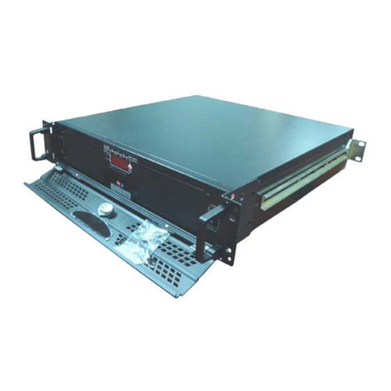
- Page 1 2U 19”/23”Rack-mount Model 2U 19”/23”Open Frame Cabinet model RM- PSW2KVA Series Pure Sine Wave Inverter User Manual RM-PSW122KVA/E RM-PSW242KVA/E RM-PSW482KVA/E RM-PSW1102KVA/E RM-PSW2202KVA/E www.heliosps.com...
-
Page 2: Table Of Contents
List of Contents 1. Features Application Electrical performance Mechanical drawings 2. Introduction Front panel operations Rear panel operations Installation Quick hook – up and testing AC safety grounding Making DC wiring connections Inverter operation Cooling fan working code 3. Maintenance 4. -
Page 3: Features
1. Features Pure sine wave output (THD < 3%) R Load By pass function Output frequency : 50 / 60Hz switch RS – 232 interface / remote controls port / Wire connection to PC Wired Remote control Thermostatically controlled cooling fan Advanced microprocessor Protection : Input low voltage Overload... -
Page 4: Electrical Performance
1-2 Electrical Performance Specification Model RM-PSW RM-PSW RM-PSW RM-PSW RM-PSW RM-PSW RM-PSW RM-PSW RM-PSW RM-PSW Item 122KVA 242KVA 482KVA 1102KVA 2202KVA 122KVAE 242KVAE 482KVAE 1102KVAE 2202KVAE (2U) (2U) (2U) (2U) (2U) (2U) (2U) (2U) (2U) (2U) Continuous Output 2000W Power 3Min 2300W Surge Rating... -
Page 5: Mechanical Drawings
1-3 Mechanical Drawings... -
Page 6: Introduction
2. Introduction: The power inverter series are the member of the most advanced line of mobile AC power systems available. To get the most out of the power inverter, it must be installed and used properly. Please read the instructions in this manual before installing and using this model. 2-1 Front Panel Operation: 2-1-1 Front view: 2-1-2 ON / OFF switch:... -
Page 7: Rear Panel Operations
2-2 Rear Panel Operation: 2-2-1 Ventilation openings: Do not obstruct, allow at least 3 inch for air flow. 2-2-2 Battery terminals: Connect to 12V / 24V / 48V battery or other 12V / 24V / 48V power Source. 【+】is positive,【-】is negative. Reverse polarity connection will blow internal fuse and may damage inverter permanently. - Page 8 WARNING! Any damages caused by using incorrect RS232 cable will be outside of our warranty scope. If you are not sure which one is correct RS232 cable, please purchase the correct RS232 cable from us directly. 2-2-4 Connect chassis ground terminal to earth or to vehicle chassis using # 8 AWG wire.
-
Page 9: Installation
2-3 Installation: Where to install; The power inverter should be installed in a location that meets the following requirements. 2-3-1 Dry – Do not allow water to drip or splash on the inverter. 2-3-2 Cool – Ambient air temperature should be between -20℃ and 50℃, the cooler the better. - Page 10 WARNING! Make sure all the DC connections are tight (torque to 9-10 ft-lbs, 11.7-13Nm). Loose connections will overheat and could result in a potential hazard. 2-4-3 Before proceeding further, carefully check that cable you have just connected negative terminal of inverter to the negative output power source. CAUTION! Reverse polarity connection will blow a fuse in inverter and may permanently damage the inverter.
-
Page 11: Ac Safety Grounding
2-5 AC Safety Grounding: During the AC wiring installation, AC input and output ground wires are connected to the inverter. The AC input ground wire must connect to the incoming ground from your AC utility source. The AC output ground wire should go to the grounding point for your loads (for example, a distribution panel of bus chassis). -
Page 12: Making Dc Wiring Connections
2-6. Marking DC Wiring Connections: Follow this procedure to connect the battery cables to the DC input terminals on the PSW2KVA/E Inverter. Your cables should be as short as possible (ideally, less than 10 feet / 3 meters) and large enough to handle the required Current in accordance with the electrical codes or regulations applicable to your installation. -
Page 13: Inverter Operation
2-7 Inverter Operation: To operate the power inverter, turn it on using the ON/OFF switch on the front panel. The power inverter is now ready to deliver AC power to your loads. If you are operating several loads from the power inverter, turn them on separately after the inverter has been turned on. - Page 14 Please have the accuracy of 6 functions of display, as below: Function WATT TEMP Frequency 100-120 200-240 10-16 20-32 42-62 90-140 180-275 Range 0-20A 0-2KW 0-120℃ 50Hz 60Hz Accuracy ± 1% ± 1% 1% ± 0.5A ± 3% ± 2% ± 2% ± 2% ± 2% ±...
-
Page 15: Cooling Fan Working Code
2-8 Cooling fan working code: Cooling fan of inverter is through detecting output power and over temperature situation to work. When start to turn on the inverter and output power is under 300W, the cooling fan does not start running. It complies with saving energy sources requirement. Until, output power is up to 300W, the cooling fan will start to work in order to drop the inner temperature. -
Page 16: Warranty
Problem and Symptoms Possible Cause Solution Low output voltage Using average reading Use true RMS reading meter (110V: 95-105VAC voltmeter and cable 220V: 190-210VAC) (Ref. point 2-4-7) Load Display OLP flash. Overload Reduce load. No output voltage. Low / High input voltage. Recharge battery, And fault Input voltage. -
Page 17: General Safety Precautions
6. Important Safety Instructions WARNING! Before you install and use your inverter, be to read and save these safety instructions. 6-1 General Safety Precautions 6-1-1 Do not expose the -PSW2KAV/E Inverter to rain, snow, spray, bilge or dust. To reduce risk of hazard, do not cover or obstruct the ventilation openings. Do not install the -PSW2KVA/E Inverter in a zero-clearance compartment. -
Page 18: Appendices A
7. Appendices A 7-1. Dip Switch (at the left side of inverter) FREQ. (Hz) BAUD RATE POWER SAVING ACV-ADJ H--------L 2400 DISABLE 240V 200V H--------L 4800 ENABLE 120V 100V ---- ---- 9600 ---- ----- ---- ---- ---- 19200 ---- ----- ---- S1: Freq (Hz) S2/S3: Baud Rate...
Need help?
Do you have a question about the RM-PSW2KVA Series and is the answer not in the manual?
Questions and answers