
Related Manuals for Helios RM-UIPSW3KVA Series


Summary of Contents for Helios RM-UIPSW3KVA Series
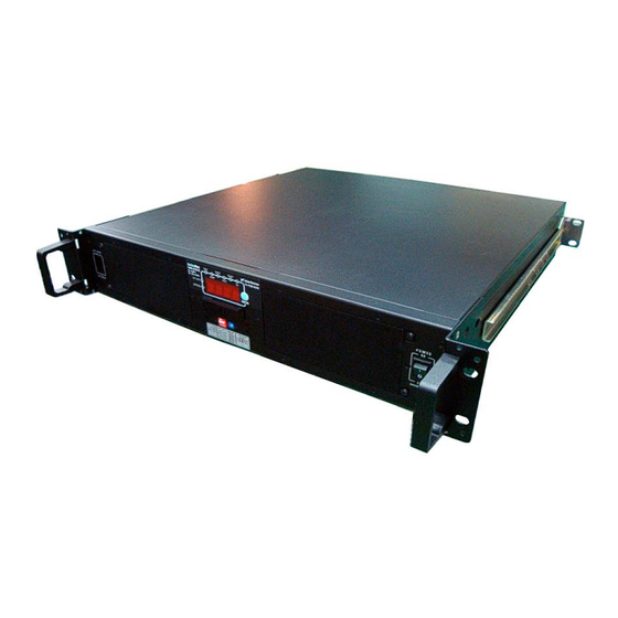
- Page 1 2U 19”/23”Rack-mount Model RM - UIPSW3KVA Series Pure Sine Wave Inverter User Manual www.heliosps.com: New Zealand: sales@heliosps.co.nz - Australia: sales@heliosps.com.au - Asia & ME: sales@heliosps.asia...
-
Page 2: Table Of Contents
List of Contents 1. Features Application Electrical performance Mechanical drawings 2. Introduction Front panel operations Rear panel operations Installation Quick hook – up and testing AC safety grounding Making DC wiring connections Inverter operation Cooling fan working code 3. Maintenance 4. -
Page 3: Features
1. Features n Pure sine wave output (THD < 3%) R Load n By pass function n Inverter mode / UPS mode n Output frequency: 50 / 60Hz switch n RS – 232 interface / Remote controls port / Wire connection to PC n... -
Page 4: Electrical Performance
1-2 Electrical Performance Model Specification UIPSW RM -UIPSW RM -UIPSW RM UIPSW RM -UIPSW RM -UIPSW RM -UIPSW RM -UIPSW RM -UIPSW RM -UIPSW Item 123KVA 243KVA 483KVA 1103KVA 2203KVA 123KVAE 243KVAE 483KVAE 1103KVAE 2203KVAE Continuous Output 3000W Power 3Min. 3200W Surge Rating... -
Page 5: Mechanical Drawings
1-3 Mechanical Drawings... -
Page 6: Introduction
2. Introduction: The power inverter series are the member of the most advanced line of mobile AC power systems available. To get the most out of the power inverter, it must be installed and used properly. Please read the instructions in this manual before installing and using this model. 2-1 Front Panel Operation : 2-1-1 Front view : 2-1-2 ON / OFF switch :... -
Page 7: Rear Panel Operations
2-2 Rear Panel Operation : 2-2-1 Ventilation openings : Do not obstruct, allow at least 3 inch for air flow. 2-2-2 Battery terminals : Connect to 12V / 24V / 48V solar panel or other 12V / 24V / 48V power Source. 【+】is positive,【-】is negative. - Page 8 WARNING! Any damages caused by using incorrect RS232 cable will be outside of our warranty scope. If you are not sure which one is correct RS232 cable, please purchase the correct RS232 cable from us directly. 2-2-4 Connect chassis ground terminal to earth or to vehicle chassis using # 8 AWG wire. WARNING! Operation of the inverter without a proper ground connection may result in an electrical safety hazard.
-
Page 9: Installation
2-3 Installation: Where to install. The power inverter should be installed in a location that meets the following requirements. 2-3-1 Dry – Do not allow water to drip or splash on the inverter. 2-3-2 Cool – Ambient air temperature should be between -20℃ and 50℃, the cooler the better. -
Page 10: Ac Safety Grounding
WARNING! Make sure all the DC connections are tight (torque to 9-10 ft-lbs, 11.7-13Nm). Loose connections will overheat and could result in a potential hazard. 2-4-3 Before proceeding further, carefully check that cable you have just connected negative terminal of inverter to the negative output power source. CAUTION ! Reverse polarity connection will blow a fuse in Inverter and may permanently damage the inverter. -
Page 11: Making Dc Wiring Connections
2-5-1 Neutral Grounding (GFCI’s) : 2-5-1-1 120V models: The neutral conductor of the AC output circuit of the Inverter is automatically connected to the safety ground during inverter operation. This conforms to national electrical code requirements that separately derived AC sources (such as inverter and generators ) have their neutral conductors tied to ground in the same way that the neutral conductor from the utility is tied to ground at the GFCI breaker panel. -
Page 12: Inline Fuse
Increasing your DC cable size will help improve the situation. Our company recommends the following cables for optimum inverter performance (apply both 120V and 230V versions) Model No Wire AWG Inline Fuse RM-UIPSW123KVA #4/0 400A RM-UIPSW123KVAE R M -UIPSW243KVA #2/0 200A R M -UIPSW243KVAE R M -UIPSW483KVA... - Page 13 2-7-2 Output Voltage Indicator : LED displays light on VAC as show as output Voltage value 2-7-3 Output Current Indictor LED displays light on AMP as show as output current value 2-7-4 Output Watts Indictor LED displays light on Watts as show as output Watts value 2-7-5 Input DC Voltage Indictor LED displays light on VDC as show as input DC voltage value 2-7-6 Temperature Indictor...
- Page 14 2-7-10 Over temp protection indicator : (OTP) The over temp indicator indicates that the power inverter has shut itself down because its temp has become overheated. The power inverter may overheat because it has been operated at power levels above its rating, or because it has been installed in a location which does not allow it to dissipate heat properly.
-
Page 15: Cooling Fan Working Code
2-7-13 Flow Chart Mains Power Load DC Input SWITCH UPS MODE INV MODE CONTROL (A) AC INPUT SWITCH (B) DC TO DC (C) DC TO AC (D) SWITCH (E) UPS MODE & INVERTER MODE UPS MODE: If DC to AC Inverter fails the UPS mode (mains input) takes over INVERTER MODE: If UPS mode (mains input) fails the Inverter takes over 2-8 Cooling fan working code: Cooling fan of inverter is through detecting output power and over temperature situation to... -
Page 16: Maintenance
3. Maintenance : Very little maintenance is required to keep your inverter operating properly. You should clean the exterior of the unit periodically with a dry cloth to prevent accumulation of dust and dirt. At the same time, tighten the Screws on the DC input terminals. 4. -
Page 17: Important Safety Instructions
negligence or other fault. 6. Important Safety Instructions WARNING ! Before you install and use your Inverter, be to read and save these safety instructions. 6-1 General Safety Precautions 6-1-1 Do not expose the Inverter to rain, snow, spray, bilge or dust. To reduce risk of hazard, do not cover or obstruct the ventilation openings. -
Page 18: Appendices A
7. Appendices A 7-1. Dip Switch (at the left side of inverter) S1: Freq (Hz) S2/S3: Baud Rate When you set up S1~S3, please reset the inverter and let update data through CPU. 7-2 Tune VR Tune VR ( VAC ) output voltage from 100 – 120 VAC or 200 – 240 VAC The VAC value will gradually increase;...
Need help?
Do you have a question about the RM-UIPSW3KVA Series and is the answer not in the manual?
Questions and answers