Table of Contents
Advertisement
Quick Links
Advertisement
Table of Contents

Subscribe to Our Youtube Channel
Related Manuals for Goulds Pumps VMP


Summary of Contents for Goulds Pumps VMP
- Page 1 Installation, Operation and Maintenance Instructions...
-
Page 3: Table Of Contents
10.1 Mechanical seal installation........................25 10.2 Primacyclamatic tank operation ......................25 11 Installing the Driver (VHS) ..........................26 11.1 Installation of hollow shaft right angle gear drive................... 26 11.2 Low profile discharge head........................26 VMP Installation, Operation and Maintenance Instructions... - Page 4 16.12 Turbine bowl - impeller wear ring removal ..................52 16.13 Bowl and suction sell bearing removal ....................52 16.14 Inspection and replacement ........................ 52 16.15 Turbine bowl and impeller wear rings reassemsly ................52 16.16 Bowl reassembly ..........................52 VMP Installation, Operation and Maintenance Instructions...
- Page 5 16.19 Thrust pot reassembly......................... 53 16.20 Pump reassembly..........................54 17 Recommended Lubricants ........................... 55 17.1 Recommended lubricants........................55 18 Parts List ................................ 56 18.1 General..............................56 18.2 Ordering parts ............................56 18.3 Return parts............................56 VMP Installation, Operation and Maintenance Instructions...
-
Page 6: Introduction And Safety
ITT Goulds pumps will provide safe, trouble-free service when properly installed, maintained, and operat- Safe installation, operation, and maintenance of ITT Goulds Pumps equipment are an essential end user responsibility. This Pump Safety Manual identifies specific safety risks that must be considered at all times during product life. -
Page 7: Safety
Trapped liquid can rapidly expand and result in a violent explosion and injury. ITT Goulds Pumps will not accept responsibility for physical injury, damage, or delays caused by a failure to observe the instructions for installation, operation, and maintenance contained in this Pump Safety Manual or the current IOM available at http://www.gouldspumps.com/literature. - Page 8 Lift equipment only at specifically identified lifting points or as instructed in the current IOM. Current manuals are available at www.gould- spumps.com/literature_ioms.html or from your local ITT Goulds Pumps sales representative. Note: Lifting devices (eyebolts, slings, spreaders, etc.) must be rated, selected, and used for the entire load being lifted.
- Page 9 WARNING Never apply heat to remove an impeller. The use of heat may cause an explo- sion due to trapped fluid, resulting in severe physical injury and property dam- age. VMP Installation, Operation and Maintenance Instructions...
-
Page 10: Parts
1.5 Parts The use of genuine Goulds parts will provide the safest and most reliable operation of your pump. ITT Goulds Pumps ISO certifica- tion and quality control procedures ensure the parts are manufac- tured to the highest quality and safety levels. -
Page 11: Introduction
Vertical Pump Division, Goulds Pumps, Inc., City of Industry, California or your local branch office. WARNING: Goulds Pumps, Inc. will not be liable for any damages or delay caused by failure to comply with the provisions of this instruction manual. 2.2 Receiving and checking The pump shall be carefully supported prior to unloading from the carrier. - Page 12 Dial indicator to assist in motor end shaft adjustment (refer to Installing the Driver (VHS) and Installing the Driver (VSS)) • Collet driver to assist in bowl assembly and disassembly (refer to Pump Disassembly) VMP Installation, Operation and Maintenance Instructions...
-
Page 13: Storage
This section is intended be of general assistance to users of Goulds pumps. It shall not modify, amend and/or otherwise alter the scope of Goulds Pumps warranty responsibilities to the purchaser in any way whatsoever. -
Page 14: General Description
4 General Description 4.1 General description The Model VMP Autoprime pump is an automatic self priming unit designed for efficient unloading and stripping of product tankers and tank barges, also for ballast, bilge, and fuel oil transfer services. A unique feature of the Autoprime pump is its ability to discharge air or vapors quickly and automatically for fast and complete stripping. -
Page 15: Thrust Pot
4.7 Thrust pot 4.7 Thrust pot A thrust pot is utilized when the electric motor or gear is not designed to carry the pump down-thrust. VMP Installation, Operation and Maintenance Instructions... -
Page 16: Installing The Pump
5.2 Horizontal pump installation There are two methods of assembling and installing the VMP pump, vertical, and horizon. The vertical method is described in the following pages, but the pump components can be assembled horizontally by following the procedural steps described for the vertical method. The sequence and procedural steps of assembling the pump components are exactly the same, and can be applied either vertical or horizontal for all practical purposes. - Page 17 Installing the Driver (VSS) covers the installation of solid shaft gearhead and electric motor driven pumps and also the adjustment of open and enclosed impellers. Pump Startup and Operation, covers startup. VMP Installation, Operation and Maintenance Instructions...
-
Page 18: Installing The Bowl Assembly
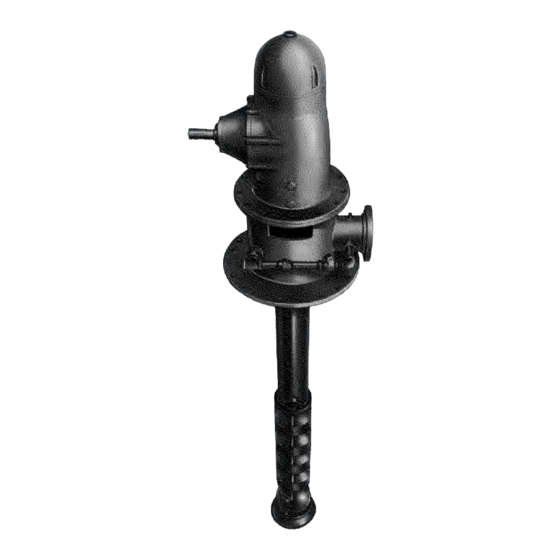
6 Installing the Bowl Assembly 6.1 Bowl assembly installation The following howl installation instructions apply to pumps shipped disassembled. Figure 2: Typical VMP autoprime pump WARNING: Do not work under a heavy, suspended objects unless there is a positive support under it, which will protect personnel should a hoist or sling fail. - Page 19 Remove the wire after installing the coupling. NOTICE: Shaft threads are left hand. Keyed shaft coupling: When a pump is equipped with keyed shafts assemble as follows: Install retainer (650) and insert key (730D) onto shaft. VMP Installation, Operation and Maintenance Instructions...
- Page 20 Do not drop any foreign object into the bowl assembly. Such an object can cause serious dam- age to the pump and any downstream components. Any foreign object dropped into the bowl assembly must be retrieved prior to continuing assembly. VMP Installation, Operation and Maintenance Instructions...
-
Page 21: Installing The Column
(660). Use care not to apply wrenches on bearing journal sur- faces. (See Figure 2: Typical VMP autoprime pump on page CAUTION: Use Molykote Dow-Corning or equal for all galling material such as 316 stainless steel. - Page 22 Tighten capscrews gradually and uniformly. NOTICE: Do not over-tighten flange bolts in order to make flange faces meet. Flange faces are designed to be separated by bearing retainer. VMP Installation, Operation and Maintenance Instructions...
-
Page 23: Installing The Discharge Head
Orient the discharge head in the required position and lower head, aligning the vertical hole with the headshaft protruding above the column until discharge head engages the bearing retainer (652) register. Install capscrews and secure discharge head to bearing retainer. Tighten capscrews gradu- ally in diametrically opposite pairs. VMP Installation, Operation and Maintenance Instructions... - Page 24 Hoist bowl, column, and head assembly, and remove elevator damp, or supports from barrel open- ing. Lower bowl, column and head assembly until discharge head flange engages barrel. Install cap- screws and secure discharge head to barrel. Tighten capscrews gradually in diametrically opposite pairs. VMP Installation, Operation and Maintenance Instructions...
-
Page 25: Stuffing Box Installation
Place split gland in the stuffing box. Thread nuts (735B) and tighten with a wrench and then relieve the nuts and take up only finger tight. Thread bypass line (624) into stuffing box. VMP Installation, Operation and Maintenance Instructions... - Page 26 Do not over-tighten stuffing box. It can wear out packing prematurely and seriously damage the shaft. If a lubrication line is being installed, connect tubing from reservoir to stuffing box. Refer to 10.2 Primacyclamatic tank operation on page 25 for primacyclamatic tank operation. VMP Installation, Operation and Maintenance Instructions...
-
Page 27: Mechanical Seal Installation
When reservoir is full, excess fluid returns to barrel through line "B". During reprime cycle (when pump pressure is lost) gravity flow back through line "A" keeps seal or stuffing box bushing constantly lubricated. Reservoir pressure is equalized to barrel pressure through line "B". VMP Installation, Operation and Maintenance Instructions... -
Page 28: Installing The Driver (Vhs)
Figure 9: Hollow shaft gearhead installation Orient the gearhead with the input shaft in the required position and align the mounting holes with the mating tapped holes in the discharge head. Continue to lower the gearhead until the registers VMP Installation, Operation and Maintenance Instructions... - Page 29 17.1 Recommended lubricants on page 55. Consult the manufacturer's instructions for frequency of oil change and other data on maintenance. CAUTION: Do not use automotive oils. VMP Installation, Operation and Maintenance Instructions...
-
Page 30: High Profile Discharge Head
Slide the driveshaft downward through hollow shaft of gearhead. Disassemble the coupling (if assembled) and slide driver hub (610) onto the driveshaft with key (730B) in place. Thread ring (607) onto the driveshaft and slide driver hub over ring. VMP Installation, Operation and Maintenance Instructions... -
Page 31: Impeller Adjustment
With impellers touching bowl faces, turn adjusting nut (604) counterclockwise until face of ad- justing nut makes contact with motor coupling. Align hole "A" in adjusting nut and hole "C" in motor coupling. VMP Installation, Operation and Maintenance Instructions... -
Page 32: Installation Of Hollow Shaft Electric Motor
Eccentricity at this point may be due to a bent shaft or to foreign particles be- tween butting ends of shaft sections. If there is eccentrically, the cause must be found and corrected before proceeding. Remove driver coupling. VMP Installation, Operation and Maintenance Instructions... -
Page 33: Separate Headshaft And Driveshaft
11.6 Separate headshaft and driveshaft on page 11.10 Impeller adjustment - open or enclosed Adjustment is accomplished by turning adjusting nut (601). (See Figure 10: Hollow shaft adjusting nut on page Same as steps 12.3 Impeller adjustment on page VMP Installation, Operation and Maintenance Instructions... -
Page 34: Installing The Driver (Vss)
The coupling between the driveshaft and pump- shaft may be a non-spacer, or a spacer type, . Install the right angle gear driver as follows: VMP Installation, Operation and Maintenance Instructions... - Page 35 On gearheads having non-reverse ratchet or pins, manually tum the gearhead shaft clockwise (viewed from above) until the non-reverse ratchet or pins fully engage. VMP Installation, Operation and Maintenance Instructions...
-
Page 36: Impeller Adjustment
13. Install spacer (612) and secure to driver hub (6!0) with capscrews (759B) and nuts (735C). 12.3 Impeller adjustment (See Figure 13: Flanged adjustable coupling on page 33 Figure 14: Flanged adjustable coupling with spacer on page 33.) Adjustment is accomplished by turning adjusting plate (613). Open impellers: VMP Installation, Operation and Maintenance Instructions... -
Page 37: Installation Of Solid Shaft Electric Motor
Install split ring (722) in the groove and slide driver hub down over the split ring to capture it. 12. Install spacer (612) and secure to driver hub (610) with capscrews (759B) and nuts (735C). VMP Installation, Operation and Maintenance Instructions... -
Page 38: Impeller Adjustment - Open Or Enclosed
Proceed as follows: Figure 15: Thrust pot installation Install housing on center plate of driver support (see Figure 16: Thrust pot bearing arrangement on page dotted lines) and secure with capscrews (760Q). VMP Installation, Operation and Maintenance Instructions... - Page 39 12.6 Thrust pot installation Remove capscrew (757Q). Figure 16: Thrust pot bearing arrangement VMP Installation, Operation and Maintenance Instructions...
- Page 40 14. Impeller adjustment- open or enclosed: When a thrust pot is provided, impeller adjustment is identi- cal to impeller adjustment in Installing the Driver (VHS), Steps 1 through 4, except that the adjusting nut (604B) is located on the thrust pot, instead of on top of the driver. VMP Installation, Operation and Maintenance Instructions...
-
Page 41: Pump Startup And Operation
Where leakage occurs immedi- ately and remains constant, unaffected by running, it usually indicates secondary seal (shaft packing) damage, or seal faces are warped out of flat. Refer to Troubleshooting for probable cause. VMP Installation, Operation and Maintenance Instructions... -
Page 42: Autoprime Functional Description
13.6 Autoprime functional description 13.6 Autoprime functional description When the model VMP Autoprime pump breaks suction in the priming stage or during stripping, the main discharge check valve closes against shore pressure, allowing the Autoprime valve to open and drain... -
Page 43: Maintenance
Change lubricant in gearhead. 2,000 or once a year Lubricate driveshaft. See manufacturer's instructions for correct lubricant. 200 continuous service or 500 nor- mal service. Tighten all loose bolts and check for excessive vibration. As required. VMP Installation, Operation and Maintenance Instructions... - Page 44 Table 3: Thrust pot lubrication Bearing arrangement 1800 1500 1200 1000 Quantity (oz.) Duplex 2000 Triplex (hrs) Duplex 2600 Triplex (hrs) Duplex 2900 Triplex (hrs) Duplex 2967 Triplex (hrs) Duplex 3467 Triplex (hrs) Duplex 3733 Triplex (hrs) VMP Installation, Operation and Maintenance Instructions...
-
Page 45: Troubleshooting
6. Pump takes too much power. Damaged impeller. Inspect, replace if damaged. Foreign object lodged be tween impeller Remove object as required. and bowl. Specific gravity higher than pump de- Test liquid for viscosity and specific signed for. gravity. VMP Installation, Operation and Maintenance Instructions... - Page 46 14. Seal leaks, nothing appears to Faces are not flat. Seal faces should be replaced or re-lap- be wrong. ped. Also see Trouble 11-A. VMP Installation, Operation and Maintenance Instructions...
- Page 47 C. Seal is running too hot. Check for possible rubbing of some seal component along the shaft. Recircula- tion or bypass line may be necessary. D. Improper choice of seal. Consult factory. VMP Installation, Operation and Maintenance Instructions...
-
Page 48: Pump Disassembly
16.2 Thrust pot disassembly Remove pump flexible half-coupling. Remove capscrew (757QJ). See Figure 16: Thrust pot bearing arrangement on page Unscrew adjusting nut (604B) and remove from shalt. VMP Installation, Operation and Maintenance Instructions... -
Page 49: Stuffing Box Disassembly
10. Remove capscrews that secure discharge head (600) to top column (64l ). Lift pump assembly and rotate clamps as necessary to remove all capscrews. Hoist discharge head of the top column. Re- move bearing retainer (652). VMP Installation, Operation and Maintenance Instructions... -
Page 50: Bowl Disassembly
17. Install two eyebolts diametrically opposite in bowl assembly. Attach a sling to eyebolts and to hoist hook. Hoist bowl assembly and place horizontally on blocks. 16.4 Bowl disassembly There are two types of bowl assemblies, turbine and mixed flow, and several different types of impeller construction. VMP Installation, Operation and Maintenance Instructions... - Page 51 Figure 18: Mixed flow impellers various constructions The bowl assembly shown in Figure 2: Typical VMP autoprime pump on page 16 is composed of the suction bell, diffuser case, adapter case, intermediate bowl, top bowl, mixed now impeller, with key, thrust and snap rings, turbine impeller with taper collets, bearings and a mixed now pumpshaft with coupling connecting to turbine pumpshaft.
-
Page 52: Turbine Bowls
Match mark bowl assembly in sequence of disassembly to aid in the reassembly procedure. 16.5 Turbine bowls Figure 2: Typical VMP autoprime pump on page Remove capscrews that secure top bowl (669) to intermediate bowl (670). Slide top bowl off the pumpshaft (660), impeller is now exposed. -
Page 53: Priming Stage - Mixed Flow
(674) is now exposed. 16.6 Priming stage - mixed flow Figure 2: Typical VMP autoprime pump on page 16 Remove capscrews that secure suction bell (689) to diffuser case (708) and remove suction bell. Remove threaded or keyed shalt coupling (649), as applicable. Refer to 16.3 Stuffing box disassem-... -
Page 54: Turbine Bowl - Wear Rings Removal
16.16 Bowl reassembly Figure 2: Typical VMP autoprime pump on page Press in new bearings (672), (709), (690) as required utilizing an arbor press or other suitable tool. -
Page 55: Stuffing Box Reassembly
Duplex bearings: Lightly grease first bearing (791B) and slide it on spindle (605) with heavy or wide side of inner race against shoulder of spindle. Use Chevron Grade 2 SRI grease or equal. (See Figure 16: Thrust pot bearing arrangement on page 37). VMP Installation, Operation and Maintenance Instructions... -
Page 56: Pump Reassembly
17.1 Recommended lubricants on page 55 list of recommended lubricants. Reinstall the pump as described in Installing the pump through Installing the Driver (VSS). Refer to Pump Startup and Operation for starting and adjusting procedures for the pump. VMP Installation, Operation and Maintenance Instructions... -
Page 57: Recommended Lubricants
Regal Oil A (R&O) Regal Oil A Regal Oil C Regal Oil F (R&O) No. 2 (R&O) (R&O) Fiske Bros. Refin- Lubriplate 130M (0° Lubriplate 3V Lubriplate 3V Lubriplate APG Lubriplate ing Co. to 120°F) APG 90 VMP Installation, Operation and Maintenance Instructions... -
Page 58: Parts List
When ordering spare and replacement parts the pump serial number, type and size of pump must be given. Refer to nameplate. This is essential in order that Goulds Pumps may identify the pump and fur- nish the correct replacement part. Give the name and item number of the part as listed in parts list with... - Page 59 Description Retainer Ring-Split 730D Sleeve 759E Capscrew Stuffing box assembly Figure 8: Stuffing box on page Table 7: Stuffing box parts list Part Number Description Box-Stuffing Bearing Gland-Split 620A Rings - Packing Line- Bypass VMP Installation, Operation and Maintenance Instructions...
- Page 60 Figure 13: Flanged adjustable coupling on page 33 Figure 14: Flanged adjustable coupling with spacer on page Table 10: Flanged adjustable coupling-solid shaft driver parts list Part Number Description Hub-Driver Spacer Plate-Adjusting Hub-Pump Ring - Split Driver VMP Installation, Operation and Maintenance Instructions...
- Page 61 Capscrew Mixed flow impellers various constructions Figure 18: Mixed flow impellers various constructions on page Table 13: Mixed flow impellers various constructions parts list Part Number Description Impeller- Mixed Flow Collet - Taper Washer VMP Installation, Operation and Maintenance Instructions...
- Page 62 18.3 Return parts Part Number Description Ring - Thrust 730F 759H Capscrew 760L Capscrew 774C Setscrew VMP Installation, Operation and Maintenance Instructions...
- Page 63 Visit our website for the latest version of this document and more information: www.gouldspumps.com ITT - Goulds Pumps Vertical Products Operation 3951 Capitol Avenue City of Industry, CA 90601-1734 Form IOM.VMP.en-US.2022-03 ©2022 ITT Corporation The original instruction is in English. All non-English instructions are translations of the original instruction.
Need help?
Do you have a question about the VMP and is the answer not in the manual?
Questions and answers