Table of Contents
Advertisement
Chapter 1 General Introduction....................................................................................................3
1.1 Summary.............................................................................................................................3
1.2 Product List.........................................................................................................................3
1.3 Environmental Condition................................................................................................... 3
1.4 specification........................................................................................................................ 5
1.4.1 display specification.....................................................................................................5
1.4.2 PLC specification......................................................................................................... 5
1.4.3 Appearance................................................................................................................9
1.4.4 Dimension................................................................................................................11
Chapter 2 PLC Introduction....................................................................................................... 11
2.1 Functions...........................................................................................................................11
2.1.1 CPU Status and LEDs................................................................................................ 11
2.1.2 USB Programming port..............................................................................................12
2.1.3 Serial Communication Port........................................................................................13
2.1.4 High Speed Counter and High Speed Pulse Output.................................................. 13
2.1.5 Edge Interrupts........................................................................................................... 14
2.1.6 Data Retentive and Data Backup............................................................................... 14
2.1.7 Real-time Clock (RTC).............................................................................................. 15
2.1.8 Backup Battery...........................................................................................................15
2.2 Wiring diagram................................................................................................................. 16
2.3 Dimension.........................................................................................................................19
2.4 Technical Specification.....................................................................................................20
Chapter 3 Software Introduction................................................................................................22
3.1 HMI programming............................................................................................................22
3.1.1 Create project............................................................................................................. 22
3.1.2 Edit configuration ...................................................................................................25
3.1.3 download link for HMI manual.............................................................................. 25
CONTENT
Kinco-HP
User Manual
1
Advertisement
Table of Contents

Related Manuals for Kinco HP043


Summary of Contents for Kinco HP043
-
Page 1: Table Of Contents
Kinco-HP User Manual CONTENT Chapter 1 General Introduction....................3 1.1 Summary..........................3 1.2 Product List.........................3 1.3 Environmental Condition....................3 1.4 specification........................5 1.4.1 display specification.....................5 1.4.2 PLC specification......................5 1.4.3 Appearance........................9 1.4.4 Dimension........................11 Chapter 2 PLC Introduction....................... 11 2.1 Functions...........................11 2.1.1 CPU Status and LEDs....................11 2.1.2 USB Programming port....................12... - Page 2 Kinco-HP User Manual 3.2 PLC........................... 25 3.2.1 introduction........................ 25 3.2.2 Install driver of USB programming port..............25 3.2.3 High speed counter.....................38 3.2.3.1 Operation Modes and Inputs of the High-speed Counters........38 3.2.3.2 Control Byte and Status Byte..................39 3.2.3.3 Preset value (PV value) setting................41 3.2.3.4 “CV=PV”...
-
Page 3: Chapter 1 General Introduction
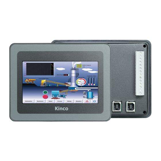
Chapter 1 General Introduction 1.1 Summary Kinco HMI-PLC combine HMI and PLC. It is Kinco ecomony integrated product. Based on powerful functions、high performance and high reliability, Kinco improve hardware designing of HMI-PLC. It cancel the wiring and communication of HMI and PLC, so it will reduce cost. - Page 4 Kinco-HP User Manual specifications. The following table lists the conditions and requirements for HMI-PLC to work properly. It is the user's responsibility to ensure that the service conditions are not exceeded. Transport and storage temperature -10℃~+60℃ Ambient relative 10%~95%, no condensation...
-
Page 5: Specification
Kinco-HP User Manual Ingress Protection Rating IP65 1.4 specification 1.4.1 display specification Type HP043 HP070 4.3” TFT(16:9) LCD size 7” TFT Resolution 480*272 800*480 Color 65536 Brightness 250cd/m2 300cd/m2 Back light 4 lines,resistor web(4H) Touch panel Life 50000 hours Memory... - Page 6 Kinco-HP User Manual Type J, Type K, Type E, Type S optional,Internal/external compensation Accuracy : 24 bits ADC ,0.1% F.S. Expansion Programming port USB2.0 2*RS485,max. 115.2kbps. 1*RS485,max. 115.2kbps. PORT1 support Programming port 、 Modbus RTU master and Programming port 、 Modbus Serial port slave、free protocol.
- Page 7 Kinco-HP User Manual Data backup E2PROM,448 bytes Retentive range 4K bytes. Lithium battery ,3 year at normal temperature Others 1ms time base:4 10ms time base:16 100ms time base:236 2,0.1ms time base. Interrupt Counter Yes. The difference is less than 5min/month at 25℃.
- Page 8 Kinco-HP User Manual frequency). Interrupt 4 ,I0.0-I0.3 can be on/off interrupt. Memory area Programming Max. 4K instruction M area 1K bytes;V area 4K bytes Users data E2PROM,448 bytes Data backup V area 1K bytes:VB0-VB1023 ;C area :C0-C63. Retentive range 3 year at normal temperature Others 1ms time base:4...
-
Page 9: Appearance
Kinco-HP User Manual 1.4.3 Appearance display and control area HP043 FRONT digital IO Digital IO HMI expansion memory Power supply Analog IO PLC programming port PLC RS485 HMI programming HP043 BACK... - Page 10 Kinco-HP User Manual display and control area Indicator HP070 FRONT Digital Digital IO HMI expansion memory Analog IO Analog IO Power supply 24V PLC RS485 HMI&PLC PLC EX. HP070 BACK...
-
Page 11: Dimension
Kinco-HP User Manual 1.4.4 Dimension HP043 HP070 Dimension 132*102*40.1mm 204*150*38.55mm Cutout size 119*93mm 192*138mm Chapter 2 PLC Introduction 2.1 Functions 2.1.1 CPU Status and LEDs The CPU has two modes: STOP mode and RUN mode. In RUN mode, the CPU executes the main scan cycle and all interrupt tasks.In STOP mode, the CPU only process communication requests which comes from KincoBuilder software and other Modbus RTU master device.At the same time, all output points are immediately output... -
Page 12: Usb Programming Port
HMI-PLC uses USB (USB2.0 ) port as programming port. The connector port is same as HMI programming port. Users can use cables with same connector port for PLC programming.The USB Programming port of HP043 PLC and HMI are separately.While USB programming port of HP070 PLC and HMI are sharing one. -
Page 13: Serial Communication Port
2.1.4 High Speed Counter and High Speed Pulse Output HP043 provides 4 high speed counters (HSC0~HSC3). ( Note: HSC2 of HP043-20DTC could only support mode0 when input are I0.4). HP070 provides 2 high-speed counters, which are... -
Page 14: Edge Interrupts
User Manual Q0.0 Q0.1 Q0.4 HP043 HP070 2.1.5 Edge Interrupts I0.0-I0.3 in CPU support edge interrupt function, it can execute interrupt by rising edge and falling edge of input signal. By using this function, it can capture the rising edge and falling edge of input signal quickly. -
Page 15: Real-Time Clock (Rtc)
HMI-PLC can use certain specification lithium battery as backup battery. The backup battery of HP043 only supplies power to the PLC.When PLC is power-off, it will use the backup battery to maintain real-time clock and RAM. The HP070 backup battery supplies power to the RTC of the HMI and PLC to maintain the clock.. -
Page 16: Wiring Diagram
Kinco-HP User Manual when the battery is empty. The lithium battery is CR2032(3V) with connector. As shown in figure, user can order the battery separately. 2.2 Wiring diagram HP043-20DT... - Page 17 Kinco-HP User Manual HP043-20DTC...
- Page 18 Kinco-HP User Manual HP070-33DT...
-
Page 19: Dimension
Kinco-HP User Manual 2.3 Dimension HP043 HP070... -
Page 20: Technical Specification
Kinco-HP User Manual 2.4 Technical Specification DI Specifications Input type Source/Sink Rated input voltage DC 24V (Max. 30V) Rated input current 3.5mA@24VDC Max input voltage of logic 0 5V@0.7mA Common channel:11V@2.0mA Minimum input voltage of logic 1 Common channel: 15μs;... - Page 21 Kinco-HP User Manual · Mode 500VAC/1 min · Voltage HP043 AI Specification Signal 0-10V Resolution 12 bits Accuracy 0.3% F.S. Speed(each channel) 200 times /s Resistance Voltage mode:>4MΩ Common mode voltage (Signal voltage +Common mode voltage)≤15V. Signal K、 E 、...
-
Page 22: Chapter 3 Software Introduction
Kinco-HP User Manual Chapter 3 Software Introduction 3.1 HMI programming HMI programming software: Kinco HPBuilder. Download link for HMI software http://en.kinco.cn 3.1.1 Create project Process to create project based on Kinco HPBuilder. 1, create project Open Kinco HPBuilder 1.1 create new project click menu【File】--【new】... - Page 23 System will show ”Display Mode”, we can choose “Horizontal” or “Vertical” Click 【OK】 ③choose device—choose PLC type(communication protocol) Drag “Kinco PLC series” in 【Graph element window】to construct window 1.3 connect devices Drag “COM” of HMI to close left side of connector, until connector and “COM” move...
- Page 24 Kinco-HP User Manual 1.4 parameters setup-HMI Double click HMI, it will appearance 【HMI Atrribute】 (1) Find 【Task Bar】 (2) Cancel the “√” of “Display Task Bar” (3) Setup COM0 parameter at 【COM0 setting】based on PLC real communication (4) parameters. All others will be default...
-
Page 25: Edit Configuration
3.1.3 download link for HMI manual https://en.kinco.cn/Download/D_enUserManual/HMI/Kinco%20DTools%20User%20Manual. 3.2 PLC 3.2.1 introduction Kinco HMI-PLC use Kincobuilder programming software and same instructions, same as K5. HMI-PLC improve some functions, pls reference the manual. Pls reference Kincobuilder software 【Help】or download K5/K2 software for most functions. https://en.kinco.cn/Download/D_enUserManual/PLC/Software%20manualfor%20K5_2019051 6.zip... - Page 26 Kinco-HP User Manual figure: When connecting programming cable to HMI-PLC and PC first time, Windows system will detect new hardware and mention installing driver, users can install the driver according to the version of Windows. Fail in installing driver in Windows 7? ...
- Page 27 Kinco-HP User Manual...
- Page 28 Kinco-HP User Manual 2、If you have not internet, pls reference below information.
- Page 29 Kinco-HP User Manual Below picture is advanced starting of Win8 Find advanced starting, then choose 7 to forbid driver signature. (1) Install PLC drive according Window guidance. Choose driver files in Win8.
- Page 30 Kinco-HP User Manual...
- Page 31 Kinco-HP User Manual It will show “settings” when mouse at the right side of Window, then click “settings” (2)...
- Page 32 Kinco-HP User Manual Click “update and recovery” in the “PC settings” (3)...
- Page 33 Kinco-HP User Manual (4)Click “restart now” at advanced startup (5)Click advanced options...
- Page 34 Kinco-HP User Manual (6)click startup settings...
- Page 35 Kinco-HP User Manual (7) Click restart (8) This is the picture after computer restarting. Choose 7 to forbid driver signature inforcement, then PC restart.
- Page 36 Kinco-HP User Manual (9)Re-install PLC driver based on Window guidance. Choose driver files in the Win8 It will show below information, choose “ install this driver software anyway” (10) Figure as below after successful...
- Page 37 Kinco-HP User Manual...
-
Page 38: High Speed Counter
Kinco-HP User Manual 3.2.3 High speed counter HP043 provides 4 high speed counters HSC0-HSC3.while HP070 provides 2 high-speed counters, are HSC0, HSC1.High speed counter supports multiple modes: single phase, CW/CCW,AB phase (1 multiplication and 4 multiplication).Note: HP043-20DTC's HSC2 only supports mode 0, and the input is I0.4. -
Page 39: Control Byte And Status Byte
I0.4 I0.5 Single-phase up/down counter Clock with internal direction control:SM57.3 A/B phase quadrature counter Clock A Clock B Note: HP043-20DTC's HSC2 only supports mode 0, and the input is I0.4. HSC 3 Mode Description I0.6 I0.7 Single-phase up/down counter Clock with internal direction control:SM127.3... - Page 40 Kinco-HP User Manual SM37.6 SM47.6 SM57.6 SM127.6 Write new current value in HSC? 0= NO; 1= Yes SM37.7 SM47.7 SM57.7 SM127.7 Allow this high-speed counter? 0=NO; 1= YES HSC0 HSC1 HSC2 HSC3 Description SMD38 SMD48 SMD58 SMD128 Current value SMD42...
-
Page 41: Preset Value (Pv Value) Setting
Kinco-HP User Manual HSC0 HSC1 HSC2 HSC3 Description SM36.0 SM46.0 SM56.0 SM126.0 Reserved SM36.1 SM46.1 SM56.1 SM126.1 Reserved SM36.2 SM46.2 SM56.2 SM126.2 Reserved Fault multiple value SM36.3 SM46.3 SM56.3 SM126.3 table:0=No,1=Yes SM36.4 SM46.4 SM56.4 SM126.4 Reserved Current counting direction: SM36.5 SM46.5... - Page 42 Kinco-HP User Manual using multiple PV,then all PV value will get from PV table.The starting address of PV table is odd address of V area,such as 301(Means VB301). The format of PV table is as follows. Data Description Offset (...
-
Page 43: Cv=Pv" Envent No
Kinco-HP User Manual interrupt.For example,if it sets 3 PV values,such as 10,1000 and 1000,and the current counting value is 100 before HSC starts,then when the counting value reaches 110,1110 and 2110,it will execute corresponding“CV=PV” interrupt. “CV=PV”interrupt cyclic execution “CV=PV”interrupt cyclic execution is only valid when PV is set as relative value. -
Page 44: How To Use High Speed Counter
Kinco-HP User Manual “CV=PV”interrupt of 2nd PV … …(Plus 1) “CV=PV”interrupt of 32nd PV “CV=PV”interrupt of 1st PV “CV=PV”interrupt of 2nd PV HSC2 … …(Plus 1) “CV=PV”interrupt of 32nd PV “CV=PV”interrupt of 1st PV “CV=PV”interrupt of 2nd PV HSC3 …... - Page 45 Kinco-HP User Manual How to use HSC wizard: 1) Select the counter in【HSC】. 2) Check【Enable HSC】, and then continue following configuration. 3) Select counter mode in【Mode】. 4) Select the starting mode in【Start method】. There are two starting method: “Using HSC instruction”: If selecting this method, then it needs to execute HSC instruction...
-
Page 46: How To Use High Speed Pulse Output
7) For other options, please refer to the descriptions to HSC. 3.2.4 How to use high speed pulse output Kinco HMI-PLC HP043 provides 3 channels for high speed pulse output, they are Q0.0,Q0.1 and Q0.4. Q0.0 and Q0.1 support maximum 50KHz, and Q0.4 supports maximum 10KHz.HP070 provides 2 high-speed outputs, the channels are Q0.0, Q0.1. -
Page 47: High Speed Pulse Output Instruction
Kinco-HP User Manual 3.2.4.1 High speed pulse output instruction HMI-PLC provides 3types of instructions for high speed pulse output. 1) PLS: it is used to output PTO(Single segment or multiple segments) and PWM. 2) Position control: There are 5 instructions, include PREL(Relative positioning), PABS(Absolute positioning) ,PHOME(Homing), PJOG(Jogging) and PSTOP(Emergency stop). -
Page 48: High-Speed Pulse Output Function Of Hmi-Plc
If CR is 1,then PLS is executed. It won’t influence the value of CR. 3.2.4.2.1 High-speed Pulse Output Function of HMI-PLC HMI-PLC HP043 provides 3 PTO/PWM pulse generators that can be used to output PTO/PWM. HP070 supports 2 high-speed pulse outputs, correspondingly provides 2 PTO/PWM pulse generators for generating PTO/PWM output. - Page 49 The unit of cycle time is microsecond(us) or millisecond(ms).The maximum value of cycle time is 65535.The range of pulse number is 2~4,294,967,295.If the specified pulse number is less than 2, then KInco-K2 will set related error bit and prohibit the output.
-
Page 50: Pto/Pwm Register
Kinco-HP User Manual Initial cycle time (2 to 65535 times of the time 16-bit base) Reserved 16-bit 32-bit Pulse number(1 to 4,294,967,295) Initial cycle time (2 to 65535 times of the time 16-bit base) Reserved 16-bit Pulse number(1 to 4,294,967,295) 32-bit …... -
Page 51: Pto Operations
Kinco-HP User Manual All the default value for control byte, cycle time and pulse number are 0.The way to modify configuration of PTO/PWM is that configure related control registers first, if it is PTO multiple segment pulse, it also needs to configure profile table, and then execute PLS instruction. - Page 52 Kinco-HP User Manual Enable the PTO/PWM function Select PTO operation Select 1μs as the time base Allow updating the pulse number and cycling time. Set SMW68 according to desired cycle time. Set SMD72 according to desired pulse number.
-
Page 53: Pwm Operations
Kinco-HP User Manual Allow updating the pulse number Set SMD72 according to desired pulse number. Execute the PLS instruction to configure PTO0 and start it, then a new PTO with the updated pulse number shall be generated. Execute the PTO (Multiple-Segment Operation) Set control byte SMB67 according to the desired operation. -
Page 54: How To Use Position Control Instructions
Control Registers and Status Registers For the Position Control instructions,Kinco-K2 specifies a control byte for each high-speed output channel to store its configurations. Besides, it assigns a current value register(DINT) to store the pulse number which has outputted currently (This value will increase when run... - Page 55 Kinco-HP User Manual forward and decrease when run reverse).The following table describes the control byte and the current value. Description Q0.0 Q0.1 Q0.4 Read only. Current value (Increase when run forward, SMD212 SMD242 SMD262 decrease when run reverse).It indicates the pulse number which has already outputted.
- Page 56 Kinco-HP User Manual time for the reset bit to activate. When it needs to use this bit, try to avoid to keep this bit always 1 and also and also avoid to set this bit while the Position Control instruction (Include PHOME, PREL, PABS, JOG and PFLO_F) is executing, otherwise the counting value may be wrong.
-
Page 57: Can It Change Maximum Output Frequency When Position Control Instruction Is
The HP043 series has two analog input channels , HP043-20DTcan measure the voltage (0-10V),HP043-20DTC The measurement input signal can be J - type, K type, E type, S type,internal/exten optional.The HP070 has 3 analog channels, 2*AI (IV), 1*AO (IV). The signal form of the channel is configured in the programming software. -
Page 58: Wiring Diagram
Kinco-HP User Manual 3.3.1 Wiring diagram Please refer to 2.2 Wiring diagram 3.3.2 Measurement Ranges and The measured value Representation The input signal in each channel will sample ADC and counter. The results will be send to CPU AI area from expansion CAN. Then user programming can visit it. -
Page 59: Configuration In Software
Kinco-HP User Manual The following table are the range of signal.Among them,I stand for Actual Current,V stand for Actual Voltage. Signal Output range User assigned value in program 4-20mA 3.92-20.4mA I×1000 0-20mA 0-20.4mA 1-5V 0.96-5.1V V×1000 0-10V 0-10.2V 3.3.3 Configuration in software Hardware configuration in the software can be used to configure analog channel parameters. - Page 60 Kinco-HP User Manual channels,So the addresses of its two channels in turn are %AIW0、%AIW2. Channel Settings Signal form : Select the type of input signal for each channel. The sample values are automatically converted linearly within the CPU, The data conversion format please refer to 3.3.2 Measurement Ranges and The measured value Representation...
Need help?
Do you have a question about the HP043 and is the answer not in the manual?
Questions and answers