Table of Contents
Advertisement
Quick Links
Download this manual
See also:
User Manual
CHAPTER 1 GENERAL INTRODUCTION.............................................................................. 3
............................................................................................................................3
CHAPTER 2 CPU MODULE INTRODUCTION....................................................................... 5
........................................................................................................................... 5
2.1.1 Structure....................................................................................................................... 5
2.1.2 CPU Types.................................................................................................................... 5
.......................................................................................................................... 7
2.2.1 CPU Status and LEDs...................................................................................................7
2.2.2 Programming port and serial port................................................................................. 8
2.2.3 CAN port...................................................................................................................... 9
2.2.4 Expansion modules.......................................................................................................9
2.2.5 High Speed Counter and High Speed Pulse Output......................................................9
2.2.6 Edge Interrupts............................................................................................................. 9
2.2.7 Data Retentive and Data Backup................................................................................ 10
2.2.8 Real-time Clock (RTC)...............................................................................................10
2.2.9 Backup Battery........................................................................................................... 11
2.3 W
IRING DIAGRAM
........................................................................................................................ 15
2.5 T
ECHNICAL
CHAPTER 3 SOFTWARE INTRODUCTION..........................................................................16
......................................................................................................................... 16
CONTENT
CONTENT
CONTENT
CONTENT
..................................................................................................................... 3
............................................................................................. 4
..............................................................................................................12
................................................................................................15
K K K K inco
inco
inco
-K
-KS S S S series
-K
series
series
inco-K
series
1
Advertisement
Table of Contents

Related Manuals for Kinco KS Series


Summary of Contents for Kinco KS Series
-
Page 1: Table Of Contents
K K K K inco inco inco -KS S S S series series series inco-K series CONTENT CONTENT CONTENT CONTENT CHAPTER 1 GENERAL INTRODUCTION................3 1.1 S ..........................3 UMMARY 1.2 P ........................3 RODUCT 1.3 E ..................... 4 NVIRONMENTAL ONDITION CHAPTER 2 CPU MODULE INTRODUCTION............... - Page 2 K K K K inco inco inco -KS S S S series series series inco-K series 2.2 H ....................... 17 IGH SPEED COUNTER 2.2.1 Operation Modes and Inputs of the High-speed Counters..........17 2.2.2 Control Byte and Status Byte..................18 2.2.3 Preset value (PV value) setting...................20 2.2.4 “CV=PV”...
-
Page 3: Chapter 1 General Introduction
1.1 Summary Summary Kinco-K5 series PLC is a small and integrated PLC .It is Kinco new thin and high performance PLC. Based on high performance, high reliability and powerful functions of K5/K2, KS series use higher level CPU. KS has CANopen port, higher speed input and output, small size for installation. - Page 4 K K K K inco inco inco -KS S S S series series series inco-K series Altitude Up to 3000 m Mechanical Free falls With manufacturer's original packaging, 5 falls from 1m of height. conditions Normal Operation air temperature Open equipment : -10 --- +55°C; Enclosed equipment: -10 --- +40°C relative 10%~95%, no condensation Ambient...
-
Page 5: Chapter 2 Cpu Module Introduction
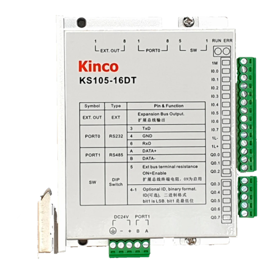
2.1.2 CPU CPU Types Types Types Types Kinco-KS provides different CPU models with a diversity of features and capabilities, all the CPU use DC24V power supply. The following table describes main technical data of each CPU model. Parameters KS105-16DT KS105C1-16DT... - Page 6 K K K K inco inco inco inco-K -KS S S S series series series series Analog Expansion CANopen master or CAN free potocol PORT0,RS232,support programming protocol, MODBUS RTU slave, free protocol Serial port PORT1,RS485,support programming protocol, MODBUS RTU master, free protocol High speed 4, Max 200KHz,support single and double...
-
Page 7: Functions
Kinco-KS provides two ways for manually changing the CPU status: Set all switch of CAN port [OFF],then PLC will be in STOP status.if any switch is [ON],PLC will be in RUN status. (use all 5 switches for KS105,use 1~4 switches for KS105C1,use 1~3 switches for KS105C2. - Page 8 K K K K inco inco inco -KS S S S series series series inco-K series KS separates errors into three levels: Fatal error, Serious error, Normal error. When CPU detects an error, it will use different way to handle according to error level and turn on Err LED, then it will save the error code in sequence for user analysis.
-
Page 9: Can Port
2.2.4 Expansion Expansion modules modules KS105-16DT has expansion port, it can connect KS series expansion modules CAN1 port of KS105C2-16DT can work as expansion port, also it support protocol. Users can use them directly without setup, PLC can identify it automatically. -
Page 10: Backup Battery
K K K K inco inco inco -KS S S S series series series inco-K series Data backup is that CPU provides an E PROM to store data permanently. At power on, the CPU will restore the data from E PROM into RAM to execute. -
Page 11: W Iring Diagram
K K K K inco inco inco -KS S S S series series series inco-K series Wiring Wiring diagram diagram 2.3 Wiring Wiring diagram diagram... - Page 12 K K K K inco inco inco -KS S S S series series series inco-K series...
- Page 13 K K K K inco inco inco -KS S S S series series series inco-K series...
-
Page 14: Dimension
K K K K inco inco inco -KS S S S series series series inco-K series Dimension Dimension 2.4 Dimension Dimension Technical Technical Specification Specification 2.5 Technical Technical Specification Specification � DI Specifications Input type Source/Sink Rated input voltage DC 24V (Max. 30V) Rated input current 3.5mA@24VDC Max input voltage of logic 0... -
Page 15: Chapter 3 Software Introduction
K K K K inco inco inco -KS S S S series series series inco-K series · Mode Opto-electrical isolation · Voltage 500VAC/1 min � DO Specifications(Transistor type) Output type Source DC24V,allowance range: DC20.4V—DC28.8V.(Same Rated power supply voltage as power supply) Output current per channel Rated current:200mA,max.300mA @24VDC Instant impulse current per channel... -
Page 16: H Igh Speed Counter
K K K K inco inco inco -KS S S S series series series inco-K series High High speed speed counter counter 2.2 High High speed speed counter counter KS provides 4 high speed counters HSC0-HSC3.All can support up to 200KHz High speed counter supports multiple modes: single phase, CW/CCW,AB phase (1 multiplication and 4 multiplication). - Page 17 K K K K inco inco inco -KS S S S series series series inco-K series A/B phase quadrature counter Clock A Clock B Reset HSC 2 2 2 2 Mode Mode Description Description I0.4 I0.4 I0.5 I0.5 Mode Mode Description Description I0.4...
- Page 18 K K K K inco inco inco -KS S S S series series series inco-K series HSC0 HSC0 HSC1 HSC1 HSC2 HSC2 HSC3 HSC3 Description Description HSC0 HSC0 HSC1 HSC1 HSC2 HSC2 HSC3 HSC3 Description Description SM141.0 SM151.0 SM161.0 SM171.0 Use multiple preset value:0=No.
- Page 19 K K K K inco inco inco -KS S S S series series series inco-K series SM36.4 SM46.4 SM56.4 SM126.4 Reserved Current counting direction: SM36.5 SM46.5 SM56.5 SM126.5 0 = Down; 1= Up Current value equal to preset value: SM36.6 SM46.6 SM56.6 SM126.6...
- Page 20 K K K K inco inco inco -KS S S S series series series inco-K series ( ) OFFSET OFFSET OFFSET OFFSET Data Data Data Data type type type type Description Description Description Description BYTE Quantity of PV DINT First PV DINT Second PV …...
- Page 21 K K K K inco inco inco -KS S S S series series series inco-K series counting value reaches 110,1110 and 2110,it will execute corresponding“CV=PV” interrupt. � � � � “ “ “ “ CV=PV CV=PV CV=PV CV=PV” ” ” ” interrupt interrupt interrupt cyclic...
- Page 22 K K K K inco inco inco -KS S S S series series series inco-K series “CV=PV”interrupt of 2nd PV … …(Plus 1) “CV=PV”interrupt of 32nd PV “CV=PV”interrupt of 1st PV “CV=PV”interrupt of 2nd PV HSC3 … …(Plus 1) “CV=PV”interrupt of 32nd PV 2.2.5 2.2.5 How to to to to use...
- Page 23 K K K K inco inco inco -KS S S S series series series inco-K series How to use HSC wizard: 1 ) Select the counter in 【 HSC 】 . 2) Check【Enable HSC】, and then continue following configuration. 3) Select counter mode in【Mode】. 4)...
- Page 24 Kinco-KS provides 4 channels for high speed pulse output, they are Q0.0,Q0.1 and Q0.4,Q0.5.All support PT0 and PWM output. . Q0.0 and Q0.1,0.4 support maximum 200KHz, and Q0.5supports maximum 10KHz. KS have one direction output channel for every high speed output. KS provide 1 direction enable control in SM area.
- Page 25 K K K K inco inco inco -KS S S S series series series inco-K series positioning) ,PHOME(Homing), PJOG(Jogging) and PSTOP(Emergency stop). User can use these instructions to achieve positioning control easily .Note: Note: Note: When When using using position position control control...
- Page 26 Function Function The Kinco-KS provides 4 PTO/PWM pulse generators that can be used to output PTO/PWM. Thereof, one generator is assigned to Q0.0, called PWM0 or PTO0; the second one is assigned to Q0.1, called PWM1 or PTO1,and the third one is assigned to Q0.4,called PWM2 or PTO2. The forth one is assigned to Q0.5,called PWM3 or PTO3.
- Page 27 65535.The range of pulse number is 2~4,294,967,295.If the specified pulse number is less than 2, then KInco-KS will set related error bit and prohibit the output. PTO function provides single segment of pulse and multiple segment of pulse.
- Page 28 K K K K inco inco inco inco-K -KS S S S series series series series … … … 1 1 1 1 All the offsets in this column are relative to the starting position of the profile table. Notice: the starting position of the profile table must be an odd address in V area, e.g. VB3001. 2.3.2.2 2.3.2.2 2.3.2.2...
- Page 29 K K K K inco inco inco -KS S S S series series series inco-K series configure profile table, and then execute PLS instruction. Each PTO/PWM generator also provides a status bytes in SM area, user can get the status information of PTO/PWM generator from the status bytes, as shown in following table.
- Page 30 K K K K inco inco inco -KS S S S series series series inco-K series • Select PTO operation • Select 1μs as the time base • Allow updating the pulse number and cycling time. Set SMW68 according to desired cycle time. Set SMD72 according to desired pulse number.
- Page 31 K K K K inco inco inco -KS S S S series series series inco-K series • Select 1μs as the time base • Allow updating the pulse number Set SMD72 according to desired pulse number. Execute the PLS instruction to configure PTO0 and start it, then a new PTO with the updated pulse number shall be generated.
- Page 32 K K K K inco inco inco -KS S S S series series series inco-K series � � � � Execute Execute Execute Execute PWM Set control byte SMB67 according to the desired operation. For example, SMB67 = B#16#D3 indicates: •...
- Page 33 K K K K inco inco inco inco-K -KS S S S series series series series its configurations. Besides, it assigns a current value register(DINT) to store the pulse number which has outputted currently (This value will increase when run forward and decrease when run reverse).The following table describes the control byte and the current value.
- Page 34 K K K K inco inco inco -KS S S S series series series inco-K series only, if user needs to modify the current value, it can use following methods. • • • • Method Method Method Method 1 1 1 1 User reset bit to clear current value.
- Page 35 K K K K inco inco inco -KS S S S series series series inco-K series wrong. Following takes channel 0 as example to describe how to modify current value: (* Network 0 *) (*Based on homing signal, hen it moves to homing, t requires to set current value as 100.*) %SM0.0 PHOME 0, %M0.0, %M0.1, %M0.2, %VW0, %VW2, %VW4, %VD6, %VW10, %M0.4, %M0.5, %MB1 (* Network 1 *)
- Page 36 K K K K inco inco inco -KS S S S series series series inco-K series How to to to to use CANopen CANopen 2.4 How use CANopen CANopen KS105C1-16DT has 1 CAN port, CAN2 KS105C2-16DT has 2 CAN ports,CAN1 and CAN2. CAN2 support CANopen master protocol and free protocol.CAN1 support free protocol.
Need help?
Do you have a question about the KS Series and is the answer not in the manual?
Questions and answers