Table of Contents
Advertisement
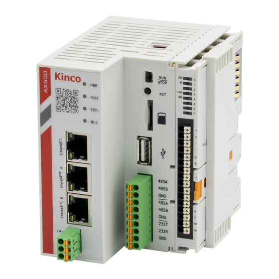
AX500 Intelligent Controller
Intelligent Controller User Guide
AX500 Intelligent Controller
AX500 intelligent controller is a medium-sized PLC developed based on CODESYS. It fully supports
IEC61131-3 programming system and multiple site real-time bus. It supports cam, CNC, and other
synchronous movement control providing various interfaces to meet the needs of projects.
This manual describes the specifications, characteristics and using methods of the AX500
controller. For the user program, hardware information and other information of this product,
please refer to the other manual.
Safety Instructions
Safety Precautions
1. Before installing, operating, and maintaining the product, please read and observe these safety
precautions.
2. To ensure personal and equipment safety, please follow all marks on the product and safety
Advertisement
Table of Contents

Related Manuals for Kinco AX500


Summary of Contents for Kinco AX500
- Page 1 Intelligent Controller User Guide AX500 Intelligent Controller AX500 intelligent controller is a medium-sized PLC developed based on CODESYS. It fully supports IEC61131-3 programming system and multiple site real-time bus. It supports cam, CNC, and other synchronous movement control providing various interfaces to meet the needs of projects.
- Page 2 precautions of the manual when installing, operating, and maintaining the product. 3. The "CAUTION", "WARNING" and "DANGER" items in the manual do not represent all the safety matters to be observed but are supplementary to all safety precautions. 4. This product should be used in an environment stated in the design specifications. Otherwise, it may cause malfunctions.
- Page 3 lightning shock can't be applied to the PLC's power supply input terminals, signal input terminals and output terminals and so forth, so as to avoid damage to the equipment. Wiring WARNING ◆ Wiring must be carried out by personnel who have the necessary electrical training and experience. ◆...
-
Page 4: Maintenance And Inspection
Maintenance & Inspection WARNING ◆ Maintenance & inspection must be carried out by personnel who have the necessary electrical training and experience. ◆ Do not touch the terminals while the power is on. Failure to comply may result in electric shock or malfunction. -
Page 5: Product Nameplate
Product Nameplate General Specifications Item AX500 Power Supply DC 24V (-25% ~ +20%) CPU Specifications Quad-core 1.5GHz Memory Hard Drive Capacity Program Capacity 32MB User Data Capacity 128MB Non-volatile Storage Capacity 1* USB 2.0 Network 1* Gigabit Ethernet Port; 2* Fast Ethernet Ports Serial Port 2* RS485;... - Page 6 Components Information ④ ① ⑤ ⑥ ⑦ ② ⑧ ③ Name Description Status Indicator Status Indicator The indicators on the display panel from top to bottom are PWR/RUN/ERR/BUS, specific definitions are as follows: Name Sign Status Description Power Indicator Green ON: Power On ON: User Program ①...
- Page 7 Port Function Description 1. User program download and debugging EtherNet Ethernet 2. Modbus TCP 3. Socket (TCP, UDP) 1. EtherCAT Master EtherCAT A EtherCAT 2. Support Auto-Scan 3. Support Independent Configuration of Axis/IO 1. EtherCAT Master 2. Support Auto-Scan 3. Support Independent Configuration of Axis/IO EtherCAT B EtherCAT/ Ethernet 4.
- Page 8 The definition of the communication terminal pins is as follows: Name Function 485A RS485+(COM1) 485B RS485-(COM1) ⑧ 485 Communication Ground 485A RS485+(COM2) 485B RS485-(COM2) RS485 Communication Ground 232T R232 Reception (COM3) 232R R232 Transmission (COM3) RS232 Communication Ground...
- Page 9 Power Terminal Arrangement ① ② Name Description The pin diagram and definition for the coupler indicator lights are as follows: ① Name Function Description IO Coupler and IO Module Uses Power Indicator Power Supply IO Coupler and IO Module Local Power Indicator Power Supply Communication...
- Page 10 Input Indicator ON: Input Valid Input Indicator ON: Input Valid Input Indicator ON: Input Valid Input Indicator ON: Input Valid Input Indicator ON: Input Valid Input Indicator ON: Input Valid Input Indicator ON: Input Valid Input Indicator ON: Input Valid The electrical pin diagram and pin definitions for the coupler are as follows: ②...
-
Page 11: Function Description
Common Terminal DI Terminal Instructions External F_24 and F_0V power supply are required when using the expansion module and the expansion modules. DI supports bipolar wiring. ① NPN wiring as shown in the figure below: ② PNP wiring as shown in the figure below: Function Description 1. - Page 12 The possible states of the RUN indicator are as follows: (1) On when the user program is running; Off when the user program is stopped; (2) Flashes rapidly during program downloading; Returns to a steady state after the download is completed;...
- Page 13 Save boot application file Copy the user program (Application. app and Application. crc) to the root directory of the USB flash disk, then insert the USB flash disk to the USB port of the controller, restart the controller. (2) Download source code to hard drive of the program - 32MB Max...
-
Page 14: Firmware Upgrade
3. Firmware Upgrade Place the upgrade format firmware package in the root directory, then restart the controller. After a successful upgrade, an “upgradeOK” file will be generated. (1) Place the firmware package in the root directory, then insert the USB drive into the controller's USB port. - Page 15 A upgradeOK file appears after the upgrate successed (3) Upgrade the firmware through the software. Place the firmware package under the root directory of the controller. Restart the controller, and a upgradeOK file will appear after the upgrade success. Enter the IP address to connect to the controller. After successful connection, upload the firmware package and restart the controller A upgradeOK file appears after the upgrate successed...
- Page 16 Multi-node Connection When there are many nodes on the RS485 bus, it is imperative to use a daisy-chain topology. If branch topology is required for connections, the branch length from the bus to each node should be as short as possible, ideally not exceeding 3 meters.
- Page 17 RS485 Bus Wiring When configuring the RS485 communication interface for the AX500 series programmable controller, ensure the following: Three Cables: Make sure the on-site RS485 bus includes three cables, namely 485A, 485B, and GND. Correct Wiring: Check whether the wiring terminals are connected incorrectly or reversed. Ensure that 485A and 485B are not reversed, and GND is correctly grounded.
-
Page 18: Ethernet Connection
4. Ethernet Connection The AX500 series controller provides 3 network ports, which are described as follows: Nework Port Function Support programming protocols, connect to HMI, and communicate via EtherNET Modbus/TCP. EtherCAT A EtherCAT master port A EtherCAT B EtherCAT master port B (Ethernet functionality optional) With the Ethernet port, the controller can be connected point-to-point with devices such as a computer, HMI, etc. -
Page 19: Mechanical Design
It is recommended that the computer's CPU clock speed is above 2GHz, as lower speeds may affect the software's operating speed. The PC and AX500 controller are connected via a LAN network cable. It is recommended to connect the AX500 through a router to the LAN network. This method allows for longer communication... -
Page 20: Mounting Guide
◆ Do not overtighten the device to avoid damaging terminals and other components. Add Device Packages to CODESYS It is required to install the device package of the AX500 to the CODESYS package manager at the first operation of AX500. AX500 device package can be downloaded at Kinco official website or Kinco technical support. - Page 21 Install the device package Open the AX500 device package Allow unsigned and self-signed packages...
-
Page 22: Warranty Agreement
Installation complete Choose AX500 as the device when creating a new project Warranty Agreement This product comes with an eighteen-month warranty period (based on the information on the body's barcode. If there are special agreements, the terms of the purchase contract apply). During the warranty period, if the product malfunctions or is damaged under normal usage as specified in the user manual, our company will provide free repair services. -
Page 23: Product Warranty Card
If you encounter any issues during the service process, please contact our agents or our company promptly. Purchasing this product implies acceptance of this warranty agreement. Kinco reserves the right to interpret this agreement. Product Warranty Card...
Need help?
Do you have a question about the AX500 and is the answer not in the manual?
Questions and answers